Transcription
BURIED FIBER OPTIC INTRUSION SENSORA ThesisbyERIC WILLIAM MAIERSubmitted to the Office of Graduate Studies ofTexas A&M Universityin partial fulfillment of the requirements for the degree ofMASTER OF SCIENCEMay 2004Major Subject: Electrical Engineering
BURIED FIBER OPTIC INTRUSION SENSORA ThesisbyERIC WILLIAM MAIERSubmitted to Texas A&M Universityin partial fulfillment of the requirementsfor the degree ofMASTER OF SCIENCEApproved as to style and content by:Henry F. Taylor(Chair of Committee)Chin B. Su(Member)Philip R. Hemmer(Member)John W. Poston Sr.(Member)Chanan Singh(Head of Department)May 2004Major Subject: Electrical Engineering
iiiABSTRACTBuried Fiber Optic Intrusion Sensor. (May 2004)Eric William Maier, B.S., Texas A&M UniversityChair of Advisory Committee: Dr. Henry TaylorA distributed fiber optic intrusion sensor capable of detecting intruders from thepressure of their weight on the earth’s surface was investigated in the laboratory and infield tests. The presence of an intruder above or in proximity to the buried sensorinduces a phase shift in light propagating along the fiber which allows for the detectionand localization of intrusions. Through the use of an ultra-stable erbium-doped fiberlaser and phase sensitive optical time domain reflectometry, disturbances weremonitored in long (several km) lengths of optical fiber. Narrow linewidth and lowfrequency drift in the laser were achieved through a combination of optical feedbackand insulation of the laser cavity against environmental effects. The frequency drift ofthe laser, characterized using an all-fiber Mach Zehnder interferometer, was found tobe less than 1 MHz/min, as required for operation of the intrusion detection system.Intrusions were simulated in a laboratory setting using a piezoelectric transducerto produce a controllable optical phase shift at the 2 km point of a 12 km path length.Interrogation of the distributed sensor was accomplished by repetitively gating lightpulses from the stable laser into the sensing fiber.By monitoring the Rayleighbackscattered light with a photodetector and comparing traces with and without aninduced phase shift, the phase disturbances were detected and located. Once the
ivfeasibility of such a sensor was proven in the laboratory, the experimental set up wastransferred to Texas A&M’s Riverside Campus. At the test site, approximately 40meters of fiber optic cable were buried in a triangle perimeter and then spliced into the12 km path length which was housed inside the test facility. Field tests were conductedproducing results comparable to those found in the laboratory. Intrusions over thisburied fiber were detectable on the φ-OTDR trace and could be localized to theintrusion point. This type of sensor has the potential benefits of heightened sensitivity,covertness, and greatly reduced cost over the conventional seismic, acoustic, infrared,magnetic, and fiber optic sensors for monitoring long (multi-km) perimeters.
vTo My Loving Wife and Family
viACKNOWLEDGEMENTSI would like to express my greatest thanks and gratitude to Dr. Henry Taylor forhis guidance and counsel throughout the entire research process. I would also like toexpress my appreciation to Dr. Philip Hemmer, Dr. Chin Su, and Dr. John Poston forvolunteering their time to serve on my graduate committee. This research would nothave been possible without the assistance and support of the members of thiscommittee.I would also like to thank Robert Atkins for his work in the laboratories and forhis preparation of the Riverside test facility for our department and to Tammy Cardafor her continual administrative assistance. Special thanks go to Juan Juarez for hisleadership and guidance throughout my research. Finally, thanks to my wife and familyfor their patience and constant encouragement throughout the entire process.
viiTABLE OF CONTENTSPageABSTRACT iiiDEDICATION vACKNOWLEDGEMENTS viTABLE OF CONTENTS viiLIST OF FIGURES .ixCHAPTERIINTRODUCTION .1IITHEORETICAL BACKGROUND . 4A. Optical fibers . . .B. Phase response to temperature changes in fiber C. Phase shifts in a buried fiber .D. Rayleigh scattering in optical fibers . . .E. Mach Zehnder interferometer design F. Laser linewidth . .G. Frequency drift in lasers . .H. Erbium doped fiber amplifiers .I. OTDR configuration .J. Configuration for φ-OTDR intrusion sensor. 4789101213131516EXPERIMENTAL PROCEDURES .20A.B.C.D.20232426IIILaser stabilization .Mach Zehnder fabrication .Frequency drift set up .φ-OTDR set up .
viiiCHAPTERPageIVRESULTS . .28A. Frequency drift results .B. Intrusion simulation results .2838CONCLUSIONS AND FUTURE WORK .45A. Conclusions .B. Future work .4546REFERENCES 48APPENDIX A .50APPENDIX B .51VITA 52V
ixLIST OF FIGURESFIGUREPage1Optical fiber structure . .42Light ray entering the core of an optical fiber . .53Spectral attenuation in a fused silica fiber .74Rayleigh scatter in optical fiber .105Unbalanced Mach Zehnder .116Operation of EDFA .147Optical time-domain reflectometer (OTDR) . .168Configuration for φ-OTDR intrusion sensor .179Simulated dependence of range resolution on range in fiber .1910EDFL design 2011Spectral linewidth scan of EDFL .2112A)Laser and feedback path housing B) MZI housing .2213Mach Zehnder interferometers 2414Frequency drift experimental set up . .2515φ-OTDR experimental set up 2616Frequency drift comparison of enclosed MZI vs. open over 20seconds . . 2917Phase disturbance experienced when tapping near the box .3018Frequency drift 3 p.m. .31
xFIGUREPage19Frequency drift 10 p.m. 3120Frequency drift 3 a.m. .3121Frequency drift 6:12 a.m. .3222Frequency drift 6:17 a.m. .3223Frequency drift 6:22 a.m. .3324Drift rate with 0.0 Volts 3425Drift rate with 0.5 Volts 3426Drift rate with 1.0 Volts 3527Drift rate with 1.5 Volts 3528Drift rate with 2.0 Volts 3629Drift rate with 2.5 Volts 3630Drift rate with 3.0 Volts 3731Drift rate with 3.5 Volts 3732Noisy φ-OTDR traces .3933Stabilized φ-OTDR traces 3934Phase OTDR trace 4135Riverside Campus facility layout . .4236Field test φ-OTDR, comparing traces with and without car drivingover the buried fiber cable .44Difference of φ-OTDR traces in Fig. 36 showing intrusion peak .4437
1CHAPTER IINTRODUCTIONIn the past several years we have seen an increasing demand for security in boththe public and private sectors. Recent technological advances are bridging the gap intoa more secure world and fiber optics may help lead the way. With the maturation ofthe telecommunications industry, fiber optic technologies have seen a boom in fundingand research over the past decade. Extremely low optical loss and unprecedentedbandwidth are prime reasons for the recent successes in photonics. The fibers andcomponents developed for today’s communications needs have greatly improved inperformance and cost, and have become attractive candidates for sensor use. Withadvances in optical devices such as light sources and amplifiers, a buried fiber opticintrusion sensor of the type investigated here can be a viable candidate for a variety ofperimeter-monitoring applications.Present day intrusion monitoring systems make use of seismic, acoustic, infrared,magnetic, and fiber optic sensors which are limited to a small detection range andrequire the wireless transmission of data. The proposed system has advantages ofcovertness and long-range detection, thus distinguishing itself as an attractivealternative to its predecessors. While today’s perimeter monitoring systems can bedetected through visual observation of components deployed above ground or fromThis thesis follows the style and format of IEEE Journal of Lightwave Technology.
2electromagnetic emissions, the proposed system is covert in that the distributed sensingelement, optical cable, is buried with no antennas needed to transmit the data.Probably the greatest advantage of the fiber optic system investigated here is cost- one distributed sensing fiber can replace as many as 1000 conventional “point”sensors.This translates into order-of-magnitude improvements in the cost ofmonitoring long perimeters.Recent world events have proved the need for enhanced security for both thecountry’s citizens and its physical assets. The intrusion sensor proposed here could seenearly limitless applications ranging from personal home security to the monitoringand subsequent protection of national borders. Modern day efforts for border securityare often limited to manned checkpoints and surveillance patrols, which are hardlyeffective methods for thousands of miles of terrain. For example, the United StatesMexico border stretches 1,989 miles and is guarded by 1,950 agents at 43 points ofentry [1]. As in this case, there is often simply too much distance to cover with humanforce and current detection efforts. Besides border protection, this intrusion sensorcould be utilized for monitoring military outposts, national landmarks, prisons, nuclearfacilities and countless other sensitive areas. This intrusion sensor would provide acontinuous monitoring solution that could be deployed at a fraction of the cost ofcurrent methods and have the spatial resolution needed to identify points of intrusion.Optical fibers as a physical medium are subjected to perturbations constantlyeither through geometrical (size, shape) or optical (refractive index, mode conversion)changes to varying extents depending on the nature of the disturbance.For
3communication purposes attempts to minimize these effects are undertaken to maintainreliable signal transmission and reception.However in fiber optic sensing, theseresponses are deliberately enhanced so the resulting changes can be used to measurethe external perturbations. Over the past several years fiber sensors have been utilizedfor measuring temperature, acoustic pressure, static pressure, strain, acceleration,magnetic field, and liquid flow rates. Fiber optic sensors are classified into threecategories: amplitude, polarimetric and interferometric. The first, amplitude, measureslight intensity and is the simplest form of detection. However, fiber optic amplitudesensors such as the conventional optical time domain reflectometer (OTDR) are notnearly sensitive enough to detect and locate an intruder from phase changes producedin a buried fiber optic cable. Polarimetric sensors use changes in the polarization oflight to identify disturbances, but again, are not nearly sensitive enough for thispurpose. The last method is interferometric, which monitors the phase disturbance inlight.Interferometers provide the best sensitivity, but require more sophisticatedmonitoring techniques.The phase-sensitive optical time domain reflectometer(φ OTDR) investigated here is an example of such a sensor [2].This thesis focuses on the investigation of techniques which might lead to therealization of a buried fiber optic system which is capable of monitoring multi-kmperimeters at a significantly reduced cost vs. conventional seismic, acoustic, infrared,magnetic, and fiber optic sensors. In the remaining chapters the theoretical backgroundfor the development of this sensor, the experimental procedures, results, conclusions,and recommendations for future work will be discussed.
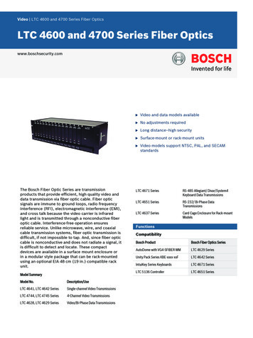
4CHAPTER IITHEORETICAL BACKGROUNDA. Optical fibersOver the past few decades the demand for higher capacity, higher speedtransmission lines for communication has fueled the expansion of the fiber opticindustry. As the enabling technology for the internet and long haul communicationlines, fiber optic technologies benefit us all.Figure 1. Optical fiber structure [3]Optical fibers consist of three main components: the core, the cladding and theouter buffer, as shown in Figure 1. The core consists of highly pure glass, usuallyfused silica (SiO2) doped with germania (GeO2).The core is surrounded by the
5cladding glass, generally pure fused silica, which has a lower refractive index than thecore, as required for waveguiding. Finally an outer buffer layer made of a polymermaterial is used for structural integrity and protection of the underlying glass. Theouter buffer, which has the highest refractive index of all the layers, generally absorbslight propagating in the cladding in a relatively short distance (tens of meters or less).With the higher index core and lower index cladding, light coupled into the coreat one end of the fiber can propagate through tens or even hundreds of km of fiberwithout measurable loss due to leakage into the cladding. Trapping of the light in thecore is explained by the principle of total internal reflection (TIR).For a large-coremultimode fiber the condition for TIR is given by Θair ΘC, with Θair the anglebetween an incident light ray and the fiber axis, andsin ΘC n12 n 2 2(1)where n1 and n2 are the refractive indices of the transmitting region and claddingrespectively as shown in Figure 2, and it is assumed that the incident light propagatesin air (n 1).n2n1claddingcoreΘ airincident lightrayFigure 2. Light ray entering the core of an optical fiber
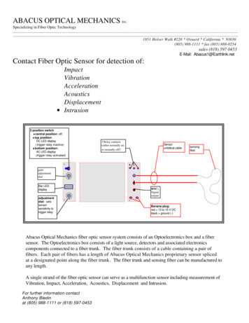
6Optical fibers in general are divided into two main categories: single mode andmulti-mode. The two types of fiber are distinguished by their relative core diametersand have different applications. Multimode fibers have much larger core diameters(50-100 µm) to allow many modes to propagate at one time, while single mode fibercores are much smaller (8-10 µm) allowing only one mode to be transmitted. Thedesignation of single/multimode fiber is determined by the parameter V, given byV 2πaλ22n 1 n2 ,(2)where a is the radius of the fiber core, λ is the wavelength, and n1 and n2 are therefractive indices of the core and cladding, respectively. A single mode fiber has a Vvalue less than 2.405, therefore anything with a larger V value is consideredmultimode. For interferometric sensing as in this research, single mode fibers arepreferable because the propagating light wave is characterized by a single value of thephase.An important factor in the intrusion sensor system is the fiber’s attenuation.Figure 3 depicts the attenuation vs. wavelength of a single mode fused silica fiber.Attenuation peaks due to water molecules in the fiber create three main windows ofoperation centered around 850 nm, 1300 nm, and 1550 nm. The laser used in theseexperiments operates at 1555.6 nm, in the third “operational window”, due to itscompatibility with erbium doped fiber amplifiers (EDFAs). (It should be noted that intoday’s best fibers the 1380 nm water peak has been virtually eliminated.)
7Figure 3. Spectral attenuation in a fused silica fiber [4]B. Phase response to temperature changes in fiberFactors which can affect the phase of light propagating in a fiber include staticpressure, acoustic wave pressure, strain, and thermal fluctuations. Thermal variationscan have a major effect on the phase of the light signal and must be accounted for inthe sensor design [5]. The phase, φ, and phase change, φ, of an optical signal in afiber of length L are represented in (3) and (4) asφ φ 2πnL,λ(3)2π (nL),λ(4)
8where n is the effective refractive index of the fiber mode and λ is the free-spacewavelength of light. The effect of a temperature change, Τ, on nL is given by (nL) (n L n L ) T . T T(5)The sensitivity to temperature is a major concern if looking at the phase effects inlong stretches of fiber. For a silica fiber which has a very low thermal expansioncoefficient, the effect of refractive index change is dominant - over 10 times greaterthan the effect of length change. To minimize thermal fluctuations it is imperative thata considerable effort to insulate the interferometers against temperature changes beundertaken to ensure accurate frequency drift data.C. Phase shifts in a buried fiberThe sensitivity of a buried fiber optic cable to the pressure of an intruder crossingover it is a key issue in achieving a practical intrusion detection system. Even though itis possible to calculate the phase shift due to lateral pressure on a fiber, suchcalculations do not adequately account for the influence of the cable itself and thesurrounding soil composition and conditions. Thus, in previous work, experimentswere undertaken at Texas A&M to measure the phase change produced by a weight onthe ground above a buried fiber cable.In one series of experiments, the phase shift induced by pressure on a fiber cableburied in a sand box was investigated. The buried cable was spliced into one arm of anall-fiber Mach-Zehnder interferometer, and the phase shift was determined by
9monitoring the pressure-induced phase fluctuations. A box with dimensions 30 cm x10 cm (approximately the size of a human foot) was placed directly above the buriedcable, and weights were added to the box to produce a π-radian phase shift asdetermined by monitoring the interferometer output power. For a depth of 20 cm a 60kg intruder produced a phase change of about 6π radians, while for a 40 cm depth thephase change was about 2.5 π radians. As expected, for a given burial depth theinduced phase change was found to be close to a linear function of the applied weight[6].Further investigations were made to determine if it was possible to avoiddetection by stepping over the sensor cable. Fiber cable was buried at a depth of 30cm in clay soil and it was found that a 60 kg intruder produces a π-radian phase shiftwithin 2 meters on either side of the cable location.D. Rayleigh scattering in optical fibersThe phenomenon of Rayleigh scattering accounts for nearly all ( 96%) of theattenuation in today’s fibers [7]. As light passes through the fiber it is scattered byrandom microscopic variations in the refractive index formed during the fiber drawingprocess, as in Figure 4. The light scatters in all directions, but a small fraction of thescattered light propagates in the reverse direction and is guided in the fiber core.
10Figure 4. Rayleigh scatter in optical fiber [2]The light that is backscattered towards the light source can be used in optical timedomain reflectometry to monitor attenuation throughout the fiber length. Rayleigh lossdecreases by 1/λ4 with increasing wavelength throughout the visible and near-infraredspectral regions, to about 1550 nm wavelength, beyond which the attenuation increasesrapidly due to optical absorption resulting from the excitation of phonons in the fibermaterial. The minimum fiber loss at any wavelength is about 0.2 dB/km for 1550 nmlight.E. Mach Zehnder interferometer designInterferometers are used for making measurements by determining relative phaseshifts in optical path lengths. For this project, an unbalanced Mach Zehnderinterferometer (MZI) was chosen.The MZI splits an input light beam into twodifferent optical paths, and then recombines the two beams after traveling their two
11separate path lengths. In the case of the unbalanced MZI one path is lengthened as inFigure 5, adding a delay component to the interference.Reference ArmDetectorLaserPZTSensing ArmFigure 5. Unbalanced Mach ZehnderThe detected output waveform represents the interference of light emitted by the laserat time t with light emitted at time t τ, with τ given byτ n g Lc,(6)with ng the group refractive index of the fiber mode, L the fiber length difference inthe interferometer, and c the free-space speed of light. Thus, with ng 1.46, L 200m (as in the present work) and c 3 x 10⁸ m/sec,τ 1.46 * 200 0.97 µ sec .3 *10 8(7)The interferometer output signal indicates the rate of frequency drift in the laser, withone complete period (fringe) - indicative of a 2π radian relative phase shift corresponding to a frequency change of 1/τ. In the present case, one fringe represents a
12laser frequency drift of 1.03 MHz. The photodetector signal received at the outputcoupler of the MZIs is digitized by a data acquisition card and stored in the memory ofa personal computer. Once in the computer, the drift rate data can be analyzed andplotted.F. Laser linewidthThe linewidth or spectral width of the laser light is an intrinsic property that canaffect the ability to utilize the coherence of the laser light [8]. The difference betweenthe φ-OTDR and the conventional OTDR is in the light source linewidth.Theconventional OTDR uses a current-modulated laser diode with a spectral width 1/τ,with τ the laser pulse width. Thus, if τ 1 nsec, corresponding to 10 cm spatialresolution, then the spectral width of the laser pulses is 1 GHz. (From a practicalstandpoint, since OTDRs generally use multimode Fabry-Perot lasers, the spectralwidth is in the hundreds of GHz range). The broad laser spectrum ensures a smoothOTDR trace which depends on the amplitude but not relative phases of the waveswhich contribute to the Rayleigh-backscattered light. On the other hand, the φ-OTDRrequires a light source spectral width 1/τ so that phase changes along the fiber willstrongly affect the observed response. As an example, if τ 1 µsec, corresponding to a100 m spatial resolution, then the spectral width should ideally be 1 MHz.
13G. Frequency drift in lasersThe availability of a laser with narrow instantaneous linewidth and very lowfrequency drift is the key to a successful demonstration of the intrusion sensor. Asmentioned above, if the instantaneous spectral width of the laser is 1/τ, with τ thewidth of the laser pulse, coherent effects will disappear and a smooth OTDR tracewhich is insensitive to phase changes will be observed. Even if the instantaneousspectral width is 1/τ, the laser will still not be satisfactory if its frequency driftssignificantly as the intrusion-induced pressure change is occurring.Suppose, forexample, that a slow-moving intruder produces a phase perturbation in lightpropagating in the fiber which goes from 0 to π-radian in 1 second. A frequency drift inthe laser of 1/τ which occurs during 1 sec will produce optical power changes in eachtime bin on the order of the change which would result from this intruder-inducedphase shift. For that reason, it is important that the frequency drift be 1/τ over thetime frame during which a dynamic change occurs. Thus, in the present example withτ 1 µsec and the perturbation occurring over a one second time interval, the laserfrequency drift rate should be much less than 1 MHz/sec.H. Erbium doped fiber amplifiersWith the increased use of optical fiber throughout the world came the need toboost the signal over long stretches of fiber. Prior to the advent of optical amplifiersthe only way to boost signal levels in fiber optic communication systems were optical
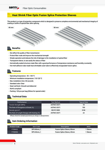
14to electrical to optical (OEO) conversion through the use of optoelectronic repeaters[9]. However, each optoelectronic repeater was expensive and one was required foreach wavelength-division-multiplexed (WDM) channel in an optical communicationsystem. Various optical amplifier technologies have been developed, includingsemiconductor optical amplifiers, rare-earth-doped, fiber amplifiers, and Brillouin andRaman amplifiers, each of which has its own advantages and disadvantages [10]. Ofall the candidates, the erbium doped fiber amplifier (EDFA) has emerged as thetechnology of choice for optical telecommunication.Figure 6. Operation of EDFA [9]The EDFA operates by injecting pump light into doped fiber to boost electrons inEr3 atoms from the ground state to an excited state, as in Figure 6. Erbium ions (Er3 )have a lasing transition at 1.5 µm, which happens to coincide with the spectral regionof lowest loss in a silica fiber. Furthermore the two strongest absorption bands in
15erbium correspond to wavelengths of 980 nm and 1480 nm; wavelengths at whichsemiconductor laser pump diodes can be fabricated with sizeable output powers [11].EDFAs, which can simultaneously boost signal levels in many WDM channels in asingle fiber, are widely used for signal regeneration in optical fiber communicationsystems.I. OTDR configurationThe optical time domain reflectometer (OTDR), initially demonstrated over twodecades ago [12-14], is now widely used for locating breaks and other anomalies infiber optic links and networks. In such a system, light pulses from a semiconductorlaser are injected into one end of a fiber, and the light returned from the fiber byRayleigh backscattering is monitored with a photodetector, as in Figure. 7. The OTDRdetects the presence and location of perturbations which affect the intensity of the lightreturned from the fiber, but does not in general respond to phase modulation of thelight. The spectral width of the modulated laser is very broad (GHz to THz range), sothat fluctuations in the return signal due to interference of backscattered componentsfrom different parts of the fiber are avoided. When present to a noticeable extent,coherent effects represent an undesirable source of noise in an OTDR trace [15].
16Figure 7. Optical time-domain reflectometer (OTDR)J. Configuration for φ-OTDR intrusion sensorIn the perimeter security sensor investigated here, phase changes resulting fromeither the pressure of the intruder on the ground immediately above the buried fiber orfrom seismic disturbances in the vicinity are sensed by a phase-sensitive optical timedomain reflectometer (φ-OTDR) [15,16]. The sensitivity of conventional OTDRs tosmall perturbations is orders of magnitude too low for this application because of thebroad spectrum of the light source. For the φ-OTDR, light pulses from a continuouswave laser with a narrow (kHz-range) spectral width are gated into one end of the fibervia a pulsed intensity modulator, and the backscattered light from the fiber is
17monitored with a photodetector. As with the conventional OTDR, the φ-OTDR trace isa plot of returned optical power vs. time. Phase sensitivity results from coherentaddition of amplitudes of the light backscattered from different parts of the fiber whicharrive simultaneously at the photodetector. In contrast to the conventional OTDR, theφ-OTDR requires a laser with minimal frequency drift as well as narrow instantaneouslinewidth. The Er:fiber laser is an attractive candidate because it emits in the spectralregion where silica fiber losses are at a minimum, it can be used with Er:fiberamplifiers to achieve high average and pulsed power levels, and it can be configured toemit in a single longitudinal mode for narrow linewidth operation.Figure 8. Configuration for φ-OTDR intrusion sensor [16]
18The φ OTDR intrusion sensor is illustrated schematically in Figure 8. Lightfrom the frequency-stabilized Er:fiber laser passes through an integrated opticalmodulator, which gates an optical pulse through a 3-dB coupler and into a multikilometer stretch of buried fiber optic cable.Rayleigh backscattered light passesthrough the coupler and is collected by a photodetector. If the laser emits a singleoptical frequency which does not change with time, and no optical phase changes occurover the fiber length, the φ OTDR traces will be the same from one laser pulse to thenext. However, when an intruder causes a phase shift to occur, the trace will beaffected at a time corresponding to the location of the intrusion. By subtracting themost recent trace from a previous stored trace, the intruder can be detected and located.When a short light pulse is coupled into the fiber, the duration T of the returnpulse will be given byT 2 Ln gc,(8)with L the length of the fiber, ng the refractive index of the fiber and c the free spacespeed of light. For a silica fiber with ng 1.46, it is calculated that T 9.73L with T inµs and L in km. Thus, for a 12 km path length, the duration of the return signal is117µs. With a simulated disturbance at the 2 km point the phase shift would bedetected 20 µs into the trace.Previous theoretical calculations on such a φ OTDR intrusion sensor conductedby Texas A&M [16] predicts a dependence of range resolution on detection range forsuch a sensor given by Figure 9.
range resolution 35.0range (km)Figure 9. Simulated dependence of range resolution on range in fiber [16]For perimeters as large as 35 km the theoretical analysis suggest resolution ofintrusion points as small as 100 m. Factors such as environmental conditions will havean effect on such calculations, but with sufficient insulation this sensor system willhave monitoring capabilities that far surpass many of today’s resolution standards forlong-range perimeters.
20CHAPTER IIIEXPERIMENTAL PROCEDURESA. Laser stabilizationFor the operation of the fiber intrusion sensor, a highly stable light source isneeded for transmission throughout the perimeter of buried fiber to achieve accuratemeasurement. In previous work in the Electrical Engineering Department at TexasA&M, a narrow line, low-drift rate erbium-doped fiber laser (EDFL), Figure 10, wasdeveloped [15] and applied to the first laboratory demonstration of the φ-OTDR [16].However, substantial i
A distributed fiber optic intrusion sensor capable of detecting intruders from the pressure of their weight on the earth's surface was investigated in the laboratory and in field tests. The presence of an intruder above or in proximity to the buried sensor induces a phase shift in light propagating along the fiber which allows for the detection
![Fiber Optic - Perimeter Intrusion Detection System [Fopids]](/img/57/foss-presentation.jpg)