Transcription
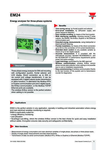
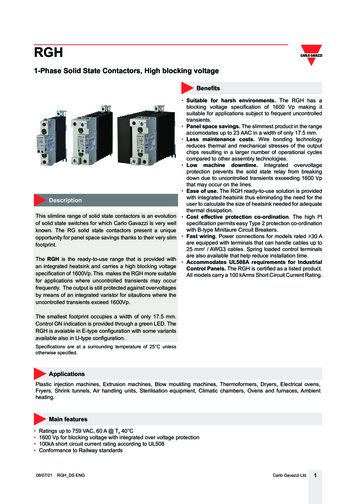
RGHRGH1-Phase Solid State Contactors, High blocking voltageBenefitsDescriptionThis slimline range of solid state contactors is an evolutionof solid state switches for which Carlo Gavazzi is very wellknown. The RG solid state contactors present a uniqueopportunity for panel space savings thanks to their very slimfootprint.The RGH is the ready-to-use range that is provided withan integrated heatsink and carries a high blocking voltagespecification of 1600Vp. This makes the RGH more suitablefor applications where uncontrolled transients may occurfrequently. The output is still protected against overvoltagesby means of an integrated varistor for sitautions where theuncontrolled transients exceed 1600Vp. Suitable for harsh environments. The RGH has ablocking voltage specification of 1600 Vp making itsuitable for applications subject to frequent uncontrolledtransients. Panel space savings. The slimmest product in the rangeaccomodates up to 23 AAC in a width of only 17.5 mm. Less maintenance costs. Wire bonding technologyreduces thermal and mechanical stresses of the outputchips resulting in a larger number of operational cyclescompared to other assembly technologies. Low machine downtime. Integrated overvoltageprotection prevents the solid state relay from breakingdown due to uncontrolled transients exceeding 1600 Vpthat may occur on the lines. Ease of use. The RGH ready-to-use solution is providedwith integrated heatsink thus eliminating the need for theuser to calculate the size of heatsink needed for adequatethermal dissipation. Cost effective protection co-ordination. The high I²tspecification permits easy Type 2 protection co-ordinationwith B-type Minitaure Circuit Breakers. Fast wiring. Power connections for models rated 30 Aare equipped with terminals that can handle cables up to25 mm2 / AWG3 cables. Spring loaded control terminalsare also available that help reduce installation time. Accommodates UL508A requirements for IndustrialControl Panels. The RGH is certified as a listed product.All models carry a 100 kArms Short Circuit Current Rating.The smallest footprint occupies a width of only 17.5 mm.Control ON indication is provided through a green LED. TheRGH is avaiable in E-type configuration with some variantsavailable also in U-type configuration.Specifications are at a surrounding temperature of 25 C unlessotherwise specified.ApplicationsPlastic injection machines, Extrusion machines, Blow moulding machines, Thermoformers, Dryers, Electrical ovens,Fryers, Shrink tunnels, Air handling units, Sterilisation equipment, Climatic chambers, Ovens and furnaces, Ambientheating.Main features Ratings up to 759 VAC, 60 A @ TA 40 C1600 Vp for blocking voltage with integrated over voltage protection100kA short circuit current rating according to UL508Conformance to Railway standards08/07/21RGH DS ENGCarlo Gavazzi Ltd.1
RGHOrder codeRGH1AEnter the code option instead GH DS ENG. Refer to the selection guide section for valid part numbers.DescriptionCommentsSolid State Relay (RG)With integrated heatsink1-pole switchingZero Cross switching (ZC)Rated voltage: 42-660 VACRated voltage: 42-759 VACControl voltage: 4-32 VDCControl voltage: 20-275 VAC, 24-190 VDCRated current: 23 AAC (6600 A²s)Rated current: 30 AAC (6600 A²s)Rated current: 40 AAC (6600 A²s)Rated current: 60 AAC (6600 A²s)Screw connection for control terminalsPluggable spring-loaded connection for control terminalsScrew connection for power terminalsBox clamp connection for power terminalsContactor configurationSSR configuration1600 Vp blocking voltage17.5 mm wide, low depth22.5 mm wide35 mm wide70 mm wideApplicable only to: RGH.15, 31Applicable only to: RGH.41, 60Applicable only to: RGH.41, 60Single packagingBulk packaging of 20 pcs.Applicable only to: RGH.15Carlo Gavazzi Ltd.2
RGHSelection guideFor E - type configuration:Rated operational current @ 40 CRatedvoltage,Blockingvoltage,Switchingmode600 VAC,1600 VpZC690 VAC,1600 VpZC23 AAC(6600 A2s)30 AAC(6600 A2s)17.5 mm, low depth22.5 mm35 mm70 mm4 - 32 5 VAC,24-190 31MKERGH1A60A41KGERGH1A60A41MGERGH1A60A60KGE-4- 32 VDC--RGH1A69D41KGERGH1A69D60KGE20-275 VAC,24-190 VDC--RGH1A69A41KGERGH1A69A60KGEControlvoltage40 AAC(6600A2s)60 AAC(6600 A2s)Product widthFor U - type configuration:Rated operational current @ 40 CRatedvoltage,Blockingvoltage,Switchingmode600 VAC,1600 VpZCKKE:KGE:MKE:MGE:KGU:40 AAC(6600A2s)60 AAC(6600 A2s)----35 mm70 mm4 - 32 VDC--RGH1A60D41KGURGH1A60D60KGU20-275 VAC,24-190 VDC--RGH1A60A41KGURGH1A60A60KGUControlvoltageinput terminals screwinput terminals screwinput terminals pluggable springinput terminals pluggable springinput terminals screwProduct widthoutput terminals screwoutput terminals box clampoutput terminals screwoutput terminals box clampoutput terminals box clampCarlo Gavazzi compatible componentsDescriptionComponent codeNotesControl PlugsRGM25Pack of 10 spring loaded control plugsCarlo Gavazzi further readingInformationWhere to find es/PIM/DATASHEET/ENG/rgc.pdfSolid state contactor, RGC with 'E' - n.com/images/PIM/DATASHEET/ENG/rgc u.pdfSolid state contactor, RGC with 'U' - typeconfiguration08/07/21RGH DS ENGCarlo Gavazzi Ltd.3
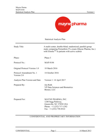
1/L1A1 A2-LED2/T1A1 LEDA22/T1Element1/L12/T1A1 , A2LEDHeatsinkPEComponentPower connectionPower connectionControl connectionON indicatorIntegrated heatsinkProtective EarthFunctionMains connectionLoad connectionTerminals for control voltageIndicates presence of control voltageDIN rail mounting (panel mounting also possible)Connection for Protective Earth, PE screw not provided with RGHNote: For U- type configuration please refer to Dimensions and Terminal layout sections.08/07/21RGH DS ENGCarlo Gavazzi Ltd.4
RGHFeaturesGeneral dataMountingPA66 or PA6 (UL94 V0), RAL7035Glow wire ignition temperature and Glow wire flammability index conform toEN 60335-1 requirementsDIN rail (panel mount also possible)Touch ProtectionIP20Overvoltage CategoryIII, 6 kV (1.2/50 μs) rated impulse withstand voltageInput and Output to Case:4000 VrmsInput to Output:4000 VrmsRGH.15:approx. 260 gRGH.31:approx. 375 gRGH.41:approx. 515 gRGH.60:approx. 972 gMaterialIsolationWeightPerformanceOutput specificationsMax. operational current1:AC-51 @ Ta 25 CMax. operational current1:AC-51 @ Ta 40 CMax. operational current1,3:AC-53a @ Ta 40 COperational frequency rangeOutput protectionLeakage current @ rated voltageMinimum operational currentRepetitive overload current(Motor rating) UL508: Ta 40 C,tON 1 s, tOFF 9 s, 50 cyclesNon-repetitive surge current(ITSM), t 10 msI²t for fusing (t 10 ms), minimumNo. of motor starts per hour2(x 6, Tx 6s, F 50%) @ 40 CPower factorCritical dV/dt (@Tj init 40 C)RGH.15RGH.31RGH.41RGH.6023 AAC30 AAC49 AAC75 AAC23 AAC30 AAC40 AAC60 AAC5 AAC10 AAC13 AAC18 AAC45 to 65 HzIntegrated varistor4 3 mAAC400 mAAC400 mAAC400 mAAC400 mAAC51 AAC84 AAC126 AAC144 AAC1150 Ap1150 Ap1150 Ap1150 Ap6600 A²s6600 A²s6600 A²s6600 A²s30 0.5 at rated voltage1000 V/μs1. Refer to Current derating curves2. Overload profile for AC-53a;Ie: AC-53a: xIe-Tx: F-S, where Ie nominal current (AC-53a AAC), xIe overload current factor, Tx duration of overloadcurrent (s), F duty cycle (%), S number of starts per hour. Example; 5A: AC-53a: 6 - 6 : 50 - 30 max. 30 starts for theRGH.15 with an overload profile of 30A for 6 seconds with a duty cycle of 50%3. The AC53a value depends on the specific overload profile and can change based on the overload characteristics. For example:the RGH.15 is rated with an AC53a rating of 16A for an overload profile of: 16A: AC53a: 5-1 : 50-10the RGH.31 is rated with an AC53a rating of 16A for an overload profile of: 16A: AC53a: 6-1 : 75-104. Varistor on output is not included in the RGH1A69.models08/07/21RGH DS ENGCarlo Gavazzi Ltd.5
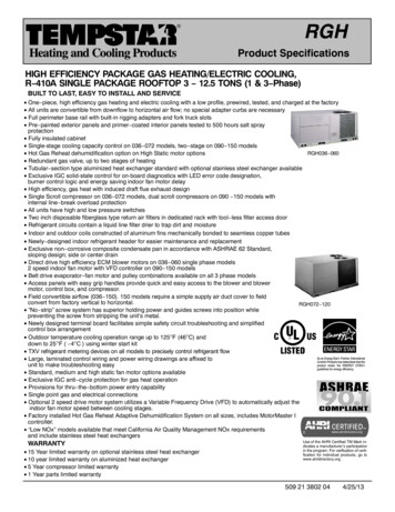
RGHOutput voltage specificationsOperational voltage rangeBlocking voltageInternal varistorRGH1A60.RGH1A69.42-600 VAC, 10% -15% on max42-690 VAC5, 10% -15% on max680 V1600 Vp-5: 690 VAC refers to the line to line voltageMotor ratings: HP (UL508) / kW (EN/IEC 60947-4-2) @ 40 CRGH.15RGH.31RGH.41RGH.60115 VAC1/3HP / 0.18kW¾HP / 0.37kW1½HP / 0.56kW2HP / 0.75kW230 VAC1HP / 0.37kW2HP / 1.1kW3HP / 1.5kW3HP / 1.5kW400 VAC2HP / 0.75kW3HP / 1.5kW5HP / 2.2kW5HP / 4kW480 VAC3HP / 1.1kW5HP / 2.2kW7½HP / 3.7kW7½HP / 4kW600 VAC3HP / 1.5kW5HP / 3.7kW10HP / 4kW10HP / 5.5kW690 VAC- / 1.5kW- / 3.7kW- / 4kW- / 5.5kWInputsRGH.D.Control voltage range6Pick-up voltageDrop-out voltageMaximum reverse voltageMaximum response timeResponse time drop-outInput current @ 40 CRGH.A.20-275 VAC,24 (-10%) -190 VDC20 VAC/DC5 VAC/DC-4 - 32 VDC3.8 VDC1.0 VDC32 VDC0.5 cycle 500 μs @ 24 VDC2 cycles @ 230 VAC/110 VDC0.5 cycle 40 ms0.5 cycle 500 μs @ 24 VDC@ 230 VAC/110 VDCSee diagrams below6. DC control to be supplied by class 2 power source according to UL1310Input current vs. input voltageRGH.DRGH.ADC input current vs input voltage08/07/21RGH DS ENGAC input current vs input voltageCarlo Gavazzi Ltd.6
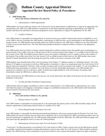
RGHOutput power dissipation10090Power dissipation in 85Load current in AACrmsCurrent derating90Load current in 07/210RGH DS ENG102030405060Surrounding ambient temperature in C7080Carlo Gavazzi Ltd.7
RGHDerating vs. spacing curves28RGH.15.Load Current in AAC2420160mm125mm10mm & over8Stand alone unit4001020304050607080Surrounding Ambient Temperature in oCLoad Current in AACRGH.31.0mm5mm10 mm & overStand alone unitSurrounding Ambient Temperature in CLoad Current in AACRGH.41.0mm10 mm & overStand alone unitSurrounding Ambient Temperature in CLoad Current in AACRGH.60.0mm10 mm & overStand alone unitSurrounding Ambient Temperature in C08/07/21RGH DS ENGCarlo Gavazzi Ltd.8
RGHCompatibility and conformance7ApprovalsStandards complianceLVD:EMCD:UL:cUL:VDE:EN/IEC 60947-4-2, EN/IEC 60947-4-3EN/IEC 60947-4-3UL508, E172877, NMFTC22.2 No. 14, E172877, NMFT7VDE 0660-109UL short circuit current rating100k Arms (refer to short circuit current section, Type 1 – UL508)7: 690 VAC version is CE marked onlyElectromagnetic compatibility (EMC) - ImmunityElectrostatic discharge (ESD)Radiated radio frequencyElectrical fast transient (burst)Conducted radio frequencyElectrical surge8Voltage dipsVoltage interruptionsEN/IEC 61000-4-28 kV air discharge, 4 kV contact (PC1)EN/IEC 61000-4-310 V/m, from 80 MHz to 1 GHz (PC1)10 V/m, from 1.4 to 2 GHz (PC1)10 V/m, from 2 to 2.7 GHz (PC1)EN/IEC 61000-4-4Output: 2 kV, 5 kHz (PC1)Input: 1 kV, 5 kHz (PC1)EN/IEC 61000-4-610 V/m, from 0.15 to 80 MHz (PC1)EN/IEC 61000-4-5Output, line to line: 1 kV (PC1)Output, line to earth: 2 kV (PC1)Input, line to line, 1kV (PC2)Input, line to earth, 2kV (PC2)EN/IEC 61000-4-110% for 0.5, 1 cycle (PC2)40% for 10 cycles (PC2)70% for 25 cycles (PC2)80% for 250 cycles (PC2)EN/IEC 61000-4-110% for 5000 ms (PC2)8: An external varistor, S20K750, needs to be connected across the mains supply for the RGH1A69. modelsElectromagnetic compatibility (EMC) - EmissionsRadio interference fieldemission (radiated)EN/IEC 55011Class A: from 30 to 1000 MHzRadio interference voltageemissions (conducted)EN/IEC 55011Class A: from 0.15 to 30 MHz(External filter may be required - refer to Filtering section)08/07/21RGH DS ENGCarlo Gavazzi Ltd.9
RGHAdditional conformance to railway standardsApplicable to variantsRGHAdditional conformancespecific to railway applicationsEN 50155EN 45545-2EN 50121-3-2HL1, HL2 for requirement R23HL1 for requirement R22Hazardous level conformanceaccording to EN 45545-2Operating temperature classaccording to EN 50155Vibration and shockAdditional EMC conformanceRadiated radio frequencyimmunityPower quality measurementOT3 (-25 C to 70 C )EN 61373 Category 1, Class Baccoding to EN 50121-3-2EN/IEC 61000-4-320 V/m, from 80 MHz to 1 GHz (PC1)10 V/m, from 1.4 to 2 GHz (PC1)5 V/m, from 2 to 2.7 GHz (PC1)3V/m, 5.1 - 6 GHz (PC1)EN/IEC 61000-4-3050 Hz - 2 kHz, 8% THD (PASS)Filter connection diagram3 Phase1 PhaseL1SSRL2SSRLOADSSRL3RdRdRdNRd 1MΩ, 0.5WFilter has to be connectedacross both LOAD and SSRFilteringPart numberSuggested filter for EN 55011 ClassA complianceMaximum heater currentRGH1A60.15220 nF / 760V / X120 AACRGH1A60.31220 nF / 760V / X130 AACRGH1A60.41330 nF / 760V / X1330 nF / 760V / X1680 nF / 760V / X140 AAC40 AAC65 AACRGH1A60.60Note: Control input lines must be installed together to maintain products’ susceptability to Radio Frequency interference. Use of AC solid state relays may, according to the application and the load current, cause conducted radio interferences. Use of mainsfilters may be necessary for cases where the user must meet E.M.C requirements. The capacitor values given inside the filteringspecification tables should be taken only as indications, the filter attenuation will depend on the final application. This product has been designed for Class A equipment. Use of this product in domestic environments may cause radio interference, inwhich case the user may be required to employ additional mitigation methods. Performance Criteria 1 (PC1): Performance Criteria 2 (PC2): Performance Criteria 3 (PC3):08/07/21RGH DS ENGNo degradation of performance or loss of function is allowed when the product is operated as intended.During the test, degradation of performance or partial loss of function is allowed. However when thetest is complete the product should return operating as intended by itself.Temporary loss of function is allowed, provided the function can be restored by manual operation ofthe controls.Carlo Gavazzi Ltd.10
RGHEnvironmental specificationsOperating temperature-40 C to 80 C (-40 F to 176 F)Storage temperature-40 C to 100 C (-40 F to 212 F)Relative humidity95% non-condensing @ 40 CPollution degree2Installation altitude0-1000 m. Above 1000 m derate linearly by 1% of FLC per 100 m up to a maximumof 2000 mVibration resistance2g / axis (2-100Hz, IEC 60068-2-6, EN 50155, EN 61373)Impact resistance15/11 g/ms (EN 50155, EN 61373)EU RoHS compliantYes25China RoHSThe declaration in this section is prepared in compliance with People’s Republic of China Electronic Industry Standard SJ/T11364-2014: Marking for the Restricted Use of Hazardous Substances in Electronic and Electrical Products.Toxic or Harardous Substances and ElementsPart um(Cr(Vl))Polybrominated biphenyls(PBB)Polybrominated diphenylethers (PBDE)Power UnitAssemblyxOOOOOO: Indicates that said hazardous substance contained in homogeneous materials fot this part are below the limitrequirement of GB/T 26572.X: Indicates that said hazardous substance contained in one of the homogeneous materials used for this part is abovethe limit requirement of GB/T ��含有的该有害物低于GB/T 26572的限定。X: �GB/T 26572的限定。08/07/21RGH DS ENGCarlo Gavazzi Ltd.11
RGHShort circuit protectionProtection Co-ordination, Type 1 vs Type 2:Type 1 protection implies that after a short circuit, the device under test will no longer be in a functioning state. In Type 2co-ordination the device under test will still be functional after the short circuit. In both cases, however the short circuit hasto be interrupted. The fuse between enclosure and supply shall not open. The door or cover of the enclosure shall not beblown open. There shall be no damage to conductors or terminals and the conductors shall not separate from terminals.there shall be no breakage or cracking of insulating bases to the extent that the integrity of the mounting of live parts isimpaired. Discharge of parts or any risk of fire shall not occur.The product variants listed in the table hereunder are suitable for use on a circuit capable of delivering not more than100,000 Arms Symmetrical Amperes, 600 Volts maximum when protected by fuses. Tests at 100,000 A were performedwith Class J fuses, fast acting; please refer to the table below for maximum allowed ampere rating of the fuse. Use fusesonly.Tests with Class J fuses are representative of Class CC fuses.Protection co-ordination Type 1 according to UL 508Part No.Prospective shortcircuit current[kArms]RGH1A60.15RGH1A60.31RGH1A60.41Max fuse size [A]Class30J or CC40JVoltage [VAC]100Max. 600RGH1A60.60Protection co-ordination Type 2 (IEC/EN 60947-4-2/ -4-3)Part No.Prospectiveshort circuitcurrent [kArms]Ferraz Shawmut (Mersen)SibaMax fusesize [A]Max fusesize [A]Part numberPart numberMax. voltage[VAC]50 194 20.10066050 197 /07/21RGH DS ENGCarlo Gavazzi Ltd.12
RGHProtection co-ordination Type 2 with Minature Circuit Breakers (M.C.B.s)Solid State Relay typeABB Model no. forZ - type M. C. B.(rated current)ABB Model no. forB - type M. C. B.(rated current)Wire cross sectional area[mm2]Minimum length of Cuwire conductor [m]9RGH.15RGH.31RGH.41RGH.60(6600 A2s)S201 - Z20 (20A)S201-B10 (10A)S201 - Z32 (32A)S201-B16 (16A)S202 - Z20 (20A)S202-B10 (10A)S202 - Z32 (32A)S202-B16 (16A)S202 - Z50 (50A)S202-B25 14.822.237.09. Between MCB and Load (including return path which goes back to the mains)Note: A prospective current of 6 kA and a 230/400 V power supply is assumed for the above suggested specifications. For cables withdifferent cross section than those mentioned above please consult Carlo Gavazzi's Technical Support Group.S201 models refer to 1-pole M.C.B., S202 models refer to 2-poles M.C.B.08/07/21RGH DS ENGCarlo Gavazzi Ltd.13
RGHDimensions4.54.4109.5 [4.31’’]924.45.4Ø5.444.535.590100.4110 [4.33’’]4.590100.4110 [4.33’’]98.5 3.83.24.4844.535.5147 [5.78’’]129.54.54.45.45.4Ø4.5Ø136 [5.35’’]90100.4110 [4.33’’]5135.517.8 [0.70’’]RGH1A.31MKE4.4RGH1A.31KKE4.4817.8 [0.70’’]3.243.843.890100.4110 [1.33’’]3.24.484.4817.817.822.5 [0.89’’]22.5 [0.89’’]44.543.7147 [5.78’’]129.54.55.43.290100.4110 [4.33’’]5.44.44.5.4136 .890100.4110 [4.33’’]3.284.417.835.6 [1.40’’]84.417.835.6 [1.40’’]Housing width tolerance 0.5mm, -0mm as per DIN 43880. All other tolerances /- 0.5mm.Dimensions in mm.08/07/21RGH DS ENGCarlo Gavazzi Ltd.14
RGHDimensions - continuedRGC.60KGE136 [5.35’’]5143.717.85.44.54Ø4.43.890100.4110 [4.33’’]3.2817.8RGH1A.41KGU4.443.270 [2.76’’]817.84.4RGH1A.60KGU5.417.84.44.5136 [5.35’’]5143.73.24.4817.835.6 [1.40’’]110.490110 [4.33’’]110 .270 [2.76’’]817.84.4Housing width tolerance 0.5mm, -0mm as per DIN 43880. All other tolerances /- 0.5mm.Dimensions in mm.08/07/21RGH DS ENGCarlo Gavazzi Ltd.15
RGHTerminal layout1L11L11L11L1CARLO GAVAZZIL1A2T1ONA12RG Solid State SwitchRG Solid State L1:2/T1:A1( ains supply connectionLoad connectionPositive control signalControl groundProtective EarthConnection diagramL1L2/N*ControlinputLoad* depends on system requirements08/07/21RGH DS ENGCarlo Gavazzi Ltd.16
RGHFunctional diagramDC controlA1( )T1REGULATIONZCA2( - )L1AC control )A1( T1REGULATIONZCA2( - )L1Note: Varistor on output is not included in the RGH1A69.modelsInstallationY1 50mmY1 50mmRGCRGHRGCXXRGCRGHRGCXX Referto Refer toX Y2 Derating vs.Derating vs.100mmSpacing CurvesSpacing CurvesXY2 100mmRGCRGHMounting on DIN railMounting on DIN railRGCDismounting from DIN railDismounting from DIN rail50mm50mm08/07/21RGH DS ENGCarlo Gavazzi Ltd.17
RGHConnection SpecificationsPower connectionsTerminals1/L1, 2/T1ConductorsUse 75 C copper (Cu) conductorsRGH.KKE, RGH.MKERGH.KGE, RGH.MGE, RGH.KGUConnection typeM4 screw with captivated washerM5 screw with box clampStripping length12 mm11 mmRigid (solid & stranded)UL/cUL rated data2x 2.5 – 6.0 mm²2x 14 – 10 AWG1x 2.5 – 6.0 mm²1x 14 – 10 AWG1x 2.5 – 25.0 mm²1x 14 – 3 AWGFlexible with end sleeve2x 1.0 – 2.5 mm²2x 2.5 – 4.0 mm²2x 18 – 14 AWG2x 14 – 12 AWG1x 1.0 – 4.0 mm²1x 18 – 12 AWG1x 2.5 – 16.0 mm²1x 14 – 6 AWGFlexible without endsleeve2x 1.0 – 2.5 mm²2x 2.5 – 6.0 mm²2x 18 – 14 AWG2x 14 – 10 AWG1x 1.0 – 6.0mm²1x 18 –10 AWG1x 4.0 – 25.0 mm²1x 12 – 3 AWGTorque specificationsPosidrive bit 2UL: 2.0 Nm (17.7 lb-in)IEC: 1.5 – 2.0 Nm (13.3 – 17.7 lb-in)Posidrive bit 2UL: 2.0 Nm (17.7 lb-in)IEC: 2.0 – 2.5 Nm (13 – 17.7 lb-in)Aperture for terminationlug (fork or ring)12.3 mmn/aProtective Earth (PE)connectionM5, 1.5 Nm (13.3 lb-in)M5 PE screw is not provided with the solid state relay. PE connection is required whenproduct is intended to be used in Class 1 applications according to EN/IEC 61140Control connectionsTerminalsA1 , A2-ConductorsUse 60/75 C copper (Cu) conductorsRGH.KKE, RGH.KGE, RGH.KGURGH.MKE, RGH.MGEConnection typeM3 screw with captivated washerSpring loadedStripping length8 mmRigid (solid & stranded)UL/cUL rated data2x 0.5 - 2.5 mm2x 18 - 12 AWG2x 0.5 - 2.5 mm22x 18 - 12 AWGspring plug control terminalscrew control terminalFlexible with end sleeveTorque specification08/07/21RGH DS ENG12-13 mm21x 0.5 - 2.5 mm1x 18 - 12 AWG1x 0.5 - 2.5 mm21x 18 - 12 AWG21x 0.2 - 2.5 mm21x 24 - 12 AWGPosidrive 1UL: 0.5 Nm (4.4 lb-in),IEC: 0.4-0.5 Nm (3.5 - 4.4 lb-in)Carlo Gavazzi Ltd.18
RGHBulk packaging option Packing qty.: 20 pcs. Total weight : 4.75 KgsApplicable only to RGH.15COPYRIGHT 2021Content subject to change. Download the PDF: https://gavazziautomation.com08/07/21RGH DS ENGCarlo Gavazzi Ltd.19
Carlo Gavazzi Ltd. 4 RGH 08/07/21RGHDS ENG Structure Element Component Function 1/L1 Power connection Mains connection 2/T1 Power connection Load connection A1 , A2-Control connection Terminals for control voltageLED ON indicator Indicates presence of control voltage Heatsink Integrated heatsink DIN rail mounting (panel mounting also possible) PE Protective Earth Connection for Protective .