Transcription
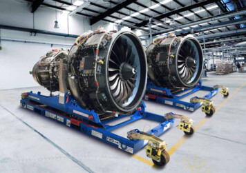
THE POWEROF FLIGHTCFM56-3 REGULATION1RXCF 04/02/2006
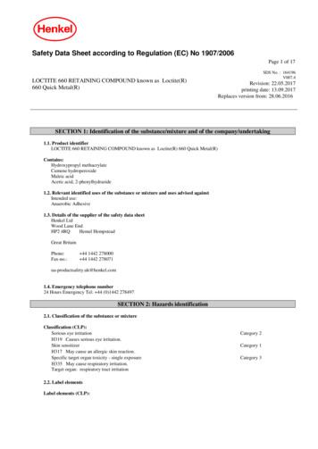
THE POWEROF FLIGHTCFM56 - 32RXCF 04/02/2006
Speed Governing SystemFuel Limiting SystemIdling SystemMain TasksVBVN1 Vs PVSVHPTCCVAdditional TasksMECN1 Vs ZN1 Vs TCorrectionsPMCCFM 56 - 3ENGINE OPERATIONAL CONTROL3RXCF 04/02/2006THE POWEROF FLIGHT
THE POWEROF FLIGHTENGINE OPERATIONALCONTROL The CFM56-3 engine control systemconsists of both:HYDRO MECHANICAL UNITELECTRONIC UNIT4RXCF 04/02/2006
THE POWEROF FLIGHTHYDRO MECHANICAL UNIT MEC Ì Main Engine ControlAutomatically schedules:– WF ( Fuel Flow ) N2– VBV ( Variable Bleed Valve )– VSV ( Variable Stator Vane )– HPTCCV ( High Pressure Turbine ClearanceControl Valve )5RXCF 04/02/2006
THE POWEROF FLIGHTELECTRONIC UNIT PMC Ì Power Management Control– Provide FAN schedulingN16RXCF 04/02/2006
CONTROL SYSTEM SCHEMATIC7RXCF 04/02/2006THE POWEROF FLIGHT
CONTROL SYSTEM SCHEMATICTHE POWEROF FLIGHT(Cont’d)N1ÖFan SpeedN2ÖCore SpeedWFÖFuel FlowTMCÖTorque Motor CurrentPS12ÖFan Inlet Static Air PressurePS3ÖCompressor Discharge PressureCBPÖCompressor Bleed PressureT12ÖFan Inlet Total Air TemperatureT2.5ÖHPC Inlet Air TemperatureT2ÖFan Inlet TemperatureTC1ÖTurbine Clearance Control 5Th StageTC2ÖTurbine Clearance Control 9Th StageTC3ÖTurbine Clearance Control Timer Signal8RXCF 04/02/2006
THE POWEROF FLIGHTENGINE STATIONS2512HP Compressor InletSecondary Flow Inlet32HP Compressor DischargePrimary Flow Inlet49. 5Stage 2 LPT Inlet9RXCF 04/02/2006
THE POWEROF FLIGHTMECOIL/ FUELHEATEXCHANGERMECFUEL PUMP10RXCF 04/02/2006
THE POWEROF FLIGHTMEC OPERATION MEC is an Hydro mechanical device using fuel pressure to work. A device monitors fuel pressure at low flow conditions for MECservo operation.FUEL PUMPBYPASSLP STAGEVALVEMEC Fuel Metering SystemFUELFUELFUEL PUMPMETERINGSHUT-OFFHP STAGEVALVEVALVEPRESSURISINGVALVE11RXCF 04/02/2006
THE POWEROF FLIGHTMEC PURPOSE The MEC’s job is divided in 2 tasks:MAIN TASKS:– Speed governing system– Fuel limiting system– Idling systemADDITIONAL TASKS:Control functions to optimise engine performance– VBV– VSV– HPTCCV12RXCF 04/02/2006
SPEED GOVERNING SYSTEMTHE POWEROF FLIGHTMECSPEEDGOVERNINGSYSTEMN2 demandPS12FMVT2N2 actualWfFuel13RXCF 04/02/2006
THE POWEROF FLIGHTFUEL LIMITING SYSTEM During transient operation, the speed governing system could changethe fuel flow beyond the safe limits. The purpose of the fuel limiting system is to define and impose correctengine fuel flow limits during rapid transients:ACCELERATIONSDECELERATIONSSTARTS14RXCF 04/02/2006
THE POWEROF FLIGHTFUEL LIMITING SYSTEM EMN2CBPSYSTEMN2 demandPS12 /T2N2 actualFMVWfFuel15RXCF 04/02/2006
THE POWEROF FLIGHTIDLING SYSTEMHIGH IDLE: Used only when anti-icing is selected or if a flying aircrafthas flaps configuration 15 . It is optimised to provide rapid recovery of takeoff thrust ifrequired.LOW IDLE: Ground idle:Provide adequate taxi thrust while minimisingnoise, fuel consumption and braking effort Flight idle:Scheduled to minimise fuel consumption.16RXCF 04/02/2006
THE POWEROF FLIGHTIDLING SYSTEM URATIONLIMITINGPLA IDLEYes / NOSYSTEMSETTINGN2CBPN2 demandPS12 /T2N2 actualFMVWfFuel17RXCF 04/02/2006
MEC ADDITIONAL TASKSTHE POWEROF FLIGHTVBV SYSTEM VBV system positions 12 valves byhydraulic pressure acting upon a fuel gearmotor. The fuel pressure is scheduled by theMEC. VBV feedback cable is positioned toprovide the MEC with a current VBVposition to compare with the desiredposition.18RXCF 04/02/2006
MEC ADDITIONAL TASKS (Cont’d)THE POWEROF FLIGHTVBV SYSTEM (Cont’d)19RXCF 04/02/2006
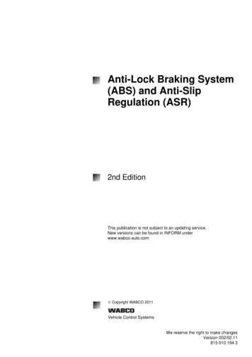
MEC ADDITIONAL TASKS (Cont’d)THE POWEROF FLIGHTVBV PURPOSEAs the Compressor is optimised for ratings close to maximum power engineoperation has to be protected during deceleration or at low speed:Without VBV installed:At Deceleration or Low speed Booster Outlet Airflow much more than Booster Pressure Ratio LPC stall margin reducedTo re-establish a suitable mass flow VBV are installed on the contour of the primaryairflow stream between booster and HPC to download booster exit.With VBV installed:At Deceleration or Low speed VBV fully open Booster Pressure Ratio but same Booster Outlet Airflow Plenty of LPC stall margin20RXCF 04/02/2006
MEC ADDITIONAL TASKS (Cont’d)THE POWEROF FLIGHTVBV PURPOSE (Cont’d)BOOSTERPRESSURERATIOTYPICAL LPC FLOW CHART1Acceleration Schedule5If VBV not closed3Deceleration Schedule4If VBV not open2Operating LineEfficiency MaxiEfficiencyDesign Point3MCTSTALLREGIONISO N1 Line24VBVOperation5IDLE1BOOSTER OUTLET AIRFLOW Low speed or DecelerationLOW EFFICIENCYREGION VBV OPEN High speed or acceleration VBV CLOSED21RXCF 04/02/2006
MEC ADDITIONAL TASKS (Cont’d)THE POWEROF FLIGHTVSV SYSTEMVSV system changes the angle of the HP Compressor IGV andN 1,2 and 3 stator stages according to the MEC computation.MEC directs a resulting high pressure fuel flow to the dual VSVactuators.The actuators mechanically position the VSV.A feedback cable provides the VSV position to the MEC.A comparison is performed between schedule requirements andactual VSV position to determine the need to continue actuatorcontrol or not.22RXCF 04/02/2006
MEC ADDITIONAL TASKS (Cont’d)THE POWEROF FLIGHTVSV SYSTEM (Cont’d)23RXCF 04/02/2006
MEC ADDITIONAL TASKS (Cont’d)THE POWEROF FLIGHTVSV SYSTEM (Cont’d)24RXCF 04/02/2006
MEC ADDITIONAL TASKS (Cont’d)THE POWEROF FLIGHTVSV PURPOSE The Compressor is optimised for ratings close to maximum power. Engine operation has to be protected during deceleration or at low speed. VSV system position HPC Stator Vanes to the appropriate angle of incidence.VSV (3)IGV- VSV optimise HPC efficiency.ROTOR- VSV improve stall margin fortransient engine operations.VSV 1Etc ROTORSTAGEIGV (Inlet Guide Vane)25RXCF 04/02/2006
MEC ADDITIONAL TASKS (Cont’d)THE POWEROF FLIGHTVSV PURPOSE (Cont’d)COMPRESSORPRESSURERATIOTYPICAL HPC FLOW CHART1Acceleration ScheduleEfficiency 2If VSV not openMaxiEfficiencyDesign Point3Deceleration Schedule4Operating Line21MCTSTALLREGIONISO N1 LineVSVOperation4 Low speed or Deceleration3IDLECOMPRESSOR OUTLET AIRFLOWLOW EFFICIENCYREGION VSV CLOSED High speed or acceleration VSV OPEN26RXCF 04/02/2006
CLEARANCE CONTROLTHE POWEROF FLIGHT Operating tip clearance in the core engine are of primaryimportance. They determine:Steady state efficiencies: Fuel consumptionTransient engine performance: Peak gas temperature Compressor stall margin27RXCF 04/02/2006
CLEARANCE CONTROL (Cont’d)THE POWEROF FLIGHT Clearance Control in the CFM56 engine is accomplished by a combination of3 mechanical designs:Passive control: Using materials in the compressor aft case with lowcoefficient of thermal expansion.Forced cooling: Using Low Pressure Booster discharge cooling air forcompressor and turbine.Automatic control: HPTCC VALVE and HPTCC TIMER are used to control thetip clearance between HPT blades and stationary tip shrouds.28RXCF 04/02/2006
HPTCCV ACTUATIONTHE POWEROF FLIGHT Automatic Control is using Bleed Air from 5Th and 9Th stages ofHPC to either cool or heat the HPT shroud.AIRFROM5ThSTAGEN2 95 %YES / NOMECHPTCC TIMERAIRCRAFTON THEGROUNDYES / NOHPTCCVALVEHPT SHROUDAIRFROM9ThSTAGE29RXCF 04/02/2006
HPTCCV ACTUATION (Cont’d)THE POWEROF FLIGHT During flight:- Air selection is determined by fuel pressure signals sent fromthe MEC to the TIMER.- The TIMER sends fuel pressure signals without change toactuate the HPTCC VALVE.- The selected bleed air is ducted to a manifold surrounding theHPT SHROUD.30RXCF 04/02/2006
HPTCCV ACTUATION (Cont’d)THE POWEROF FLIGHT During takeoff:- The TIMER overrides the normal MEC operation of the valve.- It is sequencing a transient air schedule over a specified time periodto maintain a more nearly constant HPT blade tip clearance duringthe period of HPT Rotor/Stator thermal stabilisation.- This maintain Turbine efficiency and decreases transient EGTovershoot.- A lockout valve permits the TIMER to actuate only once per enginecycle. ( i.e. from start to shut down)31RXCF 04/02/2006
HPTCCV ACTUATION (Cont’d)THE POWEROF FLIGHT32RXCF 04/02/2006
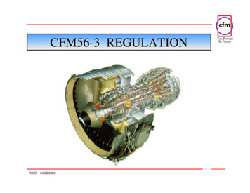
HPTCCV ACTUATION (Cont’d)THE POWEROF FLIGHT The TIMER SEQUENCE:- Starting Reference Point is when the engine reach 95 % N2.- Then:0 to 8 s No air8 to 152 s 5Th stage air152 to 182 s 5Th 9Th stage air33RXCF 04/02/2006
HPTCCV ACTUATION (Cont’d)NO TIMERTHE POWEROF FLIGHTTIMERSTATOR ØROTOR ØCLEARANCE with TIMERNo Air0s5Th stage Air8s5 9Th stage Air152 s182 sCLEARANCE without TIMER34RXCF 04/02/2006
PMCINPUT POWERTHE POWEROF FLIGHTCOCKPIT SW:Ö PMC On / OffPS12INPUT SIGNALS:Ö N1, T12, PLAOUTPUT SIGNALS:Ö FOR MEC TORQUE MOTORMONITOR CONNECTION35RXCF 04/02/2006
PMC PURPOSETHE POWEROF FLIGHT In a high bypass engine, total thrust is more accurately controlledby controlling N1 speed.FAN is 80% of the POWER !This is accomplished byvarying N2 speedto reach theaccurate N1 speed.36RXCF 04/02/2006
PMC OPERATIONTHE POWEROF FLIGHT The main goal of the PMC is to make pilot’s job morecomfortable. PMC is performing automatically 3 corrections:N1 Vs ALTITUDEN1 Vs PRESSUREN1 Vs TEMPERATURE37RXCF 04/02/2006
PMC OPERATION (Cont’d)THE POWEROF FLIGHTN1 Vs ALTITUDE As the altitude is increasing, if you want to keep a steady thrust%, you need to increase N1.PMC ONPMC increase N1N1 PLA remain unchanged.STEADYTHRUST %PMC OFFThe PILOT must increase N1 PLA change.Z38RXCF 04/02/2006
PMC OPERATION (Cont’d)THE POWEROF FLIGHTN1 Vs PRESSURE As the pressure is decreasing, if you want to keep a steady thrust %,you need to increase N1.N1PMC ONPMC increase N1STEADYTHRUST % PLA remain unchanged.PMC OFFThe PILOT must increase N1 PLA change.P39RXCF 04/02/2006
PMC OPERATION (Cont’d)N1 Vs TEMPERATUREN1 AtMAXTHRUSTTEGTTHE POWEROF FLIGHTCORNER POINTTEMPERATURETtakeoff, to get the max thrust (flatrated thrust) as temperature increases, N1and EGT must also increase. But mechanical limitations impose alimit which is a temperature called:“Corner Point” or “Flat RatedTemperature”.Beyond it:PMC ONPMC is limiting N1 and EGTPMC OFFThe PILOT must limit N1 and EGT40RXCF 04/02/2006
PMC OPERATION (Cont’d)THE POWEROF FLIGHT PMC efficiency start at 50% N1 and is fully efficient ator above 70% N1. PMC trims MEC to maintain the commanded thrust Schedule N1 is compared to actual N1.The error signalgenerates from the PMC an Output Current (TMC) to a torquemotor mounted on the MEC.The torque motor changes Fuel Flow (Wf).Ì N2 and N1 change.41RXCF 04/02/2006
PMC OPERATION (Cont’d)N1 / ZCORRECTIONN1 / PCORRECTIONTHE POWEROF FLIGHTN1 / RPMC on / offMECPLA42RXCF 04/02/2006
THE POWEROF FLIGHTTH EE NDTHANKS FOR YOURATTENTION !43RXCF 04/02/2006
Clearance Control in the CFM56 engine is accomplished by a combination of 3 mechanical designs: Passive control: Using materials in the compressor aft case with low coefficient of thermal expansion. Forced cooling: Using Low Pressure Booster discharge cooling air for compressor and turbine. Automatic control: HPTCC VALVE and HPTCC TIMER are used to control the tip clearance