Transcription
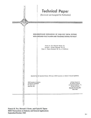
Francis K. Fox, Howard J. Grotts, and Clyde H. TiptonIEEE Transactions on Industry and General ApplicationsSeptember/October 1965E-1
Abstract - A method is described which has been used toreduce the difficulties encountered on several olddelta-ungrounded systems. Data are included which will helpin applying this to any particular power system. The schemegives an alarm whenever a ground fault occurs, permits everything to keep running even more assuredly than with an ungrounded system, and provides a method for quickly locatingthe fault. Circuit diagrams and photographs of actual equipment are included, and operating practice is summarized.IntroductionShould electric power systems be grounded and if so, whatis the best method to use? Much has been written, and manyheated arguments, not recorded, center about this subject. Before describing any one particular scheme, the authors will attempt to summarize the entire subject as objectively and asbriefly as possible.An ungrounded system is one in which no intentional connection is made between any part of the system and ground.Such a system is nevertheless grounded by the effect of thedistributed resistance and capacitance (mostly capacitance)which exists between all the conductors (cables, motors, transformers, etc.) and ground.A grounded system is one in which an intentional connection is made between the power system (preferably at theneutral junction) and ground, either directly or through an impedance.Present industrial power system practice seems to indicate a greater need for some form of system neutral grounding, as the voltage of the system increases. Many 480-volt systems have successfully operated ungrounded for years, but experience with the higher voltages has been such that almost all12-kV systems are grounded. Between these two voltages area great variety of grounding conditions: Most of the older2400-volt systems are ungrounded. Many 6900-volt systemsare still ungrounded. The best results in grounding 6900- and12 000-volt industrial systems have been obtained by grounding the neutral through a resistor to limit ground-fault currentto a desirable value, but retaining enough to produce selectivetripping of breakers. Some 4160-volt systems are solidly neutral grounded although, for industrial service, there is muchApproved by the Petroleum Industry Committee forpresentation at the IEEE Petroleum Industry TechnicalConf., Houston, Tex., September 13-15, 1965.Francis K. Fox is with the Central Electric Company, SanFrancisco, Calif.Howard J. Grotts is with the Tidewater Oil Company,Avon, Calif.Clyde H. Tipton is with the Standard Oil Company ofCalifornia, Richmond, Calif.Francis K. Fox, Howard J. Grotts, and Clyde H. TiptonIEEE Transactions on Industry and General ApplicationsSeptember/October 1965preference for resistance grounding at this, as wellas at other voltage levels above 600 volts. Powercompany practice is usually to ground the neutralsolidly, if available. Many 480-volt industrial systems have been solidly grounded. In the last fewyears, many 2400- and 4160-volt systems have beenresistance grounded with ground-fault immediatetripping of breakers or high-voltage motor controllers.What determines the best power system? Theideal system would be one in which a failure neveroccurred but, even if such a system could be built,the cost would be prohibitive. So power systems aredesigned to produce as little trouble as possible.The hooker is in defining the word “trouble.”First, there is the difficulty of obtaining the moneywith which to build the power system: no one canoverlook that trouble. Next, recollect all the troubleyou have experienced from power outages or equipment failures and what it cost you. You have read orheard about other engineers’ troubles; evaluate themas they might affect you if those same troubles appear in your plant.The next step is devising a system with featuresfor protecting against these troubles. However, thecost of the various protective features must alwaysbe balanced against the cost of the troubles.Electrical failures occur in many ways, but mostfailures originate as ground faults. In this paper, theauthors are confining themselves to a brief summaryof how system neutral grounding may affect thetrouble which such failures produce.For most industrial power systems 2400 voltsand above, probably the least trouble will be produced if the system neutral is grounded through aresistor which will limit ground-fault current to afew hundred amperes, but will retain enough current to trip a breaker immediately and remove thefaulty equipment from the system. This method ofgrounding has the following advantages:1) System overvoltages are reduced both in magnitude and duration.2) Faulty equipment is immediately known.3) Damage at the point of fault is negligible.4) Hardly any voltage disturbance is noticed onthe system, and no other loads are affected.5) Methods for detecting and removing groundfaults in modem switchgear with the use of breakers(not fuses) and high-voltage motor controllers areaccurate, sensitive, and economical.E-2
However, this method has several disadvantages:1) No warning precedes the tripping of a breaker or theopening of a motor contactor.2) Sudden stoppage of a motor, or of all loads on an entirecircuit, may cause considerable damage to a process plant.3) On an old system, adding needed neutral groundingequipment and ground-fault relaying is expensive.For various reasons, there are many ungrounded 2400- or4160-volt systems in operation. These systems are all subjectto the following possible troubles:1) Certain types of ground faults can produce dangeroushigh transient overvoltages throughout the entire system.2) These overvoltages can a) produce an immediate failure of some other equipment on another feeder resulting in thesimultaneous tripping of two breakers, or b) weaken other insulation so that the next failure will take place sooner.3) A ground fault sometimes goes unnoticed for days orweeks. Even if no dangerous transient overvoltages are produced, such a fault usually develops into a phase-to-phase faultFig. 1. Diagram of grounding method for system havingwith consequent increased damage at the point of fault.ungroundeddelta power supply of 24UO or 4,160 volts: con4) It is annoying, time consuming, and sometimes hazardous to locate the ground fault by switching loads on and off, in trol and protective circuits not shown.order to remove the faulty equipment from the system.fault, so that it can be traced to the point of fault. This pulsingHigh Resistance Grounding System Utilizing Pulsing is accomplished without ever removing the high-resistanceneutral grounding connection.Ground-Fault Detector Apparatus*6) Provide a means for measuring the system-chargingcurrent so that the proper degree of minimum neutral groundThis high-resistance grounding scheme was developed toing by high resistance can be accomplished.overcome the troubles which are associated with an ungroundedSystem-charging current is the highly leading power facsystem and which have already been described. Briefly, thetor ground-fault current (on an ungrounded system) requiredscheme is designed toto charge the capacitance of the other two phases to ground.1) Eliminate the high transient overvoltages which canThe component of ground-fault current controlled by theappear during arcing ground faults.high-resistance neutral ground must be slightly greater than2) Give immediate warning when a ground fault occurs.the system charging current. The reason for this, as well as a3) Accomplish this with a minimum of system neutralcomplete explanation of the nature and causes of system ovgrounding, so that the current at the ground fault will be onlyervoltages can be found in the General Electric Industrialslightly greater than (but perhaps even less than) the fault curPower Systems Data Book [1].rent would be if the system were left ungrounded. (In the caseof a sputtering fault, the ground-fault current in an ungroundedDescription of Systemsystem may be increased to several times the bolted-fault value.High-resistance grounding will hold the current value to subFigure 1. illustrates the manner in which grounding isstantially the steady-state bolted-fault value.)accomplished. The system neutral is derived by three small4 Enable the system to continue operation with a single(3- to 10-kVA) transformers, connected wye-broken delta, asline-to-ground fault present, in the same manner as an unshown. The primary neutral is grounded through a currentgrounded system. (The high-resistance grounding circuit is antransformer and ammeter, so that ground fault current can beexcellent damper of high-frequency transient oscillations someasured. The secondary neutral is connected to a resistorthat, in some cases, the ability to continue operation might bewith taps, so that the proper resistance can be used to controlenhanced.)the current which will flow into a ground fault. The small5) Provide a means for pulsing the current into the groundarrows show the path of the ground-fault current. Notice that*U. S. patent pending; applied for by F. K. Fox for the the ground-fault current is equally divided in the three smalltransformers, and that it also circulates through the delta supGeneral Electric Company.ply system. The arrows represent currents which are in phase.Francis K. Fox, Howard J. Grotts, and Clyde H. TiptonIEEE Transactions on Industry and General ApplicationsSeptember/October 1965E-3
Several actual ground faults have been located inthis manner. Several ground faults have also been deliberately placed on systems of different types in order to check the ability of the system to follow thesepulses to the point of fault.Corresponding currents in the secondary neutral circulate in the broken delta and through the resistor. This method is equivalent to losingOn systems involving bare overhead lines onthe delta and grounding the primary neutral through a high resistance.poles, tracing the signal is simple because all the faultFigure 2 presents the actual voltage conditions, both normally andcurrent is forced to return through ground. On syswith a ground fault on the system. A typical 2400-volt power systemtems involving conduit, tracing the signal is harderof around 5000 kVA may require 3 amperes, as shown, at the point ofbecause the fault current tends to return through thefault. This would produce 1 ampere in each primary and, if the transconduit of the circuit involved. To the extent that thisformer ratio is 20 to 1, a current of 20 amperes through the resistor athappens, the return current in the conduit cancels out208 volts. This allows using a low-voltage resistor and pulsing contactor.the fault current flowing out through the conductor toWith no ground fault on the system, the voltage at the broken deltathe point of fault. Fortunately, even on all conduitis zero. When a ground fault occurs, this voltage increases to a maxisystems, this cancelling effect is not 100 percent. Ifmum of 208 volts, so that the voltage relay VR can give the alarm.the hook-on ammeter is sensitive enough and if it isFor the typical system shown, this is equivalent to grounding theinsensitive to other local magnetic effects, the faultsystem neutral through a 460-ohm resistor. The voltage conditionscan be located. The return current divides into strangeshown are for a solid ground fault but, even for a high-resistance fault,unpredictable patterns and appears on conduits andenough voltage will appear across the resistor to operate the voltagemetal structures not associated with the faulty circuit.relay and sound an alarm. For example, if the entire ground-fault pathAlso, these structures very often carry current attribintroduced 1000 ohms of resistance, the voltage across the resistorutable to other causes not associated with the fault. Inwould be around 55 volts. Relay VR can be set to pick up at approxiany case, the definite rhythmic pulse of themately 16 volts, which would actually detect and give the alarm, evenground-fault current is extremely helpful.if the incipient ground fault had a resistance of approximate 4000 ohms.The signal receiver which has been found mostuseful in tracing the pulsing ground-fault current isthe hook-on ammeter shown in Figs. 3 and 4. ThisThe operator then initiates a control circuit which causes the pulsdevice has a split core with a window large enough toing contactor to close approximately 40 times per minute to produceencircle a 5-inch conduit. The handle is insulated fromcurrent pulses of about a half-second duration. These pulses can bethe core so that it can be used safely on power cablestraced to the point of fault, with the use of a hook-on ammeter, asof 2400- or 4160-volt systems which are not in conshown.Locating the FaultFrancis K. Fox, Howard J. Grotts, and Clyde H. TiptonIEEE Transactions on Industry and General ApplicationsSeptember/October 1965E-4
duit. Several degrees of sensitivity are provided. The split corecompletely encircles the conduit, or cables in air, thereby ignoring the effect of other local magnetic fields to a great extent.Physical EquipmentSeveral types of power systems have been grounded inthe manner described. One of the first installations is shownin Fig. 5. The power supply consists of a 3750-kVA 3-phase tion is entirely by bare overhead lines on poles. The ground2400-volt transformer. Various feeders to a large tank-farm ing equipment at this location is in four separate housingsarea originate in the switchgear in the background. Distribu- consisting of a fused oil switch, a 3-phase oil-immersedgrounding transformer, a relay and control panel, and a sec-Francis K. Fox, Howard J. Grotts, and Clyde H. TiptonIEEE Transactions on Industry and General ApplicationsSeptember/October 1965E-5
ondary resistor.At another location, the same scheme has been used except that a spare breaker in a switchgear line-up was substituted for the fused oil switch. This is a superior method but,of course, the breaker costs more than the fused switch.A total of five such installations are set on a resistor tap toproduce approximately 2.7 amperes into a ground fault, withpulsation to 3.5 amperes while hunting for the fault. The pulsing current will probably be increased to make ground-faulttracing easier.A more compact single-enclosure construction is shownin Figs. 6 and 7. This installation is on a 4160-volt systeminvolving steam turbine-generators having a total capacity of15 000-kVA and two 10 000-kVA transformer sources. Thefused disconnect switch and three dry-type grounding transformers are mounted in the left-hand high-voltage sectionwhich is padlocked closed. The low-voltage resistor, relaysand controls are all mounted in the right-hand section and arereadily accessible. Louvres are provided to ventilate the resistor, which must dissipate approximately 15kW when a solidground fault occurs on the system. Normally, the resistor carries no current. This 4160-volt system was found to have acharging current of approximately 6.4 amperes with a totalload of 20 000-kVA. The resistor is set on the tap to produce6.5 amperes into a ground fault. Pulsing to 9.0 amperes isutilized when hunting for the fault.Similar single-enclosure equipment is presented in Figs.8 and 9. This installation also involves 15 000-kVA of steamturbine-generation but, in this case, the neutral of each gen-Francis K. Fox, Howard J. Grotts, and Clyde H. TiptonIEEE Transactions on Industry and General ApplicationsSeptember/October 1965erator was readily available through three single-pole disconnects. Therefore, the grounding transformer had only tobe a single-phase unit shown at the lower right. Both thetransformer and resistor sections of this equipment meat havebolted covers. This 2400-volt system was found to have 3.6amperes charging current with a 13 000-kVA load. The resistor was set to produce 4.5 amperes into a ground fault,with pulsation to 8.0 amperes while tracking the signal tolocate the fault.Operating Experience At Richmond RefineryA pulsing ground-fault detector was installed on the2400-volt system at the Standard Oil Refinery, Richmond,Calif., in December 1963. Its primary function was to limitthe transient overvoltages, during a line-to-ground fault onthe system. Its secondary function was to impress a pulse onthe fault current so that a portable signal detector could beused to trace the pulse to the grounded conductor.The 2.4-kV system consists of three turbine-driven generators rated at 5000-kVA each, connected through reactorsE-6
to three separate 2.4-kV busses. Each bus is connectedthrough a a reactor to a common synchronizing bus.From the three busses, thirteen radial feeders distribute power to load centers throughout the refinery (Fig.10).Prior to installing the pulsing ground detector, theneutrals of the generators were connected through aresistor to ground. A 10/5-ampere current transformeron the grounded line was connected to a recordingammeter and an alarm panel. When the alarm sounded,it was the signal for a long tedious search for thegrounded conductor. First, each bus section with itsgenerator had to be separated from the grounding system to determine which bus section contained the fault.After this had been established, feeders were paralleled and loads switched from one bus to the other inorder to determine which feeder contained the groundfault. Next, the faulted feeder was paralleled andsectionalized until, finally, after several hours ofswitching and various manipulations, the location ofthe ground fault was narrowed down to a comparatively short section of line supplying perhaps five orTABLE Isix motors. The motors were then shut down, one at atime, until the fault cleared The entire operation, fromValues of Actual Tests on 2400-Volt Systemsstart to finish, many times required as many as eighthours.kVAThere have been two ground faults on the 2.4-kVTotalsystem since the pulsing ground detector was installed.Trans- (Motors*The first one occurred on August 7, 1964 about 3:30Motorsformers andCharging ChargingP.M. The operating crew had witnessed a demonstraRunning Connected TransCurrent Current,tion of the use of the Pulsator but this was the firstSystemhpkVAformers) Measured A/MVA“real thing.” It required only 28 minutes from the timethe alarm sounded to find and shut down the faultyTidewater submotor. The elapsed time could have been considerstation 12700 4142 6842 2.550.373ably less but, in this case, the fault happened to be onTidewater subthe No. 13 feeder, the last feeder to be checked, andstation 24500 3000 7500 1.980.264was located quite a distance from the power plant nearTidewater subthe end of the feeder.station 7A1900 1500 3400 0.420.124The second ground fault occurred at 6:00 A.M.,Tidewater subJanuary 4, 1965. The operating crew at the power plantstation 7B (1) 1900 1500 3400 0.290.085had not been on duty when the previous ground faultTidewater subdeveloped. Therefore, this was also a “first” for them.station 91225 1200 2425 0.340.140In 18 minutes, the fault was traced to a forced-draftRichmondfan motor on the No. 6 station service feeder.refineryThus far, the authors’ experience with the pulsing2400ground detector has been extremely satisfactory. Thevolt powertwo ground faults at the Richmond Standard Oil Replant11 525 11 925 23 450 3.60.154finery were located in minutes, rather than hours; itwas not necessary to shut down any motor-driven*Assuming 1 hp 1kVA for motors.(1) This substation feeds no 2300-volt motors smaller than 200 equipment while searching for the fault; and equallyhp, has only 675 feet of RL (5000 volts 3/C) cable total, 2 to 200 hp important, the hazard associated with hasty switchand 1 to 1500 hp motors were running, and 2 to 750 kVA (three 2300/ ing was avoided.440-volt) transformers were energized.Francis K. Fox, Howard J. Grotts, and Clyde H. TiptonIEEE Transactions on Industry and General ApplicationsSeptember/October 1965E-7
Operating Experience at Avon RefineryThe Tidewater Oil Company, Avon California Refinery, haseight 2400-volt 3-phase delta systems. Each system is independent of the others and is fed by its own 2400-volt substation. Each substation is located at a load center. Many of thesesystems are now provided with the high-resistance groundingscheme, with ground-fault alarms and the pulsing signal to fault,as described in this paper. A red alarm light is provided aboveeach substation and an annunciator alarm panel has been installed in the refinery electric shop. When a ground fault takesplace, both the substation alarm light and the electric-shop annunciator panel will light up. So far, this alarm system hasworked satisfactorily.Prior to the installation of this high-resistance groundingscheme, every time a “dreaded” ground fault arose, a great manyhours were required to isolate, locate, and repair the fault. Ona few occasions, the ground faults did not have to be trackeddown because the trouble was actually multiple simultaneousfailures.The first grounding system was placed in operation onOctober 24, 1962. The other grounding systems were installedin 1963. All the grounding systems have been in service forabout 1 1/2 years.Four ground faults have occurred on systems involvingopen-wire lines since these systems have been in operation.The first one appeared when a potential transformer on the2300-volt side of a 2300/440-volt 3-phase transformer bankwent to ground. This transformer bank is fed from an open-wireoverhead line by way of a pole riser from the main 2400-voltsubstation switchgear through lead-covered cable in conduitto the overhead line, then from the overhead line by way oflead-covered cable in conduit to the transformer. The pulsingcurrent was 3 and 3.8 amperes. The faulty circuit was readilyfound at the substation. It was then a matter of checking for thepulse current at each pole riser fed from the overhead-line circuit until the faulty riser and the trouble was found. All in all,the actual “tracking down” took an hour or two. The secondground fault occurred when the terminal box for a 2300-volt800-hp motor filled with rain water. This motor was also fedfrom an overhead line in much the same manner as was thecase with the first fault. Trouble 3 took place on the primaryside of a poIe-mounted series lighting transformer. Both faults2 and 3 were tracked down with little difficulty. Trouble 4, alsofound very quickly, was a ground fault in a current transformerin one of the switch houses.substation are 3 and 4 amperes. The fault was in thehigh-voltage terminal box of a lighting transformer. With theground current dividing between the two parallel feeders, witha resulting pulse current in each feeder of 1 1/2 and 2 amperes, and with much of the signal cancelled out by returncurrent on the conduit, it was not possible for company personnel to pick up the pulse with the nonhook-on-type signalreceiver used. By a method of elimination, the trouble wasnarrowed down and the pulse was picked up in the conduitfeeding the faulty transformer.System-Charging Current DataActual charging current seems to vary from one systemto another. An actual test must be made on each system sothat the lowest current tap of the resistor can be used. Thistest can most conveniently be made after the grounding system is installed; therefore, an estimated charging current mustbe ascertained at the time the equipment is purchased. Theestimated charging current should be on the “high side.” Theresistor tap must later be selected so that the ground currentis slightly above the actual measured charging current. For2400-volt systems having an operating load of 15 000-kVAand less, it has not been the authors’ experience to find a charging current over 4 amperes. The one 4-kV system testedshowed a charging current of 6.4 amperes with an operatingload of approximately 20 000 kVA.The following values have been derived from the testspresented in the table:1) Overhead open-wire lines apparently have very littleeffect on charging current unless they are many thousands offeet in length.2) VL or shielded cable appears to have the most effect(in the order of 0.4 A/1000 ft for 2400 volts and 0.7 A/1000 ftfor 4-kV systems).3) Non-shielded cables in conduit, transformers, and motors also have some effect, in the order of:Non-shielded cables.05 for 2400 V in Amps per 1000 ftIn conduit.08 for 4160 V in Amps per 1000 ftTransformers0.3 for 2400 V in Amps per 1000 Kva.05 for 4160 V in Amps per 1000 KvaMotors .05 to .10 for 2400 V Motors in Amps per 1000 HP.07 to .12 for 4000 V Motors in Amps per 1000 HP4) Aerial cable approximates the value of cable in conduct.A fault-tracking experience which proved more difficult5) It is very important to include values for surge capaciwas on an all-conduit lead-jacketed cable system with parallel tors connected to the motor terminals or at switchgear buses.feeders serving a crude unit. The pulse intensities used for thisFrancis K. Fox, Howard J. Grotts, and Clyde H. TiptonIEEE Transactions on Industry and General ApplicationsSeptember/October 1965E-8
This equipment will add about 0.75 amperes at 2400 volts or1.3 amperes at 4160 volts, for each set of surge capacitors used.6) The authors wish to point out that these values werederived from limited test data and, therefore, are only approximate. It should also be realized that capacitance values willvary considerably with the wide ranges of cable, wire, motor,and transformer sizes installed in the typical refinery.7) The authors have noted recent published test data [3]wherein system-charging current of several 2400-volt miningpower systems was found to be in the order of 1.0 A/MVA ofsystem capacity. This is much greater than the current foundon any systems with which the authors have worked and isprobably caused by the extensive use of lead-covered orshielded cables used in underground mining operations andalso by the extensive use of surge capacitors at the terminals oflarge 2300-volt motors.References(1) Industrial Power Systems Data Book. Schenectady, N.Y.: General Electric Company, Sec 0.220 and App. C.(2) D. L. Beeman, Power Systems Handbook. New York:McGraw Hill, 1955.(3) W. R. Duffy, “How the Anaconda Company protectsits system against ground faults,” Indus. Power Sys., March1964.(4) “Grounding of Industrial Power Systems,” AIEE Special Publ. 953 (Green Book), October 1956, editorially revised on September, 1960.Francis K. Fox, Howard J. Grotts, and Clyde H. TiptonIEEE Transactions on Industry and General ApplicationsSeptember/October 1965E-9
Francis K. Fox, Howard J. Grotts, and Clyde H. Tipton IEEE Transactions on Industry and General Applications September/October 1965 E-3 However, this method has several disadvantages: 1) No warning precedes the tripping of a breaker or the opening of a motor contactor. 2) Sudden stoppage of a motor, or of all loads on an entire