Transcription
www.labelingsystems.compressure sensitive labelingPage 1 of 39
Copyright 2003 Labeling Systems Inc.All rights are reserved including those of translation. This book and parts there of may not beproduced in any form, stored in any retrieval system, or transmitted in any form or meanswithout prior permission from Labeling Systems Inc. (LSI).The information contained herein is based on the experience and materials collected from publicinformation sources. LSI is not responsible for the accuracy of its contents or for any damagesthat may occur because of errors or omissions. LSI does not by publication of this documentensure to anyone the use of such data against liability of any kind, including infringement of anypatent. Publication of this data book does not constitute a recommendation of any patent orproprietary right that might be involved.www.labelingsystems.compressure sensitive labelingPage 2 of 39
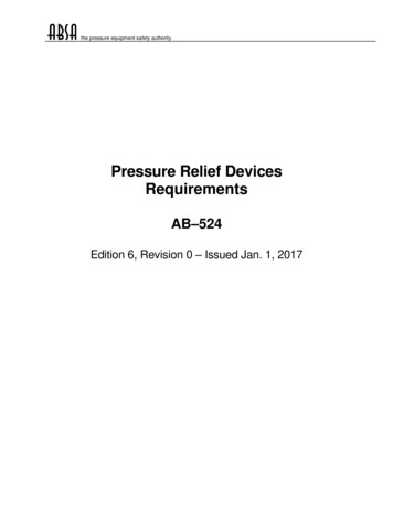
Pressure Sensitive Labeling1 Pressure Sensitive LabelsThe Pressure sensitive or PS labels we see on the products and cartons we use every day,every day consist of Face Stock and Adhesive. Depending on the adhesive used, they adhereto surfaces with moderate to light pressure. But the label we see is only part of the story. PSlabels are constructed as a sandwich of several layers: Top Coat Face Stock Adhesive Release Coat LinerLabel (Adhesive, Face Stock & Top Coat)Web (Liner & Release Coat)AdhesiveLinerFace StockRelease CoatTop CoatPressure Sensitive Label ConstructionLet’s build up from the bottom.1.1LinerThe liner is the backing paper that makes up the web of a roll of labels.1.2Release CoatThe release coat is a coating applied to the top surface if the liner. The release coat is designedto resist the adhesive, allowing the face stock and adhesive to peel away from the liner.www.labelingsystems.comPage 3 of 39
Pressure Sensitive Labeling1.3AdhesiveThe adhesive is the glue that sticks the face stock to the product. There are a wide variety ofadhesive formulations available. Adhesive selection is generally based on the application: Permanent or Removable Product Surface Material – Paper, Plastic, Metal, etc. Label Application Temperature Product Storage Temperature Product Surface Texture - Smooth or Rough Wet or Dry Environment1.4Face StockAlthough the most common face stock material is paper, many other materials are usedincluding plastic films, foils, fabrics and laminates.1.5Top CoatThe top coat is a coating or lamination applied over the face stock, to provide physicalprotection from abrasion or to enhance some other property of the label. Top coats can be usedto improve adhesion or legibility of secondary imprints, typically used for date or lot coding.Special UV sensitive varnishes or films can be used to assist with label on product detection,during the labeling process.www.labelingsystems.comPage 4 of 39
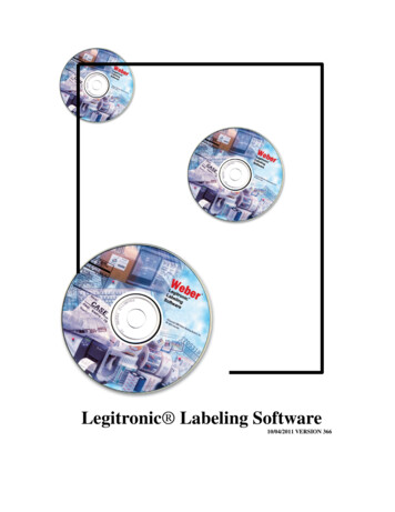
Pressure Sensitive Labeling1.6Label Copy PositionsThe orientation of the copy on a label is an important consideration when specifying andautomatic labeling system. The roll form and copy position chart below provides a standardizedway to describe the eight possible combinations. For automatic labeling applications, labels aretypically wound out.Roll Form Chart1.7Label SizeLabel size is defined based on the label’s orientation on the web as seen below.Label WidthWeb WidthLabel Feed (Length)www.labelingsystems.comPage 5 of 39
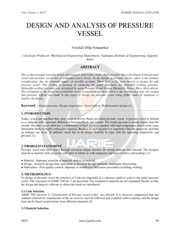
Pressure Sensitive Labeling1.8Web LengthA roll of labels consists of a sandwich of web and labels, rolled in a spiral around a core. Thechart below describes the length of the web on a roll of known diameter, based on the thicknessof the label/web sandwich.Web Length ChartO.D.(in)TOTAL THICKNESS OF COMPLETE CONSTRUCTION (MILS).0050.0055.0060 Econ.Litho Lam.Foil MAC tab60# Velvet60#.002Acetate.0065 Gloss60# Sat.004 Vinyl Metallics Cover100#TagRadianSat ingsystems.comPage 6 of 39
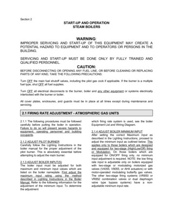
Pressure Sensitive Labeling2 Label ConvertingThe manufacture of pressure sensitive labels or label converting is a multi-step process. Insome cases, all of the steps described below can be completed on a single production line.Other label converters may choose to split the process into two parts; printing and finishing.Label converting consists of: Unwind Web Guide Printing Laminating Die Cutting Matrix Removal Web Splicing Slitting Inspection RewindLaminate UnwindColor 3Matrix RewindColor 2Color 1Die CuttingInspectionUnwindSlittingRewindPressure Sensitive Label Converting Process2.1UnwindLabel stock is unwound from a master roll and fed into the press.2.2Web GuidesWeb guides steer the web through the press to control print registration side to side. The webguides also control dimensional tolerances for the label and the liner.www.labelingsystems.comPage 7 of 39
Pressure Sensitive Labeling2.3PrintingOne of the most common methods for printing pressure sensitive labels is flexography. On aflexo press, a flexible plate, imprinted with a negative of the image to be printed, is wrappedaround a cylinder. Ink is transferred to the face of the plate. The web is rolled over the plate,transferring the image to the face stock. A flexo press includes one station for each color usedin the label.2.4LaminatingOn labels that include a laminated top coat, the surface layer is adhered to the face stock afterprinting.2.5Die CuttingA label cutting die is very similar to a flexo printing plate, but rather than a raised image, the diesurface is imbedded with “cookie cutter” like knives, designed to cut the face stock into theshape of a label. Under precisely controlled pressure, the web is rolled over the die. Set up ofthe die station is critical. The die must cut all the way through the face stock without cutting intothe liner. Problems with too deep or too shallow cuts will be described later.2.6Matrix RemovalDuring matrix removal, the matrix, the face stock material between the labels, is peeled from theliner and collected on a waste rewind roller.2.7SlittingTo improve production efficiency and throughput, labels are typically printed four up or six up,that is four to six labels are printed across the face of the web. At the slitting station, the web isslit into four or six separate rolls of labels. Precise, web guiding in the slitting station ensuresthat the edges of the web are straight and parallel and that the label location on the web isconsistent throughout the roll.2.8InspectionUsing a strobe light, the images on the web are inspected using a vision system or a humaninspector. Flags, little labels similar to “Post-it” notes, are attached to the web a the location ofany defect. The flags are attached at the edge of the web, so the stick out of the roll. In aseparate process, the roll is unwound and the defects are cut out. The roll is then spliced andrewound.2.9RewindThe most important factor at the rewind station is tension. If the roll is wound too tight, theadhesive may bleed. If the roll is too loose, it will be hard to handle and may telescope, whencarried horizontally.www.labelingsystems.comPage 8 of 39
Pressure Sensitive Labeling3 Introduction to Pressure Sensitive LabelersPressure Sensitive labelers came into existence during the 1950’s. Since their initialintroduction, the use of labelers has grown into two basic application typesApply Only – Use of Pre-printed labels in an automatic machine. There can be severalpurposes of this labeling including:3.1 Primary Decoration of the packagePromotional Labeling – many times may include the use of coupon type label stockSecurity Seal – also known as tamper evidentTheft Security – uses labels such as Sensormatic or Checkpoint Product Display – such as hang tabsPrint & Apply – the printing of labels is done by the labeler. This can either be done in a3.2“next label out” configuration or with labels in que prior to being applied (ex. loose loop).This type is usually associated with bar coding. There can be several purposes for thistype: Package Identification/Tracking – usually associated with shipping orwarehouse/distributionVariable Printed Information – such as ingredients of a product or nutritional information.Label Inventory Reduction – enables customer to reduce their inventory of pre-printedlabels.Primary Decoration - is becoming a more viable application with faster machines andgreater print resolutions becoming available or for labeling provided by 2nd tier suppliers.Print and Apply is the fastest growing sector of pressure sensitive labeling. Thermal andThermal transfer printing is accomplished using printers supplied by third partymanufacturers. Many web sites offer detailed information and background on thistechnology. SATO and Zebra for example offers these documents located at :http://www.satoamerica.com/bcpsg belingsystems.comPage 9 of 39
Pressure Sensitive Labeling4 Labeler CategoriesEither of the application types can be matched to the following labeler categories:4.1Stand Alone Labeler- uses a labeler with a product handling system that is eitherexisting or being provided by others. It may include a portable head mount (ex. T-basestand) or be installed directly on to a conveyor or other machine. This type of machine isalso referred to as a “label applicator”.AdvantagesUsually the most price effective solutionTypically takes up less floor spaceEasiest to installVery FlexibleDisadvantagesDoes not maintain product controlWill only guarantee label delivery accuracynot application accuracyChangeover may take longerA Stand Alone Labelerwww.labelingsystems.comPage 10 of 39
Pressure Sensitive Labeling4.2Product Handling System – combines the labeling head to be fully integrated to theproduct handling. These machines are also known as “Turnkey Systems”, “Open FrameSystems”, “Main Frame Systems”, or “Cabinet Based Systems”.Open Frame Top Labeling SystemA labeling system can either be used in an “in-line mode of operation” where products areautomatically fed into the machine or “off line mode of operation” where products aremanually placed onto and/or removed from the machine.AdvantagesSingle source responsibility for label and product controlGuarantees label on product placement accuracyGuarantees product throughput capabilityEasier change overDisadvantagesTypically more expensive than stand aloneTakes up more floor spacewww.labelingsystems.comPage 11 of 39
Pressure Sensitive Labeling4.3Semi-Automatic – is a machine where an operator manually places a product into afixture or jig assembly. The label is automatically applied by use of a operator controlledfoot pedal or photo-electric sensor located in the fixture.AdvantagesFaster and more accurate than hand labelingGuarantees label on product placement accuracyCost effective alternative to the Labeling SystemSingle source responsibility for label and product controlMachine is very portableDisadvantagesSlower throughput than fully automaticA Semiautomatic Bottle Wrap-Around Labeler5Selecting an Apply Only Stand Alone LabelerAny labeler, regardless of how simple or complex consists of the following components: Labeling Head Label Applicator Product Sensor Head Mountingwww.labelingsystems.comPage 12 of 39
Pressure Sensitive Labeling5.1Labeling HeadThe base component required for automatic label applications. The labeling head serves as theplatform for the unwinding and rewinding of the label material. The label applicator is installedon the head. In most cases the labeling head also houses the controls of the machine.Labeling head(s) are used in semi-automatic and fully automatic labeling systems. Othernames for label applicators are:Automatic LabelerLabeling ApplicatorLabelerHeadThis term may sometimes be used to refer to the application device on a labeler, i.e. tamp labelapplicator.5.1.1 Head OrientationLabeling heads can be supplied in either left or right hand version. Right hand machines feedlabel stock from left to right (viewing the machine from the front). A left hand machine feedsfrom right to the left.5.2Components of a Labeling HeadA labeling head is comprised of several major subassemblies. Unwind Assembly Web Drive Peeler Bar Label Sensor Rewind Assembly Controlswww.labelingsystems.comPage 13 of 39
Pressure Sensitive Labeling5.3Unwind AssemblyThis is the section of the labeling head where the label supply roll is mounted. This maysometimes be referred to as:Label Supply RollUnwind MandrelUnwind SupplyIn most labeling applications, labels are pulled from the unwind reel by the web drive assembly.A dancer arm is used to control a brake on the unwind reel. The brake stops the reel fromspinning when the web drive stops pulling.5.3.1 Roll SizeThis term is used to specify the outside diameter of the label roll and the inside diameter of theroll core. A typical labeling head allows a maximum roll size of 12” (304.8mm) O.D., wound ona 3” (76.2mm) I.D. core. Larger size rolls are also available.12” UnwindDancer Arm5.3.2 Powered UnwindFor high speed applications and for systems with large diameter label rolls, a separatelypowered unwind assembly may be utilized. The powered unwind assembly reduces the load onthe web and drive system, improves label stop accuracy and minimizing web breakage.www.labelingsystems.comPage 14 of 39
Pressure Sensitive LabelingPowered Unwind Drive and Nip Rollers (shown inhorizontal configuration on a print & apply head)5.4Powered Unwind Drive and Nip Rollers(shown in vertical dual unwindconfiguration)Web DriveThis refers to the roller assembly that pulls or pushes the web through the labeling head. Thedrive roller is always paired with a “nip” roller to insure the web stays fully engaged. Othernames are:Label Nip DriveNip Drive RollersNip Drivewww.labelingsystems.comPage 15 of 39
Pressure Sensitive LabelingNip RollerDrive Roller5.4.1Web Drive PackagesThere are 3 basic web drive packages for apply only machines. These drive packages connectto the external drive roller that pulls the web through the machine5.4.1.1 Clutch/Brake DriveThis incorporates an AC or DC motor running continuously. A heavy duty clutch is used toengage the drive roller and a heavy duty brake is used to stop the drive roller. Typical linear ratefor this is 0”/min to 1000”/min. The clutch and brake are wear components.5.4.1.2 Stepper Motor DriveA stepper motor is used on a labeling head which drives the label web through the machine.Stepper motors do not have wearable drive components which lets them maintain label stopaccuracy throughout the life of the machine.Some types of high position/accuracy stepper drives can have an encoder included to allow forthe motor to adjust for speed changes to the product or product handling system. This is anopen loop system and is sometimes called following mode.www.labelingsystems.comPage 16 of 39
Pressure Sensitive Labeling5.4.1.3 Servo Motor DriveSimilar to a stepper motor drive, a servo motor drive uses an encoder on the transport systemand an encoder on the motor. The pulses are matched to synchronize the motor to the transportsystem. Typically used for high speed and/or high accuracy applications, the advantage of thisdrive is that it is a "closed loop" drive. This means that speed variation feedback (via theencoder) is provided back to the Servo controller for it to automatically compensate forvariances in speed to the product or product handling to which the encoder is attached. In aclosed loop drive the feedback is more precise thereby creating greater labeling accuracy.5.4.2Speed EncoderAn encoder may be used in applications where either the web or product speed will vary. Theencoder tracks this variation in speed and translates the information into a train of electronicpulses. Each pulse equals a pre-determined amount of travel. In the example below each pulserepresents 1”.As an encoder goes faster the pulses increase causing the motor to increase speed. As theencoder goes slower, pulses decrease causing the motor to go slower.This in turn is fed back to the motor control package for the labeling head speed to be recalculated.The encoder is typically directly mounted to a drive shaft or can have a roller wheel that wouldrest on the conveyor or web. The wheel type installation is less accurate because it is prone toslippage.5.5Peeler BarThe peeler bar is used to separate the labels from the backing web or liner. As the label is beingseparated from the liner it is either being transferred directly onto the product surface or onto alabel applicator.www.labelingsystems.comPage 17 of 39
Pressure Sensitive Labeling5.6Air AssistApplication methods using a vacuum pad or grid where the label is completely transferred fromthe web require air assist. The pad or grid is offset slightly from the peeler bar. This relationshipcauses the trailing edge of the label to break cleanly from the web backing. As the label is beingpeeled from the web it is deflected away from the applicator surface. Air is used to “push” thelabel back towards the applicator grid so the vacuum source can hold the label once it is fullydispensed.5.7Label SensingFor many labelers, the peeler bar also serves as the platform for the installation of the labelsensor. The label sensor is installed as close to the peeling point as possible. This is calledPeeling Tip Label Sensing. The advantage to locating the sensor at the peel point is that thelabel being sensed is being applied. This removes label converting variables thus providing thebest label stop. It will also automatically advance to the next label should a label be missingfrom the web. On machines where the label sensor is located further back, a missing label(s)will cause a product to go unlabeled and a product to be double labeled.Machines equipped with a peeler extension typically do not have peeling tip sensing.Peeling Tip Sensingwww.labelingsystems.comPage 18 of 39
Pressure Sensitive Labeling5.7.1 Label Sensing (for machines equipped with Peeler Extensions)The label sensor is a "U" shaped sensor that consists ofa photocell and a light source. It is adjustable by slidingit on a mounting bar. It is a coarse adjustment andshould not be used for changing label stop orchangeovers. Fine adjustment should be made with thelabel stop pot on the circuit board.5.7.2Photo-Electric Label Sensor (Label PhotoCell/ Light Source)The label photo-cell is used to detect the gap or printedbar located between labels by reading the contrastbetween the label and backing. The signal from thephoto-cell is used to stop the label feed so that the labelstops in the correct position. The photo-cell is mountedin the block located above the Peeler Bar.The light source emits a light which is received by thephoto-cell. The assembly is mounted under the PeelerBar.The label sensitivity potentiometer controls the amount oflight that is emitted by the light source.5.7.3Label Photo CellClear Label Sensing (Capacitive Type)This type of sensor is used for labels that visually haveno distinguishable leading or training edge (such as aclear label) or if there is no registration mark on the lineror backing web. The sensor works by measuring thecapacitance between the sensor and the peeler bar (orany grounded surface). When the label web is passedunder the sensor, the capacitance between the sensorand the peeler bar is affected by the amount of materialpresent. The sensor can distinguish the differencebetween a label and the gap between labels. Acapacitive label sensor can typically detect the edge of alabel within 1/64” of an inch. The sensitivity is controlledby a potentiometer directly on the body of the sensor.Some types of sensors may not be compatible withmetallic inks printed on the label material.www.labelingsystems.comClear Label SensorPage 19 of 39
Pressure Sensitive Labeling5.8Rewind AssemblyIn most labeling heads, the rewind drive is slaved by atiming belt or chain from the web drive motor. A slipclutch is used to maintain a constant tension on the webso as to insure the web does not break as it is beingtaken up. Many times a web release device is includedon the rewind hub such as the “candy cane” typefeatured here.Rewind “candy cane”5.8.1Powered Type RewindFor systems designed for large diameter label rolls andwide webs a separately driven rewind assembly may beused. This eliminates rewind load on the web driveincreasing label stop accuracy. This driven rewindincluded a quick web release feature to easily removethe spent backing roll of waste.Quick Web Release5.9Apply Only Labeling Head ControlsEvery labeling head includes a control package that manages web advance and applicatorfunctions. The control package can be mounted in the labeling head or in a remote enclosure.Most control packages allow the user to adjust several important labeler control parameters,including:1. System Power – Controls power to motors, system controls and auxiliary devices.2. Label Jog – Pressing the “Jog” button advances the web by one label, without triggeringthe applicator. This function is typically used during system set-up, product change overand after a roll change.3. Label Sensitivity – Adjusts the gain of the label sensor. Proper gain adjustment allowsthe label sensor to consistently sense the transition from label to liner, as the web movesforward. Label Sensitivity controls can be located on the labeling head control panel oron the label sensor itself.4. Web Speed – On many labelers, the speed of the label web is adjustable. Labelingspeed is typically expressed in Inches per Minute (IPM).www.labelingsystems.comPage 20 of 39
Pressure Sensitive Labeling5. Product Delay – This is the delay between sensing the leading (or trailing) edge of aproduct and the beginning of the labeler’s apply cycle. Product Delay is typicallymeasured in time. However, labeling systems that include an encoder on the producthandling system can use counts from the encoder, to measure product delay. On timebased systems, Product Delay must be adjusted either automatically or manually eachtime the product handling system speed is changed. On encoder based systems,product delay remains constant regardless of conveyor speed.6. Label Stop - Label Stop adjusts the delay between sensing the edge of a label andstopping the web. Label stop can be measured in time or in stepper or encoder counts.If Label Stop is measured in time, it must be adjusted either manually or automatically,each time the web speed is changed. On stepper motor driven labelers or on servodriven labelers with integral encoders, Label Stop can be measured in stepper orencoder counts. In these applications, Label Stop remains constant regardless of webspeed.7. Applicator Time – Applicator Time adjusts the amount of time the applicator is actuated,i.e. for a tamp applicator, the amount of time a tamp pad is extended or for a blow-onapplicator, the amount of time the air jet is energized.Depending on the labeler manufacturer and model, labeler control parameters can be adjustedthrough dip switches and potentiometers or through digital Human Machine Interfaces (HMIs),with digital displays and keypads.Dip SwitchesPotentiometersHMI6 Selecting a Print & Apply Stand Alone LabelerComponents of a print & apply labeling head. Print Engine Unwind Assemblywww.labelingsystems.comPage 21 of 39
Pressure Sensitive Labeling 6.1Rewind AssemblyControlsPrint EngineThe print engine is the core of the print &apply labeling head. It provides the webdrive, label printing, dispensing of the label.The print engine is a third party component.Major print engine manufacturers includeSato, Zebra and Datamax.6.2Unwind AssemblyThis device is used to hold the unprinted roll of labels. On a print & apply labeling head, many ofthe web handling issues are managed by the print engine. The print engine controls the labelfeeding and provides the force required to pull the web through the printer at a constant speed.In the majority of applications, this force is also used to pull the web from the unwind reel. Adancer arm is used to control a brake on the unwind reel. The brake stops the reel fromspinning when the print engine stops pulling.For systems with large diameter label rolls, a separately powered unwind assembly may beincorporated into some designs. The powered unwind assembly reduces the load on the printengine improving label stop accuracy and print engine wear. The reduced load on the printengine also ensures consistent web speed across the print head and therefore consistent printquality.www.labelingsystems.comPage 22 of 39
Pressure Sensitive LabelingA separately poweredunwind is used for largediameter rolls.6.3Rewind AssemblyAll print & apply labeling heads utilize a separately driven rewind assembly to take up the spentbacking web.6.4Labeling Head ControlsIn a print and apply head, the control features are divided between the print engine and thelabeling head.The print engine manages the printing functions:1. Print Speed – an adjustable setting determined by application rate, label material, printmethod (direct thermal v. thermal transfer), and desired print quality. Typically the slowerthe print speed setting, the longer the life of the thermal print head and the better thequality of the print.2. Heat Control- the setting that controls temperature of the print head. The print head heatshould be as low as possible to maintain the desired print quality and minimize the wearfactor.3. Label Out/ Low Ribbon/Ribbon Out – monitors these mediums required for label printing.These functions may be tied into a separate alarm package such as a beacon to providea visual warning.The print engine controls typically interface with label creation software. This is third partysoftware used to create the visual image and layout of the label.The print & apply labeling head control package performs the following functions:Power to the Machine to control the labeling head motor(s) and power to an auxillary devices(such as a hot stamp).Label Jog- used to advance without activating the applicator. This is typically used during set-upor changeover.www.labelingsystems.comPage 23 of 39
Pressure Sensitive LabelingLabel/Web Advance Functions1. Air Assist – is required for applications that use a transfer method on to a pad or grid (ex.tamp pad or blow-on). The air assist stays on for the full time that the label is feeding.Further details in applicator section.2. Applicator Time – used to control the amount of time the applicator solenoid stays on.This feature is required for most applications that use a transfer method onto a pad orgrid (ex. tamp pad or blow-on). Example: this feature controls the length of time an aircylinder stays extended during the application sequence. Further details in applicatorsection.3. Product Delay- used to control the start of the applicator sequence. By use of this delaytimer, the label position on the product can be changed in the direction of product travel.7 Print & Apply v. Apply & PrintOn machines with thermal printers, there are two methods to set up the applicator. Apply &Print is when the product sensor is triggered, the applicator can apply the label and then feedthe next label into the ready position on the tamp pad or vacuum grid. Print & Apply is whenthe product sensor is triggered, the labeler will print a label, feed it onto the vacuum grid or tamppad, and apply the label. Sometimes one sensor is used to print the label and an additionalsensor is used to trigger the machine to apply the label. This method allows for accurateplacement of the label and a positive control of the application process.8 Label Applicator TypesThe applicator is responsible for the delivery of the label to the product. The following are thegeneral categories of an applicator: Wipe-on / Roll-on - can use a brush, roller, or other material to wipe the label down.Vacuum Grid Wipe-on / Roll-on - label is peeled on to a spring loaded vacuum gridand either rolled or wiped on to the product.Blow-on – Uses a quick blast of air to apply the label to the product surfaceAir Cylinder Tamp- Uses an air cylinder and vacuum pad combination to apply the labelon to the product surface.Air Cylinder Wipe-on / Roll-on – is a hybrid of the Vacuum Grid Wipe-on / Roll-on andthe Air Cylinder Tamp.Custom – a unique design to fit the specific product, product handling system, or othercustom requirement.www.labelingsystems.comPage 24 of 39
Pressure Sensitive Labeling8.1Synchronous Type - can use a brush, roller, or other material. Also referred to as”merge type”Roll-onThis method is the oldest and most basicmethod of applying labels. It does exactlywhat it says, it rolls on the label as the labelis being dispensed onto a moving product. Itis capable of high speeds with goodaccuracy. The roller, usually made of foamor rubber, is usually spring loaded andmounted just ahead of the peeler bar. Thelimitations of the roll-on applicator are thatthe label must feed in the direction of producttravel and must match the speed of theproduct.Wipe-on/Brush-onThis method utilizes the same principles ofthe roll-on applicator with the exception thata brush or wipe assembly replaces the roller.This type is usually selected with productsthat
automatic labeling system. The roll form and copy position chart below provides a standardized way to describe the eight possible combinations. For automatic labeling applications, labels are typically wound out. Roll Form Chart 1.7 Label Size Label size is defined based on the label's orientation on the web as seen below. Label Feed (Length)