Transcription
Appears in the Proceedings of the 25th Annual International Symposium on Computer Architecture.Exploiting Fine–Grain Thread LevelParallelism on the MIT Multi-ALU ProcessorStephen W. Keckler, William J. Dally, Daniel Maskit, Nicholas P. Carter, Andrew Chang, Whay S. Lee Computer Systems Laboratory Artificial Intelligence LaboratoryStanford UniversityMassachusetts Institute of TechnologyGates CS Building545 Technology SquareStanford, CA 94305Cambridge, MA 02139skeckler, billd, danielm, achang, npcarter, wslee @cva.stanford.eduThis paper describes and evaluates the hardware mechanismsimplemented in the MIT Multi-ALU Processor (MAP chip) forextracting fine–thread parallelism. Fine–threads close the parallelism gap between the single instruction granularity of ILP andthe thousand instruction granularity of coarse threads by extracting parallelism with a granularity of 50-1000 instructions. Thisparallelism is orthogonal and complementary to coarse-thread parallelism and ILP. Programs can be accelerated using coarse threadsto extract parallelism from outer loops and large co-routines, fine–threads to extract parallelism from inner loops and small sub–computations, and ILP to extract parallelism from subexpressions.As they extract parallelism from different portions of a program,coarse–threads, fine–threads, and ILP work synergistically to provide multiplicative speedup.These three modes are also well matched to the architectureof modern multiprocessors. ILP is well suited to extracting parallelism across the execution units of a single processor. Fine–threads are appropriate for execution across multiple processors ata single node of a parallel computer where the interaction latenciesare on the order of a few cycles. Coarse-threads are appropriate forexecution on different nodes of a multiprocessor where interactionlatencies are inherently 100s of cycles.Low overhead mechanisms for communication and synchronization are required to exploit fine–grain thread level parallelism.The cost to initiate a task, pass it arguments, synchronize withits completion, and return results must be small compared to thework accomplished by the task. Such inter-thread interaction requires 100s of cycles ( 1 ! s) on conventional multiprocessors,and 1000s of cycles ( 10 ! s) on multicomputers. Because ofthese high overheads, most parallel applications use only coarsethreads, with many thousands of instructions between interactions.The Multi-ALU Processor (MAP) chip provides three on-chipprocessors and methods for quickly communicating and synchronizing among them. A thread executing on one processor candirectly write to a register on another processor. Threads synchronize by blocking on a register that is the target of a remote writeor by executing a fast barrier instruction.Microbenchmark studies show that with these register-basedmechanisms, a thread can be created in 11 cycles, and individualcommunication and synchronization actions can be performed in1 cycle. Communication is 10 times faster and synchronizationis 60 times faster than their corresponding memory mechanismsMuch of the improvement in computer performance over the lasttwenty years has come from faster transistors and architecturaladvances that increase parallelism. Historically, parallelism hasbeen exploited either at the instruction level with a grain-size ofa single instruction or by partitioning applications into coarsethreads with grain-sizes of thousands of instructions. Fine–grainthreads fill the parallelism gap between these extremes by enablingtasks with run lengths as small as 20 cycles. As this fine–grain parallelism is orthogonal to ILP and coarse threads, it complementsboth methods and provides an opportunity for greater speedup.This paper describes the efficient communication and synchronization mechanisms implemented in the Multi-ALU Processor(MAP) chip, including a thread creation instruction, register communication, and a hardware barrier. These register-based mechanisms provide 10 times faster communication and 60 times fastersynchronization than mechanisms that operate via a shared onchip cache. With a three-processor implementation of the MAP,fine–grain speedups of 1.2–2.1 are demonstrated on a suite ofapplications. Modern computer systems extract parallelism from problems attwo extremes of granularity: instruction-level parallelism (ILP)and coarse-thread parallelism. VLIW and superscalar processorsexploit ILP with a grain size of a single instruction, while multiprocessors extract parallelism from coarse threads with a granularityof many thousands of instructions.The parallelism available at these two extremes is limited. TheILP in applications is restricted by control flow and data dependencies [17], and the hardware in superscalar designs is not scalable.Both the instruction scheduling logic and the register file of asuperscalar grow quadratically as the number of execution unitsis increased. For multicomputers, there is limited coarse threadparallelism at small problem sizes and in many applications.The research described in this paper was supported by the Defense Advanced Research Projects Agency and monitored by the Air Force Electronic Systems Divisionunder contract F19628-92-C-0045.1
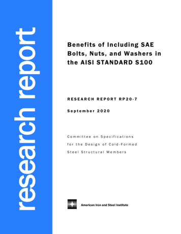
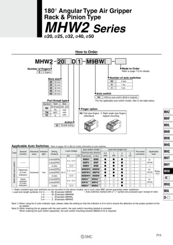
Figure 1 shows a block diagram of the MAP chip containingthree execution clusters, a unified cache which is divided into twobanks, an external memory interface, and a communication subsystem consisting of network interfaces and a router. Two crossbarswitches interconnect these components. Clusters make memoryrequests to the appropriate bank of the interleaved cache over the142-bit wide (51 address bits, 66 data bits, 25 control bits) 3 4 2Memory Switch. The 88-bit wide (66 data bits, 22 control bits)7 4 3 Cluster Switch is used for inter-cluster communication and toreturn data from the memory system. Each cluster may transmit onthe Memory Switch and receive on the Cluster Switch one requestper cycle. An on-chip network interface and two-dimensionalrouter allow a message to be transmitted from a cluster’s register file into the network. Multiple MAP chips can be connecteddirectly together in a two-dimensional mesh to construct an MMachine multicomputer. This paper focuses on the parallelismthat can be exploited within a single MAP chip. Future studieswill analyze application performance on the M-Machine.ExternalMemoryMemory Interface BusCacheBank 0MemoryInterfaceCacheBank 1TLBMemory SwitchCluster SwitchCluster 0Cluster 1NetworkOutputMAP chipI/O BusCluster 2(5*-,7698:' ;: 1 ?A@B.0C D ' E D FEach of the three MAP clusters isa 64-bit, three-issue, pipelined processor consisting of two integerALUs, a floating–point ALU, associated register files, and a 4KBinstruction cache1. Each integer register file has 14 registers perthread, while the floating–point register file has 15 registers perthread. Each thread also has 16 condition code (CC) registers tohold boolean values. Writes to a subset of the condition code registers are broadcast to the remote clusters. One of the integer ALUsin each cluster serves as the interface to the memory system. EachMAP instruction contains 1, 2, or 3 operations. All operationsin a single instruction issue together but may complete out of order. No hardware branch prediction is performed on the MAP, andbranches have three delay slots, due to the three pipeline stagesbefore execution. However, since all operations may be conditionally executed based on the one-bit value of a condition coderegister, many branches can be eliminated. In addition, branchdelay slots can be filled with operations from both sides of thebranch as well as with operations from above the branch.The execution units are 5-way multithreaded with the registerfiles and pipeline registers of the top stages of the pipeline replicated. A synchronization pipeline stage holds instructions fromeach thread until they are ready to issue and decides on a cycleby-cycle basis which thread will use the execution unit. Whilethis enables fast, zero-overhead interleaving on each cluster, theremainder of this paper uses only one thread per cluster.NetworkInputRouterNetworkFigure 1: Block diagram of the MAP chip, containing 3 clusters(processors) connected to the memory system and each other viathe Memory and Cluster switches.that use the on-chip cache. The MAP’s integrated mechanismsare orders of magnitude faster than those that operate via globalmemory. A study using several parallel applications shows thatthese mechanisms allow speedups of up to 2.1 using 3 on-chipprocessors when exploiting parallelism with a granularity of 80–200 cycles. If the register communication provided by the MAPis replaced with memory operations, fine–grain threads yield substantially less speedup, and sometimes slowdown.The next section describes the architecture and implementationof the MAP chip and details its mechanisms that support fine–grainthreads. The raw performance of these mechanisms is evaluated inSection 3 and compared to memory-based mechanisms. Section 4explores the granularity of several parallel applications and thespeedup realized by exploiting fine–grain threads with and withoutthe MAP chip mechanisms. Related research that addresses fine–grained and on–chip parallelism is described in Section 5, andconcluding remarks are found in Section 6.(G' HI?9E JLK J:D ' HMFAs illustrated in Figure 1, the 32KB unifiedon–chip cache is organized as two 16KB banks that are wordinterleaved to permit accesses to consecutive addresses to proceedin parallel. The cache is virtually addressed and tagged. Thecache banks are pipelined with a three-cycle read latency, includingswitch traversal. Each cluster has its own 4KB instruction cachewhich fetches instructions from the unified cache when instructioncache misses occur.The external memory interface consists of the synchronousDRAM (SDRAM) controller and a 64 entry local translation looka-" #&% ')( *-,/.0% 132The Multi-ALU Processor (MAP) chip, designed for use in theM-Machine Multicomputer, is intended to exploit parallelism ata spectrum of grain sizes, from instruction level parallelism tocoarser grained multi-node parallelism [5]. It employs a set offast communication and synchronization mechanisms that enableexecution of fine–grain parallel programs.1In the silicon implementation of the MAP architecture, only cluster 0 has afloating–point unit, due to chip area constraints. The simulation studies performed inthis paper include floating–point units for each of the three clusters.2
Operationcommunicate either through the shared memory, or through registers. Since the data need not leave the chip to be transferred fromone thread to another, communication is fast and well suited tofine–grain threads.The on-chip cache allows large quantities of common storageto be readily available to each thread. Any of these locationscan be used to communicate data, and the producer and consumerneed not be running in near synchrony. In the MAP, a value canbe communicated in memory via a load and store. The latencybetween the producer and consumer of the data can be as littleas 10 cycles, if both accesses hit in the cache, or as long as 36cycles, if both miss. Additional overhead is required to constructor retrieve the addresses used to communicate.The MAP chip also implements register–register communication between clusters, allowing one cluster to write directly into theregister file of another cluster, via the Cluster Switch. Register–register transfers are extremely fast, requiring only one more cycleto write to a remote register than to a local register. The resultof any arithmetic operation may be sent directly to a remote register, without interfering with memory references or polluting thecache. Since the size of the register file limits the storage for communicated values, register communication is particularly suited topassing small amounts of data quickly, such as transferring signals,arguments, and return values between threads. One drawback isthat register communication requires an additional synchronization between the consumer and the producer to prevent values inthe destination cluster from being illegally overwritten.Latency (cycles)Cache hitCache missBranch penaltyFP MultiplyFP AddFP Divide38–1534220Table 1: MAP chip latencies.side buffer (LTLB) used to cache local page table entries. Pagesare 512 words (64 8-word cache blocks) in size. The SDRAMcontroller exploits the pipeline and page modes of the externalSDRAM and performs single error correction and double errordetection on the data transferred from external memory. EachMAP word in memory is composed of a 64-bit data value, onesynchronization bit, and one pointer bit. A set of special load andstore operations specify a precondition and a postcondition on thesynchronization bit and are used to construct fine–grain synchronization and atomic read–modify–write memory operations.Table 1 shows the nominal hardware latencies of the MAPexecution units and cached memory system. The cache latenciesassume no switch conflicts to or from the memory system. Themiss latency can vary depending on which of the pipeline or pagemodes can be used to access the SDRAM.NPO3QSRUTWV X:Y Z)[]\ V \AaN O i j k h TWV \ g l Y g \ Invoking a thread on a remote processor is typically an expensiveoperation, requiring thousands of instructions to set up a stack andinitialize system data structures. Remote procedure call times aretypically in the microsecond range. The MAP chip implements afast hfork instruction which invokes a thread on a remote clusterby automatically writing a remote program counter and updatingthe thread control registers. The example below starts a thread oncluster 1, using the address contained in local integer register i8as the instruction pointer. If cluster 1 is already executing, thenfalse, indicating failure of the instruction, is returned via theCluster Switch to condition code register cc0.In a concurrent system, synchronization must be used to indicatewhen a task is to be started, when it is complete, or when tworunning threads must communicate. The MAP chip allows synchronization through memory, registers, and a hardware barrierinstruction, each of which has different costs and benefits.mGX dI\9V k)jPkn h T9V \A g l Y g \A PoIn the MAP chip, every memorylocation has a single synchronization bit that exists both in theoff-chip DRAM and in the cache, enabling locking on a locationby-location basis. Special load and store operations allow atomictesting and setting of the bit.The code fragment below shows how a spin-lock may be implemented using the memory synchronization bits. The load andsynchronize operation (ldsu) loads the value at the address heldin register i8, into i9. In the memory system the synchronizationbit is compared to the precondition pre 1. If they are the same,the operation succeeds: the synchronization bit is set to post 0,the contents of the location are returned to i9, and the value trueis returned to condition code register cc0. Otherwise, the memorycontents remain unchanged, and false is returned to the condition code register. The subsequent branch will cause the loop tospin until the operation succeeds.hfork i8, #1, cc0;Combined with the ability to write directly to the registers of theremote cluster, the hfork instruction allows a remote procedureto be started in 11 cycles, which includes time to fetch the code andprime the pipeline at the remote cluster. If still faster invocation isrequired, a standby handler thread can be started in a remote cluster,which waits to be signalled to execute. When an instruction pointeris written to a specific register in the remote cluster, the handlerjumps to the code and begins executing.NPO Nb[c\Adedef9 g h Y g \A loop:ldsu pre 1, post 0, i8, i9, cc0;cf cc0 br loop:In coarse grained multiprocessors, communication between threadsis exposed to the application as memory references or messages,both of which require many cycles to transmit data from one chipto another. In the MAP chip, threads on separate clusters mayA similar sequence is used to store a value and set the synchronization bit. This synchronization mechanism can be incorporated3
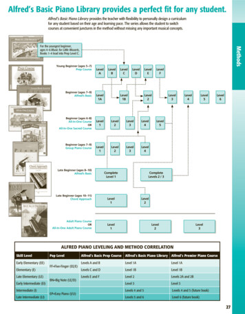
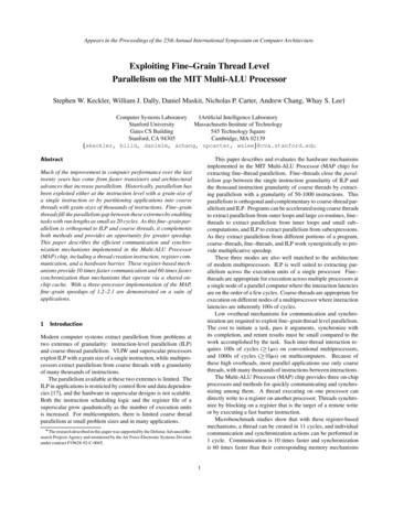
ComponentInteger Units (3)Memory Units (3)16KB Data Cache Banks (2)Floating–point UnitNIF/RouterI/O PadsInstruction Caches (3)EMI 64 entry TLBClock driversSwitch driversMisc. Control/WiringArea( pBp 2 )55.942.436.933.426.826.617.78.35.73.1% oftotal area16.712.711.010.08.18.05.32.51.70.923.1Table 2: Area costs for the components of the MAP chip.Figure 2: Preliminary plot of the MAP chip, measuring 18 pGpa side and containing approximately 5 million transistors.The cluster barrier instruction stalls a thread’s execution until thethreads on the other two clusters have reached a cbar instruction.Threads waiting for cluster barriers do not spin or consume anyexecution resources. The cbar instruction is implemented usingsix global wires per thread to indicate whether a cbar has beenreached, and whether it has been issued. Six wires per threadare necessary in order to guarantee that successive barriers stay insynchrony across all three clusters.onwith memory communication between threads, allowing synchronization on a word by word basis. However, a consumer threadwaiting for a producer will continue to make memory requestswhile spinning, which can slow down other threads trying to access the memory system. An alternative to spinning that can beimplemented in the MAP is to invoke a software handler to retrythe memory access when a synchronization failure is detected inthe memory system. 3 e 9 r Irn w w u AA preliminary layout plot of the entire MAP chip is shown in Figure 2. The chip is 18mm square and consists of approximately 5million transistors in a 5 metal layer, 0.7 m drawn (0.5 m effective) process. The cluster datapath and control modules occupy thebottom 60% of the chip, the network interface (NIF) and router arein the middle 15%, and the memory system is in the top 25%. TheCluster Switch runs horizontally in metal-4 at the midpoint of theclusters and consumes only 8% of the metal-3 and metal-4 routingin the cluster region. However, the wiring congestion near theCluster Switch is significant since the switch runs over the clusterpipeline control modules. The Memory Switch is below the cachebanks in the memory system region and occupies about 6% of themetal-3 and metal-4 routing resources there. Table 2 summarizesthe area costs for the different components of the chip. The targetclock rate for the MAP chip is 100MHz. All of the datapath circuits meet that clock rate, but static timing analysis shows a clockrate of 40MHz for the control logic. The clock rate was reducedin order to avoid performing logic optimizations for speed. Thefinal routing of the chip is currently being completed and tapeoutis scheduled for April 1998.qsr tWu v w r xzyP{ 9x r }W 9 x s The MAP chip uses full/empty bits in aregister scoreboard to determine when values in registers are valid.When an operation issues, it marks the scoreboard for its destination register invalid, and when the result is written, the destinationregister’s scoreboard is marked valid. Any operation that attemptsto use the register while it is empty will stall until the register isvalid. To reduce the amount of interaction between physically distant clusters, an operation that writes to a remote cluster does notmark its destination register invalid. Instead, the consumer mustexecute an explicit empty instruction to invalidate the destinationregister prior to receiving any data. When the data arrives froma remote register write, the scoreboard is marked valid and anyoperation waiting on the register is allowed to issue. However, theproducer must not write the data before the empty occurs. Theempty can be guaranteed to execute first by placing it prior to anunrelated write from the consumer to the producer, or by placinga barrier between the empty and the transfer from the producer.Using register–register communication fuses synchronization withdata transfer in a single operation and allows the consumer to stallrather than spin. Bu { x A}Wrn { 9 I x vSpecific microbenchmarks are used to directly evaluate the fine–grain thread control, communication, and synchronization mechanisms of the MAP chip. The microbenchmarks are written in MAPassembly code and run on both MSIM and the MAP chip registertransfer level (RTL) simulator. MSIM is a functional simulator ofthe MAP implemented in C, and executes 400–1000 MAP cyclesper second, depending on how many clusters are active. The RTL x x u rnx u3 v w x { w u The simplest synchronization mechanismimplemented by the MAP is the cluster barrier instruction cbar.4
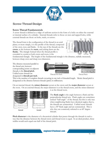
Mastermaster callmaster returnOperationhforkmemoryregisterSlaveslave asterReturn191Total143610Table 3: Latencies for thread invocation. The total time is end–to–end latency of a null remote invocation. Using the hforkinstruction or register communication yields an overhead threetimes smaller than using memory operations.slave returnFigure 3: Components of thread invocation and return.is the logic design of the MAP chip, implemented in Verilog. Itis used for all verification, is exactly cycle accurate to the silicon,and runs less than 10 MAP cycles per second. MSIM was used toverify the logic design in the RTL and is within 5% of the cycleaccuracy of the RTL over the 663 verification programs in theMAP regression suite.OperationMemory (cache ble 4: Communication latencies between threads. P 3 S U W : )¡0 Three methods for starting a thread on a remote cluster, includingone cold start and two standby, are examined. The cold startmethod uses the hfork instruction, which starts the remote threadautomatically with a single instruction executed by the master. Thestandby methods already have a slave thread running in the remotecluster waiting for a new task from the master. The two standbymethods differ in how the master and slave communicate with oneanother, using either registers or memory.Figure 3 shows the four components of a null thread call andreturn. The master call overhead is the number of cycles thatthe master must spend executing instructions to create the newthread. The slave invoke latency is the time from the beginningof the master call to the execution of the slave’s first instruction.The slave return latency is the time for the slave to signal to themaster. Finally the master return is the overhead for the master toresynchronize with the slave.Table 3 summarizes the components of latency for each of thethree methods. The hfork instruction and the standby registermethod are the most efficient, with only 1 cycle of overhead forthe master at the call and return. Standby register is a little fasteroverall as the slave invocation time is shorter. Standby memory ismore than three times worse than the register version because ofthe memory spin loops the master and slave use to synchronize.until the value is written and the scoreboard is marked full.There are two components to the efficiency of cross clustercommunication. The producer overhead is the number of cyclesthat the producer must spend initiating the transfer. The transferlatency is the total time from the producer initiation to the useby the consumer, and includes the producer overhead. Table 4shows the producer overhead and transfer latency for memory andregister communication. Before transferring the data, the memoryversion must first compute the address of the communication location, which takes 3 cycles. In the register version, the remotelocation for the data is encoded in the instruction performing thetransfer, resulting in only a single cycle producer overhead. Thememory version also has a 10 cycle transfer latency, including theproducer overhead and two memory latencies, one each by theproducer and consumer. If either memory access misses in thecache, the transfer latency will be significantly longer. Registercommunication has only one additional cycle of latency for theCluster Switch traversal, and the consumer is able to use the dataimmediately. ª n Not all synchronization can be easily expressed using a producerconsumer model. A barrier can be used to conglomerate severalsynchronizations into a single action. Fast barriers reduce theoverhead of using parallelism, which is vital if the parallelismto be extracted has short task execution times between synchronizations. Four implementations of barriers across three clustersare examined: memory, register, condition-code, and CBAR. Thememory implementation uses four memory locations; one locationholds the barrier counter, and each thread has its own location onwhich to spin. Upon reaching the barrier, each thread performsa fetch and increment on the counter, using the MAP’s memorysynchronization bits to atomically lock and unlock the counter. Ifthe barrier count is less than 2, the thread begins spinning on itsown memory location. Otherwise, the other threads have reachedthe barrier, the count is reset to zero, and the spinning threads’memory locations are marked full, releasing them. P b¡c A§e§e 9 A Communication latency and overhead are evaluated by using aproducer-consumer microbenchmark. Both memory and register mechanisms are examined by passing a value back and forthbetween two clusters. The memory version uses two memory locations, one for each communication direction. Spin locks using theMAP’s memory synchronization bits implement synchronizationbetween the threads. The producer stores its value to the targetlocation, and marks the memory location full, while the receiverspins on the location, waiting for the data to arrive. The registerversion uses the empty instruction and remote register writes.The producer empties its receiving register and writes the value tothe consumer’s register file. The consumer stalls on the register5
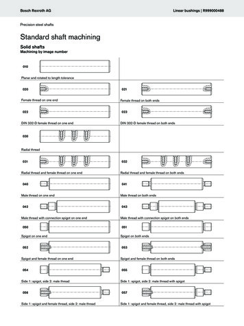
Barrier MethodMemory (cache hit)RegisterCondition CodeCBARfor(i 0; i global num; i ) {res1 sub loop(sub num, const);res2 sub loop(sub num, const);res3 sub loop(sub num, const);total res res1 res2 res3;}Latency61651Table 5: Latency to execute a barrier across all three clusters. Evenwith an on-chip cache, synchronizing using memory is more thanten times as expensive as using registers or the cbar instruction.Figure 4: Pseudocode for synthetic benchmark. Each instanceof sub loop is executed on a different cluster for the parallelmeasurements.Synthetic ProgramThe register barrier microbenchmark consists of an even phasebarrier, followed by an odd phase barrier. Upon reaching thebarrier in an even phase, a thread empties its odd phase registers,and writes into the even phase registers of both of its neighborthreads. It then reads from its own even phase registers, stallinguntil they have been written by the neighbors. Two registers perphase are necessary to allow each of the neighbors to communicateindependently. The Condition Code barrier is similar except thatwith the broadcast condition code registers, only one instruction isrequired to signal to both neighbor threads. The CBAR barrier usesthe cbar instruction, without requiring any registers or auxiliaryinstructions to be executed.Each mechanism is implemented in a simple program that does100 successive barriers. The time per barrier in the steady stateis measured and shown in Table 5. The cbar instruction is thefastest and can complete a barrier every cycle. The register andcondition code barriers are similar, with Condition Code being onecycle faster since only one write is necessary to communicate withboth neighbors. The memory barrier requires 61 cycles, even withall accesses hitting in the cache. For each thread, approximately20 cycles are needed for the control overhead of testing the barriercounter, while the remaining cycles are consumed contending forthe on-chip cache and waiting for the other threads to arrive at thebarrier. In order to exploit fine–grain parallelism with task lengthsin the 10s of cycles, long latency memory-based barriers cannotbe used.SEQPPC REGPPC MEMDescriptionBaseline sequentialParallel with register synchronizationParallel with memory synchronizationTable 6: Synthetic benchmarks.master, which performs a join before beginning another iterationof the outer loop. The versions to be compared are enumerated inTable 6.Figure 5 shows the time for one iteration of the outer loop asa function of the granularity of the inner loops, normalized to thesequential execution time. The granularity, in turn, is a function ofthe number of inner loop iterations, which is varied from 0 to 30.When no iterations are executed within sub loop, the procedurecall overhead and test inside the procedure still requires 19 cycles.Each increment in grain size corresponds to an additional loopiteration in each subroutine. At the smallest grain size, PPC REGis 1.6 times faster than SEQ, while PPC MEM is 1.2 times slower,due to the additional cost for the master to store the argumentsinto memory and the slave to retrieve them. Both PPC REG andPPC MEM improve substantially as more work is done insidethe inner loops, but their execution time relative to sequentialflattens out above granularities of 110 cycles as they approachthe maximum of 3 times speedup. PPC REG still maintains anadvantage over PPC MEM, but that diminishes as the granularityincreases.The most significant component of the overhead is in startingthe slave threads. As shown in Figure 6, the cost to pass eachadditional argument from the master to a slave is not substantial.For PPC REG, approximately two cycles are required for eachadditional argument, one cycle for each slave thread. PPC MEMrequires almost four cycles per additional argument, two cycles
M-Machine Multicomputer, is intended to exploit parallelism at a spectrum of grain sizes, from instruction level parallelism to coarser grained multi-node parallelism [5]. It employs a set of fast communication and synchronization mechanisms that enable executionof fine-grainparallel programs. Figure 1 shows a block diagram of the MAP chip .