Transcription
Reducing Methane Emissions:Best Practice GuideEngineering Design and ConstructionNovember 2019
DisclaimerThis document has been developed by the Methane Guiding Principles partnership. The Guide provides asummary of current known mitigations, costs, and available technologies as at the date of publication, butthese may change or improve over time. The information included is accurate to the best of the authors’knowledge, but does not necessarily reflect the views or positions of all Signatories to or SupportingOrganisations of the Methane Guiding Principles partnership, and readers will need to make their ownevaluation of the information provided. No warranty is given to readers concerning the completeness oraccuracy of the information included in this Guide by SLR International Corporation and its contractors,the Methane Guiding Principles partnership or its Signatories or Supporting Organisations.This Guide describes actions that an organisation can take to help manage methane emissions.Any actions or recommendations are not mandatory; they are simply one effective way to help managemethane emissions. Other approaches might be as effective, or more effective in a particular situation.What readers choose to do will often depend on the circumstances, the specific risks under managementand the applicable legal regime.
ContentsSummary.2Introduction.3Example engineering and design strategies.5Checklist. 14Appendix 1: mitigation strategies that can be used with in the design stage. 15References. 181
SummaryEngineering and design can play a vital role inreducing methane emissions, and are the firstline of defense. Also, it is usually substantiallycheaper to reduce emissions during the designstage than by adapting systems later or as part ofmaintenance. In many cases, methane emissionscan be eliminated by design. If this is not feasible,venting and leaks may be minimized through theeffective design of systems. This may includedesigns that reduce the amount of methaneleaked or vented and fuel used or, as a last resort,incorporating a control device to control methane.General design principles to reduce methaneemissions are as follows;Best practice for reducing methane emissionsfrom energy use in oil and gas operationsUse electric, mechanical and compressedair equipment where possibleCentralize facilitiesUse pipelines to transport oil and naturalgas from facilitiesRecover methane for beneficial useUse alternative low-emission and lowmaintenance equipment2
IntroductionEngineering and the design of systems can bea gas-fired generator may be needed if the siteused to reduce methane emissions before newdoes not have mains electricity.facilities begin operations or when existing facilities2. Centralize facilitiesare modified. The design phase provides the bestopportunity to identify methane reductions. It is alsoCentralizing facilities may eliminate sourcesusually less expensive to apply reduction strategiesof methane emissions and allow morein the design phase than to have to modify theefficient equipment and processes to be used.facility. The system’s engineer should consider theFor example, a centralized facility may usefollowing strategies to reduce methane emissions.a single hot-oil heater to provide heat for allThe strategies are listed in order of priority.equipment in the facility instead of a separateheater for each piece of equipment.1. Eliminate sources of methane2. Reduce the amount of methane emitted and theCentralizing facilities can also make methane-amount of fuel usedreduction or recovery equipment more3. Control remaining sources of methaneeconomically viable. For example, an oilMost engineering solutions will be specific tothat can take production from surroundingstabilizer or multi-stage separation systemfacilities to reduce storage tank emissions.a company’s operations and facilities, and willSimilar systems at each individual site may notevolve as technology does. Any design needsbe available or economical on a smaller scale.to prioritize integrity, safety, fire-protection andregulatory requirements over reducing emissions.3. Use pipelines to transport oil and natural gasEffective design strategies to reduce methanefrom facilitiesemissions throughout the natural-gas supply chainare discussed in detail below.Using natural-gas pipelines makes sure that1. Use electric, mechanical and compressed-airflaring or venting at production facilities.methane is sold and reduces or eliminatesequipment where possibleLiquid pipelines can eliminate methaneNatural gas pneumatic devices are aemissions from storage tanks and truck loading.significant source of methane emissions inThese pipelines also allow equipment tosome operations in the oil and gas industry.be centralized.Using electric, mechanical or compressed-air4. Recover methane for beneficial usedevices can completely eliminate emissionsfrom pneumatic devices.Natural-gas recovery should be prioritized overIf there is no mains electricity at a remote site,or used as fuel on-site. Vapor-recovery unitsa single gas-fired electricity generator or aircan be installed to boost the pressure of low-compressor can be used instead of severalpressure gas for sales. Gas can also be directedpneumatic devices. Using electric compressorsto a low-pressure fuel system or local gatheringand pumps instead of gas-fired equipment canline. Some operators will use it to generatereduce natural gas used as fuel and increaseelectricity to run air compressors or potentiallythe amount that can be sold. Electric motors aresell electricity to the local grid. Gas can also bealso more reliable than gas-fired engines, butinjected back into the well to improve recovery.flaring or venting. The natural gas can be sold3
IntroductionFor some sources and processes, commerciallyavailable programs and models are widely usedto simulate hydrocarbon treating, processing andhandling processes. Examples of these programsare ProMax or Aspen HYSYS , or simplifications ofEngineering design should prioritize recoveringnatural gas if possible.5. Use alternative low-emission and lowmaintenance equipmentSome processes or equipment can beeliminated or replaced with alternativeno-emission or low-emission systems.Alternative systems should be consideredif they can meet the requirements of theproject. For example, methanol injection ordessicant dehydrators are some low-emissionalternatives to traditional glycol dehydrators.those models in estimation tools such as E&P Tanksdeveloped by The American Petroleum Institute(API). Models can also be used to characterizemethane emissions from glycol dehydrator systemvents, and there are simplification tools such asthe Gas Technology Institute (GTI) GLYCalcTMprogram. An advantage to a model is that sitespecific conditions can be entered, so that eachindividual process can be accurately simulated.Some jurisdictions even require certain modelsto be used. An example is for reporting tank flashemissions under the US EPA’s GHG ReportingRule, or under the US New Source PerformanceStandard, Subpart OOOOa.Low-maintence equipment should also beconsidered to reduce venting natural gas inorder to perform maintenance activities.Quantifying emissionsQuantification methods for methaneemissions deliver a rate, such as mass per time(e.g. kilograms per hour) or volume per time(e.g. standard cubic meters per hour), and canbe produced by engineering estimations, bydirect measurement of the methane sources,or by use of models. In the design phase thereare three basic techniques for quantifyingemissions. These are listed below, from mostaccurate to least accurate.Less-detailed equations for estimating emissionsmay be used. These equations require site-specificinformation to be used to characterize emissions.Equations may use a variety of information suppliedlocally to estimate the rate from certain processesor activities.The easiest but also least accurate technique forestimating emissions is to use information from theequipment manufacturer and ‘emission factors’,where emissions per activity (such as a quantityof gas per year per equipment type) is simplymultiplied by the number of pieces of equipment. Modeling (for tank-flash emissions andglycol dehydrator regenerator emissions)using a process simulation program topredict emissions based on first principlesand equations. Emission-calculation equations may use avariety of information, from the equipmentmanufacturer or gathered locally, to estimatethe rate from certain processes or activities.4
Example engineering and design strategiesThis guide is not intended to detail all design recommendations that could reduce methane emissions, butrather to give some examples of best practice that can be followed to reduce methane emissions. Many ofthe mitigation strategies detailed in the other best practice guides can be used for design and engineeringpurposes. Those strategies are not detailed in this guide. The strategies in the table below are covered inthis guideline.Engineering anddesign strategyEliminatessources ofmethaneemissionsReducesventing, leaksor energy useControlsmethaneDesignStrategyCategory1. Siting of utilities andcentralization1, 2, and 32. Modular design53. Eliminating fugitivecomponents54. Location of fire-gate4valves and isolationvalves5. Secondary and tertiaryseparation46. Tankless design3 and 57. Storage tank design58. Using electriccompressors19. Pig ramps andjumper lines4 and 510. Using methanol toprevent hydrates511. Amine unit flash tank412. Acid gas control device55
Example engineering and design strategiesEngineering and designstrategy 1: Siting of utilitiesand centralizationReduction in emissions andeconomic evaluationReductions and economic evaluations for mitigationoptions that require a power supply are detailed inthe other engineering and design strategies.Oil and natural gas are produced in remotelocations, often with limited gas-gatheringpipelines and power supply. Many facilities relyon heaters, engines, and pneumatic devices thatuse natural gas as fuel and motive gas. Also, theysometimes need to flare or vent natural gas.In continental US in 2017, the cost of pipelineswith a diameter of less than 20 inches (500mm) ranged from US 29,000 per inch-mile toUS 167,000 per inch-mile ( 710 to 4,086 permm-km)1. In continental US in 2013, the cost ofabove-ground power lines is estimated to havebeen between US 285,000 to 390,000 per mile( 177,000 to 242,000 per km)2.Where technically and economically feasible, thedecision on where to locate a site should take accountof the proximity to existing power supplies andpipelines, and the design of facilities should reduce.Engineering and designstrategy 2: Modular designthe use of natural gas as a fuel and instead useelectrical equipment. If a facility cannot be locatednear existing infrastructure, power supplies andpipelines should be brought to the facility if this istechnically and economically feasible.Well-production rates decline over time, especiallyfor unconventional wells. Production-equipmentsized for initial production will not be needed asthe production from the well falls. Modular designallows for equipment to be scaled down asproduction rates decrease. Removing equipmentis likely to reduce the number of fugitive leaks, aswell as the amount of natural gas used to drivepneumatic devices. Examples of modular designincludes using skid-mounted equipment that canbe easily removed and replaced, having severalsmaller storage tanks instead of one large storagetank, and having several smaller compressorsinstead of one large compressor.Operators should, where practicable, centralizeproduction facilities for large-scale developments.Centralization is where no (or minimal) hydrocarbontreating, processing and handling of liquids occursat the well pad, and separation, treating, storageand handling are instead carried out at a centrallylocated facility. The centralized facility can usemitigation measures that may not be economical atsmaller facilities.Operating requirementsOperating requirementsBack-up systems – such as emergency generators,flares and transporting liquids by truck – should beconsidered if frequent interruptions to the powersupply are anticipated. Extra treatment processessuch as dehydration, acid-gas removal and oilpolishing may also be needed on-site to make surethe product meets the specifications necessary tobe transported in a pipeline.Facilities need to be large enough to have multiplepieces of equipment rather than one large pieceof equipment. Operators should regularly evaluateproduction rates to decide when equipment shouldbe removed.6
Example engineering and design strategiesReduction in emissions andeconomic evaluationReduction in emissions andeconomic evaluationReductions and costs depends on the equipment.One operator estimated savings of 4,200 Mscf(thousand standard cubic feet) per year (120,000m3 (cubic meters) per year) of natural gas for eachstorage tank removed3. Upfront equipment costsmay be slightly more than traditional facilitiesdue to extra equipment needing to be bought.For large-scale developments, modular design mayalso result in cost savings as removed equipmentcan be used at other facilities.During the design phase, the cost of replacingflanges or threaded connections with welds isminimal. Emissions from flanges are estimatedto be between 5.7 x 10 -6 and 0.39 x 10 -6 kgper hour per flange4. Emissions from threadedconnections are estimated to be between 1.0 x10 -5 and 0.75 x 10 -5 kg per hour per connection4.Welded connections are not expected to leak.Engineering and designstrategy 4: Location of firegate valves and isolation valvesEngineering and designstrategy 3: Eliminatingfugitive leaksIsolation valves are used to isolate equipment suchas compressors or separation vessels so that theycan be depressurized (blowdown) for maintenanceand repair purposes. Having the valves as close tothe equipment as possible reduces the amount ofmethane released during blowdowns.Threaded connections and flanges are used toconnect piping, equipment and other componentssuch as valves. Threaded connections arecommonly used on piping with a diameter of twoinches (50 mm) or smaller. Flanges are commonlyused on piping with a diameter larger than twoinches. There is the potential for natural gas toleak from threaded connections and flanges.These connections can sometimes be replaced withwelded connections, which are much less likelyto leak.Fire-gate valves are used to isolate a facility duringan emergency shutdown. Having the fire-gatevalves as close as possible to the first and last pieceof equipment in the facility also reduces the amountof methane released during emergency shutdowns.Operating requirementsOperating requirementsThe location of the valves may be dictated bysafety or fire protection regulations.Threaded or flanged connections are needed whenconnecting valves or other components that needto be removed or replaced frequently, in order toavoid having to cut the piping.Reduction in emissions andeconomic evaluationDuring the design phase, the cost of relocatingvalves is minimal. Methane reduction is based onthe pressure of the pipeline or equipment and theamount of piping that needs to be depressurizedduring emergencies or maintenance, and thefrequency of blowdown events.7
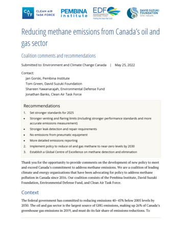
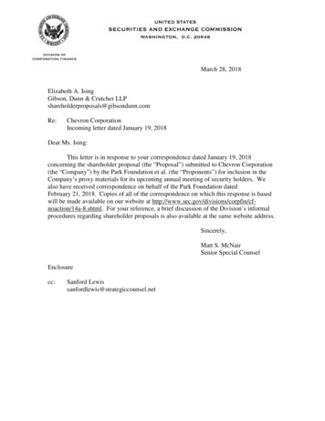
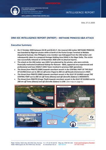
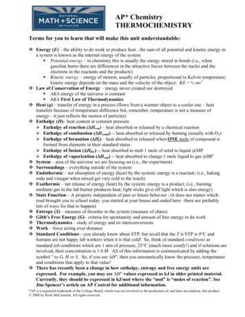
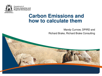
Example engineering and design strategiesEngineering and design strategy 5: Secondary andtertiary separationOil and condensate need to be separated from natural gas at production facilities, compressor stations andprocessing plants. This separation usually occurs at high pressure, greater than 100 psig (700 kPa). When theoil or condensate is transferred from high-pressure separators to storage tanks at atmospheric pressure,‘flash gas’ is released. The flash gas is typically vented from the storage tank or flared. Secondary and tertiaryseparation can be used to recover some or all of the flash gas and minimize flashing within storage tanks.Figure 1 shows secondary and tertiary separators represented as a heater treater and vapor-recovery tower(VRT) at a production facility.Figure 1: Secondary and tertiary separators at a production facilityPressureReliefValveVRU(Optional)Gas tosales3-PhaseSeparatorCondensateTanksHeater Treater(Optional)VRT(Optional)Vapor Control ownValveBlowdownValveControl DeviceKnockoutVesselThiefHatchSource: Reference5The practice of having secondary and tertiary separation can be used for compressor scrubbers as wellwhere condensed condensate is routed to lower-pressure vessels instead of non-pressurized storage tanks.An example is a configuration of cascading scrubbers, as shown in Figure 2, where the high-pressurecondensate is routed to the next lower-pressure scrubber, and only the inlet scrubber is directed to tanks.8
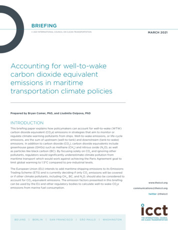
Example engineering and design strategiesFigure 2: Cascading scrubber system on a compressorGas to Pipeline3rd StageCooler3rd StageCompressionQQQ2nd StageCooler2nd StageCompressionQQQQQ2nd StageSuctionScrubberQAtmospheric Storage Tank1st StageScrubberInlet GasQQ3rd StageScrubberQ1st StageCooler1st StageCompressionQDischargeScrubberQLiquid to tanksOperating requirementscascading scrubber dumps can reduce flash gasfrom the storage tank by 98.7% and increase theamount of gas that can be sold by 1.2%7.Vapor-recovery units (VRUs) need to be usedto recover gas from the low-pressure vessels.The use of electric VRUs is preferred due to theirability to work for a wider range of flow rates thancompressors driven by natural gas engines.Engineering and designstrategy 6: Tankless designReduction in emissions and economicevaluationStorage tanks at atmospheric pressure are usedto hold crude oil, hydrocarbon condensate andproduced water (and mixtures of these) before theyare transferred from the site. The EPA estimatesthat methane from atmospheric storage tanksaccounts for about 10% of the methane fromthe oil and gas industry8. One design techniqueis to eliminate the storage tank altogether.This ‘tankless’ design can be applied in variousways through production, gathering andprocessing operations. Examples of tankless designA case study from Occidental Petroleum estimatedthe cost of a secondary separator and VRTwith VRUs to be USD 100,000 to 200,0006.Payback periods are typically one to five months6.The cost of cascading scrubbers is not known, butis likely to be minimal due to only minimal changesneeding to be made to piping. Emission reductionsdepend on the composition of the gas, but onecase study by Kent Pennybaker estimated that9
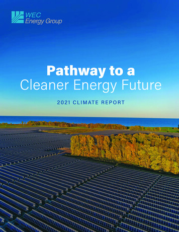
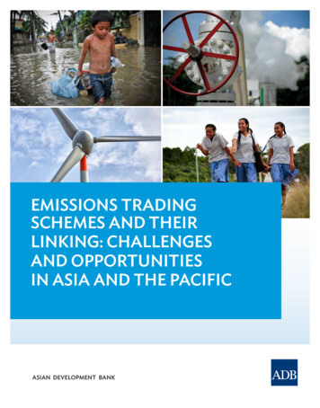
Example engineering and design strategiesOperating requirementsfrom a production, gathering and processingperspective are as follows.Tankless design requires access to a pipeline.The liquid may need to meet certain specificationsto be transported in a pipeline. A method to re-treator store liquid that does not meet the specificationsmay be needed. It may also be necessary to provideemergency storage-tank capacity so wells canproduce when the facility is shut out of the pipeline. Production – liquid from the separator istransferred directly to a pipeline through anLACT (lease automatic custody transfer) unit orto a surge vessel operating at near atmosphericpressure. The surge vessel is rated for a pressurefar above atmospheric pressure. The largeoperating range allows the vessel to accommodatefluctuations in production and changes to pressurein the tank due to flashing. Vapor generated in thesurge vessel is compressed and sent to a pipeline.Electricity at the facility is also important as it allowselectric pumps and VRUs to be used. More frequent‘pigging’ of the pipeline may be needed for systemsthat use the pump-around technique at compressorFigure 3 shows an example production facilityusing a tankless design.stations. At natural-gas processing plants, addingcondensate to NGLs needs to be evaluated site bysite to make sure that the NGLs can still meet thebuyer’s or the pipeline’s specifications.Figure 3: A production facility using atankless designReduction in emissions andeconomic evaluationTank emissions can be eliminated almostcompletely by using a tankless design.One operator reported a reduction of more than90% in emissions by using tankless facilities9.Costs are likely to be less than traditional facilitiesdue to reduced equipment and size of sites.Engineering and designstrategy 7: Storage tank designSource: Reference9 Gathering – at a compressor station, liquid froma ‘slug catcher’ is routed directly to the facilityoutlet using an electric pump or blow case.The liquids are then processed at a downstreamfacility such as a natural-gas processing plant.The control systems for storage tanks can bedifficult to design due to their very narrowoperating pressure range, typically less than 1psig (7 Kpa). Snap-acting valves, plunger-liftsystems and pigging can result in variationsin liquid and vapor flow rates into the controlsystem. The control system for storage tanks atatmospheric pressure needs to be adequatelydesigned so that the pressure-relief devices donot vent to the atmosphere and all vapors fromthe storage tank are directed to the control device Processing – at a natural-gas processing plant,liquid from a slug catcher is stabilized and mixedwith natural-gas liquids (NGLs) in pressurizedtanks or sent directly to a pipeline for NGLs.10
Example engineering and design strategiesReduction in emissions andeconomic evaluationor VRU during reasonable peak production rates.The design needs to take account for the maximumvapor and liquid flow rates, which may be differentfrom the daily production rates, especially forsystems with snap-acting valves or wells onplunger lift. The design should assess the capacityof the control device, and pressure drop throughthe vapor-collection piping.Electric compressors are estimated to save 2.11Mscf of gas per horsepower (80,000 m3 perkilowatt) of the compressor. The cost dependson the size of the compressor. One case studyestimated the initial outlay was 1,500,000for a 1,750 horsepower (1,300 kW) engine.Annual operating costs were approximately equalto the initial capital cost and are mostly due to thecost of electricity3.Operating requirementsModeling may be needed to determine the peakstorage pressure.Engineering and designstrategy 9: Pig ramps andjumper linesReduction in emissions andeconomic evaluationThe cost to carry out a design assessment onstorage-tank control systems in continental US isestimated to be 550- 360 per facility10.A pig (pipe inspection gauge) is used to inspectpipelines and push accumulated liquids throughthem to downstream facilities. A pig trap at thebeginning of the pipeline is depressurized to allowthe pig to be inserted into the pipeline. The pigtrap is then pressurized to send the pig downthe pipeline. The pig is received into another pigtrap at the other end of the pipeline (the receiver).In the receiver, some liquid is trapped in front ofthe pig as well as on the pig itself. When the pigis removed, methane is released due to flashingfrom the trapped liquid. Pig ramps allow liquids infront of and on the pig to be captured and sent tothe pipeline before the pig trap is depressurized,reducing flashing emissions. Jumper lines canpartially depressurize the trap to reduce ventingfrom pigging operations.Engineering and designstrategy 8: Using electriccompressorsCompressors are used to move natural gas throughpipelines, as well as to recover gas from lowpressure systems. Engines that run on naturalgas are commonly used to drive compressors.An alternative is to use electric motors to drivecompressors. Natural-gas engines can only runat a minimum of 50% of their maximum power.Electric motors with variable frequency drives canrun at very low loads. Electric motors also need lessmaintenance than natural-gas engines and so aremore reliable.Operating requirementsOperating requirementsPig ramps are mostly passive devices, but extratime may be needed from the pig being receivedto it being removed from the receiver to allow theliquids to drain back to the pipeline. A low-pressuresystem also needs to be available on-site to acceptthe gas from the pig trap.A power supply is needed to run electriccompressors. Large compressors may need highvoltage lines. A back-up generator may be neededfor areas where the power supply is not reliable.11
Example engineering and design strategiesEngineering and designstrategy 11: Amine unitflash tankReduction in emissions andeconomic evaluationMPLX estimates that using pig ramps and jumperlines can reduce emissions from pigging by upto 85%11at a cost of approximately US 8,175per facility11.Sour gas, which contains high concentrationsof sulfur compounds, mainly hydrogen sulfideand carbon dioxide, needs to be treated toremove those compounds. Amine units are onemethod of removing those compounds. The mostcommon amine used is methyl diethanolamine.The amine is circulated through a tower andabsorbs the compounds from pressurized naturalgas. Amine also picks up methane from the gas.The amine is then sent to a regenerator to removethe carbon dioxide and sulfur so the amine can bereused. The removed carbon dioxide and sulfuris called acid gas which is normally vented tothe atmosphere.Engineering and designstrategy 10: Using methanol toprevent hydratesDuring cold weather, water can freeze and formhydrates in pipelines, which can inhibit the flowof natural gas. When hydrates are a concern,a glycol dehydrator is typically used to removewater from the natural gas. Glycol also absorbssome methane, which is vented to the atmosphereduring glycol regeneration. Methanol can beused instead of glycol dehydration to inhibit theformation of hydrates. Methanol is simply injectedinto the gas before it enters the pipeline and isremoved downstream.A flash tank can be installed upstream of theregenerator to recover some of the methanepicked up by the amine. The flash tank is at alower pressure than the tower and some of themethane flashes when the amine drops in pressureas it enters the flash tank. The methane can berecovered to a low-pressure system such as thefacility fuel system.Operating requirementsMethanol needs to be injected from an atmospherictank into the pressurized natural gas using a pump.The pumps are typically easy to use and are solarpowered. Methanol will need to be delivered toeach facility by truck.Reduction in emissions and economicevaluationReductions depend on the system, but areexpected to be 90%, similar to that of installing aflash tank on a glycol dehydration unit3. Costs varydepending on the size of the tank installed.Methanol needs to be removed from the naturalgas during processing, usually during normalseparation and acid-gas removal.Reduction in emissions andeconomic evaluationEmission reductions are estimated at 800 Mscf(22,500 m3) of natural gas per facility. The costis estimated at US 2,250 per installation plusoperating costs of US 3.45 per MMscf (US 121per 106 m3) of natural gas3.12
Example engineering and design strategiesEngineering and designstrategy 12: Acid gascontrol deviceAcid gas discharged from treatment with amineis typically very high in carbon dioxide and sulfur,with a small concentration of hydrocarbons.The acid gas may need to be controlled, for safetyreasons or to meet environmental standards.Acid gas with a high proportion of carbon dioxidedoes not have enough heat content (calorific value)to be burned in a flare or combustor. ‘Assist gas’,typically fuel gas, can be added to the acid gasto bring the heat content up to at least 300 Btu/scf (11.2 MJ/scm)12. The assist gas needed may bequite large depending on the volume of acid gasto be recovered. Direct thermal oxidizers may beused to oxidize methane, but traditional thermaloxidizers need a large volume of fuel to keep thecombustion chamber at the required temperature.‘Recuperative’ or ‘regenerative’ thermal oxidizersare more fuel-efficient ways of controlling acid gas.These control devices recover waste heat, reducingthe amount of fuel needed to keep the combustionchamber at a high enough temperature.Operating requirementsThermal oxidizers need a special design forcorrosive gases like acid gas. Thermal oxidizers alsoneed power to run fans, controls and valves.Reduction in emissions andeconomic evaluationReductions depend on the size of the amine unit.One company reported saving up to USD 750,000per year in fuel costs by replacing a thermaloxidizer with a regenerative thermal oxidizer13.13
ChecklistThe following checklist allows you to assess your progress in reducing methane emissions through the designof systems.ActivityCompletedInclude methane reduction in standard designpracticeUse electric, mechanical and compressed-airequipment where feasibleCentralize facilitiesUse pipelines to transport oil and natural gasfrom facilitiesRecover methane where feasibleControl methane where recovery is not feasibleUse alternative low-emission equipment andprocessesUse alternative low-maintenance equipment andprocesses14Percentage ofall equipment orprocesses in thisprogram
Appendix 1: mitigation strategies that canbe used with in the design stageS
Engineering and design can play a vital role in reducing methane emissions, and are the first line of defense. Also, it is usually substantially cheaper to reduce emissions during the design stage than by adapting systems later or as part of maintenance. In many cases, methane emissions can be eliminated by design. If this is not feasible,