Transcription
SOLAR AND WASTE HEAT DESALINATIONBY MEMBRANE DISTILLATIONCollege of EngineeringUniversity of Texas at El PasoEl Paso, TX 79968Agreement No. 98-FC-81-0048Desalination and Water Purification Research and DevelopmentProgram Report No. 81April 2004U.S. Department of the InteriorBureau of ReclamationDenver OfficeTechnical Service CenterEnvironmental Services DivisionWater Treatment Engineering and Research Group
Form ApprovedOMB No. 0704-0188REPORT DOCUMENTATION PAGEPublic reporting burden for this collection of information is estimated to average 1 hour per response, including the time for reviewing instructions, searching existing data sources, gathering andmaintaining the data needed, and completing and reviewing the collection of information. Send comments regarding this burden estimate or any other aspect of this collection of information,including suggestions for reducing this burden to Washington Headquarters Services, Directorate for Information Operations and Reports, 1215 Jefferson Davis Highway, Suit 1204, Arlington VA22202-4302, and to the Office of Management and Budget, Paperwork Reduction Report (0704-0188), Washington DC 20503.1. AGENCY USE ONLY (Leave Blank)2. REPORT DATE3. REPORT TYPE AND DATES COVEREDApril 2004Final4. TITLE AND SUBTITLE5. FUNDING NUMBERSAgreement No. 98-FC-81-0048Solar and Waste Heat Desalination by Membrane Distillation6. AUTHOR(S)John Walton, Huanmin Lu, Charles Turner, Sergio Solis and Herbert Hein7. PERFORMING ORGANIZATION NAME(S) AND ADDRESS(ES)8. PERFORMING ORGANIZATIONREPORT NUMBERCollege of EngineeringUniversity of Texas at El PasoEl Paso, TX 799689. SPONSORING/MONITORING AGENCY NAME(S) AND ADDRESS(ES)10. SPONSORING/MONITORINGAGENCY REPORT NUMBERBureau of ReclamationDenver Federal CenterP.O. Box 25007Denver, CO 80225-0007DWPR No. 8111. SUPPLEMENTARY NOTESDesalination and Water Purification Research and Development (DWPR) Program12a. DISTRIBUTION/AVAILABILITY STATEMENT12b. DISTRIBUTION CODEAvailable from the National Technical Information Service, Operations Division,5285 Port Royal Road, Springfield, Virginia 2216113. ABSTRACT (Maximum 200 words)In this study, the desalination performance and O&M procedures of an air-gap type membrane distillationsystem was tested using low-grade thermal energy (between 13 and 75 ºC) supplied by a salt-gradient solarpond. The research included measuring the flux per unit area of membrane surface and separation of ionsover a range of feedwater salinities and temperature as well as an assessment of membrane fouling.15. NUMBER OF PAGES14. SUBJECT TERMS--thermal desalination, solar pond, waste heat, membrane distillation, brackish groundwater28 appendices16. PRICE CODE17. SECURITY CLASSIFICATIONOF REPORT18. SECURITY CLASSIFICATIONOF THIS PAGE19. SECURITY CLASSIFICATIONOF ABSTRACTULULULNSN 7540-01-280-550020. LIMITATION OF ABSTRACTULStandard Form 298 (Rev. 2-89)Prescribed by ANSI Std. 239-18298-102
SOLAR AND WASTE HEAT DESALINATIONBY MEMBRANE DISTILLATIONJohn WaltonHuanmin LuCharles TurnerSergio SolisHerbert HeinCollege of EngineeringUniversity of Texas at El PasoEl Paso, TX 79968Agreement No. 98-FC-81-0048Desalination and Water Purification Research and DevelopmentProgram Report No. 81April 2004U.S. Department of the InteriorBureau of ReclamationDenver OfficeTechnical Service CenterEnvironmental Services DivisionWater Treatment Engineering and Research Group
Mission StatementsU.S. Department of the InteriorThe mission of the Department of the Interior is to protect and provide access to ourNation's natural and cultural heritage and honor our trust responsibilities to Indian tribesand our commitments to island communities.Bureau of ReclamationThe mission of the Bureau of Reclamation is to manage, develop, and protect water andrelated resources in an environmentally and economically sound manner in the interest ofthe American public.Federal DisclaimerThe information contained in this report regarding commercial products or firms may notbe used for advertising or promotional purposes and is not to be construed as anendorsement of any product or firm by the Bureau of Reclamation.
ACKNOWLEDGMENTSThis research was sponsored by the Desalination and Water Purification Research andDevelopment Program, Bureau of Reclamation. The University of Texas at El Paso (UTEP)Department of Civil Engineering wishes to thank Bruce Foods Corporation for providing spaceand facilities at the El Paso solar pond.A number of undergraduate students from UTEP assisted in the project, including BeckyLozoya, Adam Lozoya, Hector Sepulveda, and Al Salcedo.
TABLE OF CONTENTS1.0 Introduction.11.1 Overview of Technology .11.2 Experimental Setup.31.3 Experimental Plan.52.0 Conclusions and Recommendations .62.1 Conclusions .62.2 Recommendations .73.0 Results.83.1 Flux.83.2 Energy.103.3 Quality - Wetting of the Membrane .124.0 Analysis.164.1 Variables Controlling System Response .164.2 Heat Transfer Limited Model .184.3 Projected Efficiency of Membrane Distillation.23References.27Appendix A - Performance Data for October 5, 1999Appendix B - Experimental Data for November 11-12, 1999Appendix C - Performance for Salt ConcentrationsAppendix D - Experimental Data for December 17, 1999TABLES1. Properties of water tested in experimental matrix .52. Cost estimate for fully developed membrane distillation treatment. .26FIGURES1.2.3.4.Schematic of air-gap membrane distillation .2Flow schematic .4Modified SCARAB membrane distillation system.4Production as a function of hot side temperature and temperaturedrop for pure water.85. Production as a function of hot side temperature and temperaturedrop for 0.6 molar water. .9iii
22.23.24.25.ivFlux at 50 to 60 C hot side temperature as a function of molality. .9Influence of recirculating water flow rate.10Comparison of performance at low temperatures.11Economy ratio as influenced by molality. .11Capillary pressure. .12Quality as influenced by flux.13History of membrane leakage. .13Ground water results. .14Percent removal of dissolved solids from ground water.14Vapor pressure of pure water and concentrated brine. .16Diffusion of water vapor across a hypothetical 1-mm air gap as a functionof temperature drop at three different hot side temperatures.17Minimum temperature drop required to begin flux based uponthermodynamic limit.18Comparison of measured and modeled results .20Predicted system efficiency as a function of source water salinity. .21Predicted flux at two temperature drops. .21Temperature polarization coefficient for a total temperature dropof 30 C. .22Predicted temperature drop in the system at a total temperaturedrop of 30 ºC .22Membrane distillation with heat recovery. .24Economy ratio (heat energy used for desalination/total heatenergy input) at different transmembrane temperature drops.25Comparison of membrane distillation and dewvaporation at a hotside temperature of 80 ºC and a temperature drop of 5 C. .25
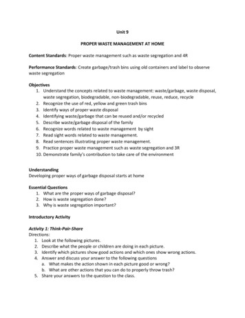
1.0 Introduction1.1Overview of TechnologyMembrane distillation (MD) is an emerging technology for desalination. Membrane distillationdiffers from other membrane technologies in that the driving force for desalination is thedifference in vapor pressure of water across the membrane, rather than total pressure. Themembranes for MD are hydrophobic, which allows water vapor (but not liquid water) to pass.The vapor pressure gradient is created by heating the source water, thereby elevating its vaporpressure. The major energy requirement is for low-grade thermal energy.A variety of methods have been employed to impose the vapor pressure difference across thehydrophobic membranes (Lawson and Lloyd, 1997). In every case, the raw water to be desalteddirectly contacts the hot side of the membrane. The four classes of membrane distillation are: Direct-Contact Membrane Distillation. The cool condensing solution directly contactsthe membrane and flows countercurrent to the raw water. This is the simplestconfiguration. It is best suited for applications such as desalination and concentration ofaqueous solutions (e.g., juice concentrates). Air-Gap Membrane Distillation. An air gap followed by a cool surface. The air gapconfiguration is the most general and can be used for any application. Sweep-Gas Membrane Distillation. A sweep gas pulls the water vapor and/or volatilesout of the system. Useful when volatiles are being removed from an aqueous solution. Vacuum Membrane Distillation. A vacuum is used to pull the water vapor out of thesystem. Useful when volatiles are being removed from an aqueous solution.The advantages of membrane distillation are: It produces high-quality distillate. Water can be distilled at relatively low temperatures (0 to 100 C). Low-grade heat (solar, industrial waste heat, or desalination waste heat) may be used. The water does not require extensive pretreatment as in pressure-based membranetreatment.A schematic of an air-gap membrane distillation unit is shown in figure 1. The brackish or salinewater to be distilled is heated and passed by one side of the membrane. Water vapor diffusesacross the membrane and air gap to the other side, where it condenses on the cooler surface. Theright side of the air gap is kept cool by a flow of cooling water. The overall process is driven bya gradient in water vapor pressure, rather than a difference in total pressure. Thermal energy isrequired to elevate the vapor pressure of water in the hot stream.1
Figure 1. Schematic of air-gap membrane distillation.2
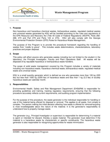
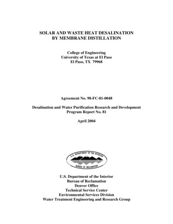
The membrane itself is hydrophobic with pore sizes usually in the range of 0.05 to 0.2 µm—thesame range as microfiltration. Lawson (1995), for example, used polypropylene membraneswith maximum pore sizes ranging from 0.3 to 1.1 µm. Water is kept from penetrating the poresby surface tension and capillary pressure.Membrane distillation has been investigated in very small-scale (a few cm2 of membrane area)laboratory systems, but not on actual operating systems. The goal of this research was to test asmall, commercially available MD module to gather data on flux, thermal efficiency, fouling,distillate quality, and operational characteristics.1.2Experimental SetupThe project was a collaboration with the Swedish firm SCARAB HVR http://www.hvr.se .SCARAB builds air-gap MD systems. An entire system (membrane module plus controllingpumps and heaters) built by SCARAB and previously tested at Sandia National Laboratory wasobtained. (Robert Donovan, personal communication. A copy of Sandia’s test results can beobtained by contacting Mr. Donovan at Sandia.) Preliminary testing was performed with theSandia system, allowing operational experience to be gained while not risking damage to thenew membrane module. The new membrane module was later plumbed and used to collect alldata shown. Heating and cooling water were obtained from the El Paso solar pond.An overall flow schematic is shown in figure 2. Hot brine was pumped from the bottom of thesolar pond and passed through a heat exchanger to supply heat. Cold water from the solar pondsurface was passed through a heat exchanger to provide cooling. High and low temperatures forsystem operation were obtained by changing the flow rates for solar pond hot and cold water.Hot water lines were made of CPVC, and cooling lines were made of PVC. Figure 3 is a pictureof the modified SCARAB system. The membrane module is in the background; 2.94 m2 ofmembrane are present in the module.A series of thermocouple sensors and magnetic flowmeters was installed throughout the systemon the heat exchangers, feed and return lines to the membrane, and in the recirculating coolingloop. Conductivity probes were installed in the make up water tank and in the distillate productline, in order to measure the source water to be tested and the quality of the distillate. All of thementioned sensors and probes were connected to two signal acquisition boards (DBK Omega series), which then were hooked to a computer via a data acquisition board (Daqboard fromOmega ). By using the latest version of the software DaqView , data for temperature, flow,and conductivity were registered for later analysis. Details of the experimental setup are given inSolis (1999).3
Symbols:Hot brineto Solar PondHot brinef/Solar PondTPP- PumpF- Flow MeterT- Analog thermometer- Pressure t Water FeedProductWaterFigure 2. Flow schematic.Figure 3. Modified SCARAB membrane distillation system.4SolarCoolingSourcePond
1.3Experimental PlanThe major purpose of the test matrix was to: (a) determine performance over this range ofoperational parameters; and (b) attempt to deduce controlling factors based upon experimentalresults. The secondary goal was to evaluate membrane fouling during desalination of localwaters.In September 1999, a sequential concentration test was performed using local ground water.Concentrate was recycled back into the source water tank to give sequentially more concentratedfeed. This testing was part of the initial system shakedown.During October and November 1999, an experimental matrix was performed with sodiumchloride solutions. The data collected during these tests are presented in Appendices A throughD at the back of this report. Flux and distillate quality were measured with varying input watersalinity, hot side temperature, and temperature drop. Water properties for the test matrix aregiven in table 1.Table 1. Properties of water tested in experimental matrixNaCl concentrationSpecific gravity(%)Salt content(molality)at 20 Csalinity(g/l)01.0000.00.00.6 11816178.64.01.17123269.6Constant composition during each set of experiments was maintained by returning the distillateto the source tank. Hot side temperature and temperature drop could only be approximatelycontrolled.No pretreatment was provided for the water. Flows and temperatures were recorded directly bycomputer. During evaluation of the experimental matrix, distillate production was measured byhand into a volumetric flask. This was required because the automated flow measurementsystem was not sufficiently accurate at low flow rates.5
2.0 Conclusions and Recommendations2.16Conclusions Flux per unit area of membrane surface ranges from 0 to 6 L/m2/hr. Flux increaseslinearly with transmembrane temperature drop, decreases significantly with increasingsalinity for brines, and depends only weakly on hot side temperature. The data indicate that flux is heat transfer limited and only weakly responsive to vaporpressure gradients between the feed water and cooling water. This is a surprisingconclusion for air gap membrane distillation where diffusional mass transport of watervapor across the membrane and air gap is anticipated to control flux. Flux was measured down to hot side temperatures as low as 13 ºC. Flux per unittemperature drop at very low temperatures was only reduced about 50 percent comparedto flux at higher temperatures. Operation of MD at such low temperatures may open upthermal energy resources that have not previously been considered for desalination. The low dependence of flux on hot side temperature and continuation of flux at very lowtemperatures mean that the technology can take advantage of low-grade heat energy. Very high quality distillate can be produced even from nearly saturated NaCl brine.Distillate quality is primarily dependent upon the degree of wetting of the membrane.Pressure spikes or lack of temperature gradient can lead to wetting of some pores andsubsequent decline in distillate quality. The hydrophobic properties of the membrane can be restored by simple drying. Anordinary hair dryer was used periodically for this purpose. The fraction of the heat supplied that went into distillation ranged from over 90 percentfor low salinity water to around 50 percent for concentrated brine. The membranemodule tested was not designed to recover latent heat. This is not a limitation of thetechnology but, rather, a limitation of current production modules. Theoretical calculations, based upon measured results, indicate that membrane distillationwith latent heat recovery can be easily implemented and that this modification wouldmake MD competitive with other thermal technologies in terms of energy use.
2.2Recommendations Leakage rate through wetted pores is proportional to pressure drop. If the hot waterpassing through the membrane module were kept near atmospheric pressure, the rate ofleakage through wetted pores would be reduced to near zero. This would ensure highdistillate quality even when water begins to penetrate the membrane pores. Damaging pressure spikes could be eliminated by changing the overall system to providegravity flow (high tank to low tank) through the membrane module. A countercurrent flow system would provide greater energy efficiency at the cost oflower flux per unit area of membrane (i.e., higher capital costs). In the short term, the greatest promise for MD is for isolated low technology (village)applications, ships, and the military. Membrane distillation may also be competitive in treating reverse osmosis (ornanofiltration) concentrate. Longer-term tests are required to quantify fouling. No membrane fouling was detectedduring the tests performed on sodium chloride solutions and concentrated local groundwaters. Alternative sources of low-grade thermal energy should be considered for use withMD desalination, such as wet bulb/dry bulb temperature differences, thermally stratifiedwaters, and ground/air temperature differences.7
3.0 Results3.1FluxIn order to better understand the relative role of salt content, hot side temperature, andtemperature drop, initial tests were performed using previously distilled water as the raw watersupply. Flux results for distillation of essentially pure water are shown in figure 4. The differentsymbols represent different ranges of hot side temperatures. The setup of the system precludedvery precise temperature control, making it necessary to lump the data into ranges. In theseexperiments, the flow rate of recirculating water was nominally held at 20 L/min. Flux increaseslinearly with hot to cold side temperature drop and increases only weakly with higher hot sidetemperatures. Visual extrapolation of the data at the low end indicates that flux begins as soon asan infinitesimal temperature drop is created. Comparison of fluxes is only available in thepublished literature from small laboratory systems using a few cm2 of membrane area. Godino,et al. (1996), obtained fluxes up to 12 L/m2/hr in a laboratory direct contact MD test with atemperature drop of 50 ºC. Lawson (1996) obtained up to 68 L/m2/hr in a laboratory directcontact membrane distillation test when the temperature drop was 40 ºC. Lawson used new,higher flux membranes from 3M Company, as well as an experimental apparatus with highReynolds numbers (less temperature polarization). Ohta, et al. (1991), obtained fluxes of up to5.5 L/m2/hr with a direct contact laboratory system. Direct contact systems should have a higherflux and lower thermal efficiency relative to air gap systems.5.0High 60'sFlux (L/m2/hr)4.0High 50'sHigh 45.0Temperature Drop ( C)Figure 4. Production as a function of hot side temperatureand temperature drop for pure water.Flux at 0.6 M input water NaCl concentration (nominally seawater strength), as shown infigure 5, exhibits the same trends. The major differences are: (a) slightly lower flux at anypoint; and (b) initiation of flux requires at least 2 to 3 ºC temperature drop.8
6.070's60's50's40'sFlux 0.035.040.045.0Temperature Drop ( C)Figure 5. Production as a function of hot side temperatureand temperature drop for 0.6 molar waterFigure 6 gives flux at 0, 0.6, 2, and 4 input water NaCl molality for hot side temperaturesbetween 60 and 70 ºC. Flux declines markedly at very high brine concentrations. Thetemperature drop required to initiate flux (i.e., the x-axis intercept) also increases with brinecontent of the source water.7.0M 0M 0.6M 2.0M 4.06.0Flux (L/m2/hr)5.04.03.02.01.00.05.010.015.020.025.0 30.035.040.0 45.0 50.0Temperature Drop ( C)Figure 6. Flux at 50 to 60 C hot side temperature as a function of molality.9
Figure 7 illustrates the influence of the flow rate of the hot side recirculating water. Higher flowrates create greater turbulence (higher Reynolds numbers), which leads to greater heat transfer.Higher water flow rate has a small but significant influence on flux, especially at higher fluxrates associated with high temperature drops.7.06.0Flux 35.040.045.0Temperature Drop ( C)Figure 7. Influence of recirculating water flow rate.An important question is how the system performs at low temperatures. In the above fluxgraphs, the hot side temperatures were held approximately constant while the cold sidetemperature was varied. In order to investigate low temperature performance, this procedure wasreversed: the cold side temperature was held approximately constant while the hot sidetemperature was lowered from 36.5 ºC down to 12.9 ºC. The low temperature results arecompared with higher temperature results in figure 8. At a hot side temperature of 12.9 ºC and atemperature drop of only 1.5 ºC, a measurable flux of 0.08 L/m2/hr was measured. Comparisonof the trendlines demonstrates that hot side temperatures in the range of 13 to 36 ºC produceabout half the flux of hot side temperatures in the range of 60 to 70 ºC at the same temperaturedrop.3.2EnergyEnergy performance is shown in figure 9. The economy ratio is defined as the ratio of the heatenergy theoretically required to distill the measured flux of water divided by the total heat energyused by the system. The economy ratio was calculated only for the highest temperature dropswhere flux was greatest. The system design has high flow rates of hot and cold water passingthrough the module, with small temperature changes between input and output flows. For thisreason, a high uncertainty is associated with the measured energy balance, especially at lowerflux rates.10
76Flux (L/m2/hr)5y 0.1257x432y 0.0584x1051015202530354045Temperature Drop ( C)High 60'sHigh 13-36Linear (High 60's)Linear (High 13-36)Figure 8. Comparison of performance at low temperatures.Figure 9. Economy ratio as influenced by molality.Figure 9 shows decreasing energy efficiency as the brine becomes more concentrated. Themembrane module tested was not designed to recover latent heat and should have a theoreticalmaximum economy ratio of one. We have been unable to find any published, measured,11
energy efficiency data for membrane distillation. Based upon first principles, air gap membranedistillation should be more energetically efficient than direct contact membrane distillation.Although fluxes are lower (meaning capital costs would increase), MD can be used to desalinatewater at very low hot side temperatures (down to at least 13 ºC).3.3Quality - Wetting of the MembraneThe hydrophobic nature of the membrane separates the brackish, warm water from the air gap.For simplicity, only one pore is shown in the hydrophobic membrane in figure 10. The water"bulges" through the pore until the surface tension and radius of curvature create a force toexactly balance the pressure drop across the membrane. This force per unit area, which is equalto the pressure drop across the membrane, is called the capillary pressure.Figure 10. Capillary pressure.The maximum radius of curvature and, thus, maximum capillary pressure prior to leakage ofliquid water across the membrane depend upon pore size and surface tension. When the surfacetension forces are overwhelmed, the pore begins leaking. Once a pore begins leaking, themembrane may locally lose its hydrophobic properties, leading to constant leaking at anywater/air pressure differential (Banat, et al., 1994). Surface tension and viscosity of waterdecline with temperature (Chemical Rubber Company, 1970), making leakage a greater potentialproblem at higher temperatures.Portions of the membrane that become wet leak, based upon the total pressure drop across themembrane. For experiments where the water recirculating flow rate was not changed, the rate ofleakage was approximately constant. As the flux increases, the leaking water is diluted bydistillate, which leads to better water quality. An example is shown in figure 11. The rate of12
leakage through the membrane can be calculated from the conductivity of the source and distilledwater. All reported fluxes in this report were corrected for membrane leakage rates.35.0Flux (L/m 2/hr)Prod Conductivity (µS/cm)Flux or 0.025.035.030.040.045.0Temperature Drop ( C)Figure 11. Quality as influenced by flux.The history of membrane leakage is plotted in figure 12. The bars give calculated leakage rate,and the salinity of the source water being tested is shown by the line. The input lines to themembrane module were periodically disconnected, and an ordinary hair dryer was placed at theinput line to dry the membrane. When leakage rates were high, drying of the membrane greatlylowered leakage rates.1.006.000.90molality of source 9910/05/990.009/23/990.100.00DateFigure 12. History of membrane leakage.13
Figure 13 shows the results for the groundwater tests performed during September. The sourcewater was sequentially concentrated by recycling concentrate into the source tank. Figure 14 isthe percent removal of dissolved solids during the tests. The only low percent removal occurredduring a day when the temperature drop was reduced to 1.3 ºC. As explained above, at low fluxthe distillate production declines, while leakage of source water across wetted pores remainsconstant, leading to net decline in output water quality. Overall, removal efficiency is very highand independent of the concentration of the source water. Although there was no evidence ofmembrane foul
solar pond and passed through a heat exchanger to supply heat. Cold water from the solar pond surface was passed through a heat exchanger to provide cooling. High and low temperatures for system operation were obtained by changing the flow rates for solar pond hot and cold water. Hot water lines were made of CPVC, and cooling lines were made of .