Transcription
ABB drivesTechnical guide No. 9Guide to motion control drives
2 Motion control Technical guide No. 9
Technical guide No. 9Guide to motion control drives Copyright 2013 ABB. All rights reserved.Specifications subject to change without notice.3AFE68695201 REV B EN 11.2.2013Technical guide No. 9 Motion control 3
4 Motion control Technical guide No. 9
ContentsChapter 1 - Introduction .71.1.1.2.1.3.1.4.1.5.Motion control versus speed control .7Decentralized or centralized control .8Comparison between decentralized and centralized systems .9Main functional parts of machine .9Machine components .10Chapter 2 - Drive and motor combination .112.1.2.2.2.3.2.4.Brush-type DC .11Brushless DC .11Asynchronous servo .12Synchronous servo .13Chapter 3 - Synchronous technology .143.1. Measuring performance .143.2. How synchronous servo motors differ from induction motors .15Chapter 4 - Synchronous servo motor – principle of operation .164.1. Special conditions during startup .174.2. Traditional speed and current control .17Chapter 5 - Typical servo motors data.195.1.5.2.5.3.5.4.Torque constant.19Back EMF .19Torque curve .19Typical motor data .20Chapter 6 - Feedback devices .216.1. Resolver .216.2. Incremental encoders .226.3. SinCos encoder .22Chapter 7 - Motion control .247.1.7.2.7.3.7.4.7.5.General .24Motion control – basic blocks .24Motion control formulas and profiles .25Motion profile .25Position interpolator .25Technical guide No. 9 Motion control 5
Chapter 8 - Typical motion functions .268.1. Positioning .268.2. Absolute positioning .268.3. Relative positioning .268.4. Synchronization .278.5. Rollover axis .288.6. Dynamic limiter .288.7. CAM disk .288.8. Homing .298.9. Cyclic corrections .318.10. Encoder gear functions .328.11. Virtual master/axis .33Chapter 9 - Application examples, distributed control .349.1. Cyclic correction for material handling. .349.2. Constant gap maintaining .359.3. Cut to length .369.4. Rotary knife .379.5. Cyclic correction, packing application .389.6. Flying shear, angled .399.7. Flying shear, parallel .409.8. Lathe .419.9. Material filling .429.10. Slitter .439.11. Picking and stacking .449.12. Warehouse automation .459.13. Winding .469.14. Wrapping .47Chapter 10 - Motion control – *Glossary of terms .48Chapter 11 - Index .626 Motion control Technical guide No. 9
Chapter 1 - IntroductionThis guide aims to give users an overview of high performancedrives and motion control. Although written in a simple style tomake it relevant to most applications, readers need to have abasic understanding of AC drive technology to benefit from thisguide.When considering a motion control application it is importantto consider all elements in the system including drives, motors,mechanical power transmission components, software, etc.A high performance system has one or more of the followingcharacteristics:––––high dynamic performancehigh accuracy reference following and repeatabilityhigh accuracy motion functionscapability to run different motor types1.1. Motion control versus speed controlStandard variable speed drives normally control the motor bygiving a speed command. The system typically has no feedbackand speed reference is preset speeds, 0 to 10 Volts, 4 to 20 mA,or fieldbus.With motion control, there is always feedback of the real position.This is compared to the reference value and the difference is corrected continuously by the motion controller’s profile generator.Positioning is a good example that highlights this difference. If astandard drive is used for positioning, the motor normally runsat high speed, then decelerates to a lower speed and stops.Alternatively, the drive can follow an analog signal. Either way, noreference profile is followed, compared for errors or corrected.This results in low accuracy.Accuracy can be improved if the controller is a high performance motion controller but in this case, the dynamics and thesample time (generally several milliseconds) of the standard drivebecome limiting factors.Technical guide No. 9 Motion control 7
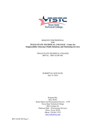
Introduction1.2. Decentralized or centralized controlIn a system with centralized control, one unit contains all thesoftware and the drives just follow the reference value. There isno intelligence within the drive.Motion controllerSpeedreferenceFigure 1.1 Simplified centralized system.In a decentralized system, the field devices also have intelligence.This means that the cost of the control unit is reduced, as farless performance is required centrally.Higher level commandsI/OFigure 1.2 Simplified decentralized system.8 Motion control Technical guide No. 9
Introduction1.3. Comparison between decentralized and centralized systemsFeatureDecentralizedCentralizedBenefits ofdecentralizedcontrolNumber of controlwiresLowHighLess cabling– lower costFewer potentialfaults wiresCabinetLess components,smaller sizeMore componentsinstalledLabour and materialcost savingProgrammableLogic Controller(PLC)Control distributedAll control,additional hardwarecostCost saving in PLChardwareTime levelsMotion loop isclosed in drive *Motion loop isclosed in controllerGood cost/performance ratioDrive-to-drivecommunicationFast t usedLess hardware*This means that feedback is connected directly to drive. It doesnot go to PLC or motion controller for calculation which mightcause delay.More detailed information of motion control in chapter 7.1.4. Main functional parts of machineMachines using motion control and/or high performance drivesconsist of the following, all of which have a deciding influenceon the performance of the system:– Motion control hardware: this controls the operation of thesystem; it can be centralized or decentralized– Motion control software: determines the functions of themachine by receiving input data and handling this accordingto the instructions set out in the software code– Drive or amplifier – receives commands from the motioncontrol software– Motor – provides mechanical energy with the required speedand torque to drive the load in the specified way– Mechanical power transmission components – belts, gearboxes, clutches, ballscrews etc.Technical guide No. 9 Motion control 9
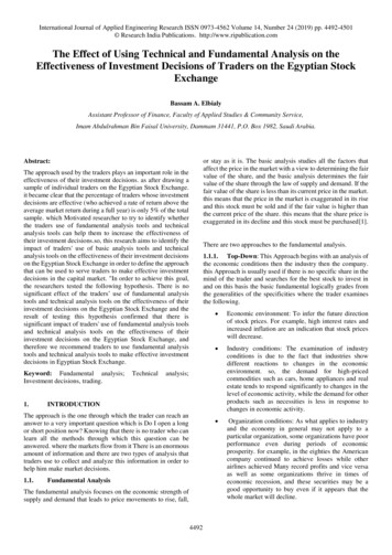
IntroductionFollower driveUpper controlsystem (PLC)Master driveEncoder option moduleI/O option moduleI/O extensionMotorcableFieldbusFieldbus option moduleEncoder option moduleDrive-to-drive linkMaster/followerFibres Hard wired probefor standard I/OMotor cableSynchronous motor encoderMaster encoderFigure 1.3 Constant gap maintaining.1.5. Machine componentsFigure 1.3 shows a basic setup. The distance between boxes onthe conveyor belt varies and the purpose of the motion controlsoftware is to accelerate or decelerate the belt and space theboxes equally.Main components:– Drives and cables (power, feedback, control)– Overriding control by PLC– Motor encoder monitoring closed loop motor control andposition information for cyclic correction– Master encoder, giving speed reference of production line– Fibre optic cable for communication between drives– Fieldbus, encoder and drive-to-drive link– Sensor giving 24 V on/off information to drive– Synchronous encoder10 Motion control Technical guide No. 9
Chapter 2 - Drive and motor combinationThe drive and motor are normally supplied as a package to suitthe application. The main drive, motor types and features aredescribed here.2.1. Brush-type DCThe basic principle is the same as in industrial high power DCdrives, the main difference being that there is no magnetizingcircuit. Instead, the motor carries permanent magnets on thestator side. Rotor current and voltage is supplied by brushesand a commutator.Normally, it is not possible to use the supply voltage. Instead,a transformer is used to reduce the voltage. Some drives havea rectifier circuit, while others need an external voltage rectifier.The electronics are relatively simple and only speed feedback isrequired for the speed controller. Brush-type DC drives is oneof a small number of control platforms that actually use a tachoas a feedback device for the speed reference.When this type of drive and motor combination is used in motion control, a pulse encoder is quite often fitted to the motorshaft. Pulses are sent to the motion controller for calculatingthe position.The benefit of brush-type technology is the simple and inexpensive controller. The drawback is that the commutator and thebrushes are mechanical components and have limited lifetime.Especially in applications where the motor always stops in thesame position, the commutator gets worn in one particular place,thereby reducing its life even more.The main players in the drives industry do not use this technology anymore. Typically these kinds of products are based onold analogue platform.2.2. Brushless DCThe power circuit of a brushless DC servo drive is similar to thatof an AC drive. Input current is rectified and filtered in a diodebridge with associated DC-link capacitance. The inverter unitconsists of six power devices.However, with a brushless DC drive the output voltage is notmodulated to form sinusoidal current, unlike in an AC drive.Technical guide No. 9 Motion control 11
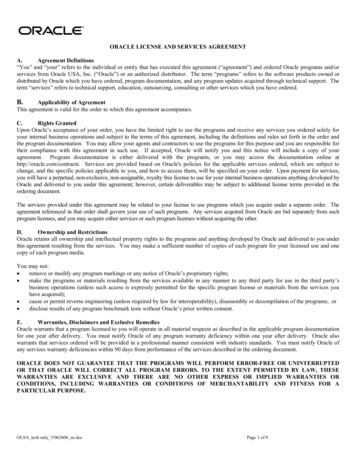
Drive and motor combinationInstead, six possible switching combinations are used to forma trapezoidal vector diagram. Typically, hall sensors (hall sensoris a device that senses magnetic field are used to identify rotorposition) and a tacho generator gives feedback to the speedcontroller.Figure 2.1 Rotational voltage vectors in trapezoidal control.In the AC drive, the motor’s back EMF (electro magnetic force)tends to be sinusoidal, while brushless DC servo motors havea trapezoidal back EMF.The brushless DC servo control algorithm does not need as muchcomputing power as a sinusoidal drive. The tacho also providesfast input to the speed controller.However, with faster, more powerful and reasonably pricedprocessors, very high performance drives with sinusoidal outputhas been developed.The main problem with trapezoidal control is torque ripple, especially at low speeds. There are ways to improve the performance but it seems that this technology is disappearing from themain marketplace.2.3. Asynchronous servoThe amount of slip forces current to the rotor determines thetorque. This motor type has a light and small diameter rotor tominimize inertia. This means that the inertia, which is inverselyproportional to acceleration, is lower than in induction motors,although it is higher than in permanent magnet servo motors.Suitable control methods are closed loop vector or DTC control.This method gives performance equal to that of drives with asynchronous servo motors. The main limiting factor is the motor.This drive can often be referred to as a servo drive, due to thenature of the motor or a closed loop control for standard ACinduction motors.However, feedback from an incremental encoder, resolver orSinCos encoder is always needed.12 Motion control Technical guide No. 9
Drive and motor combination2.4. Synchronous servoThis type of motor is quite often called AC brushless servo. Synchronous servo motors have a rotor with permanent magnetsand a stator for three phase supply. The rotor has very low inertiaand can achieve fast dynamic performance. The motor operationis synchronous and the feedback device has to be able to delivercontinuous position and speed information to the amplifier.In chapter 3 (page 15) the AC synchronous servo motor is explained in more detailes.Technical guide No. 9 Motion control 13
Chapter 3 - Synchronous technologyThe drive or amplifier delivers a sinusoidal output modulatedfrom the DC-link voltage (traditional modulator or an advancedmethod like DTC). This makes the power circuit identical to thatof a conventional drive. Using permanent magnet motors, thebasic algorithm only needs to produce current for the torque - nomagnetizing current is needed.Servo motors, like induction motors, are manufactured with different numbers of poles. Taking a 6-pole motor as an example,the name plate states 940 rpm nominal speed (standard induction) and therefore the synchronous speed is 1000 rpm. This isachieved at 50 Hz input frequency and at higher speeds, themotor operates in its field weakening area. This is slightly simplified because some asynchronous servo motors are designed torun at other than 50 Hz field weakening point.Synchronous motors use sinusoidal wave form and constanttorque up to nominal speed but in such a way that the frequencyat nominal speed is, for example, 150 Hz for the motor at 3000rpm nominal speed (six pole winding).3.1. Measuring performanceThe key performance indicator is the bandwidth of differentcontrol loops.Typical good speed control loop has bandwidth of 100 Hz andtorque loop has 800 Hz.Increasing the frequency means that the amplifier tends to looseits ability to respond. Normally, the bandwidth is measured upto a level where the output is 3 db less than the reference level.Bandwidth of a signal is a measure of how rapidly it fluctuateswith respect to time. Hence, the greater the bandwidth, the fasterthe variation in the signal may be.Figure 3.1 Amplifier’s response variation as a function of frequency.14 Motion control Technical guide No. 9
AC brushless technologyThe other problem is phase delay in the amplifier circuit. As thefrequency increases, the amplifiers tend to loose the originalphase.Figure 3.2 Amplifier’s phase delay as a function of frequency.3.2. How synchronous servo motors differ from induction motorsThe main difference between synchronous servo motors andinduction motors is in the motor shaft performance. With synchronous servo motors, rotor mass and diameter are minimized,leading to low inertia which in turn means the rotor does notneed much torque to accelerate. Most of the torque producedcan be used to run the load.Typical features of synchronous servo motors:– The motor efficiency is typically over 95% at full power.– The motor has high power density – there is no rotor currentand thus no build-up of heat in the rotor.– The motors can run with high temperature rise, for example,at 40 degrees ambient, temperature rise/class H 125 Cis allowed.– IP65 is the typical protection degree, compared to IP54 forstandard induction motors.– Standard AC induction motors are inexpensive. But for higherperformance, additional feedback devices are needed andthese can be costly.– Other costs include encoders, fans making asynchronousservo motor a more attractive choice.– High torque overload capability depends on the basic motordesign and its magnetic materials. Generally, synchronousservo motor motors can deliver up to 2-5 times or moreoverload during short periods.– Resolver, incremental encoder with commutation channels orvarious types of SinCos encoders can be used as feedbackdevices. Full digital feedback systems are also available.– Recent development of drives and motion control systems,along with lower cost magnetic materials, has increased themarket and number of applications for synchronous servomotor rapidly.Technical guide No. 9 Motion control 15
Chapter 4 - Synchronous servo motor –principle of operationThe synchronous servo motor does not have commutator orbrushes. The drive (amplifier) maintains correct current distribution at the right vector angles and the right angular speed.The rotor of synchronous servo motor is not symmetrical but hasa magnetic polarity. The stator provides the three-phase sinusoidal current. The stator current forms the composite flux vector.U phaseV phaseW phaseFigure 4.1 Magnetic fields at two positions.The flux produced by permanent magnets and the flux producedby stator currents must be at exact opposites to maximize therepulsive and attractive forces of the magnetic fields.These are the forces that build up torque and cause the motorshaft to rotate. This operation needs a feedback device thatsenses angular position of the shaft at all times, enabling theamplifier to setup sine output to the right angles.16 Motion control Technical guide No. 9
Synchronous servo motor – principle of operation4.1. Special conditions during startupNew motors can sometimes have a difference between the actual rotor position and that given by the feedback device. Thisneeds to be corrected, otherwise inaccurate feedback resultsin the motor not being able to produce full torque and optimumperformance.The phase error can be resolved in different ways:Initial startup:– The drive features phasing error software which identifiesthe error during the commissioning run and uses its controlalgorithm to compensate for the error– Error information from the motor manufacturer is entered asa parameter into the drive. This becomes important if a sparemotor is installed and a non-load trial run is difficult to perform– Some motor producers build in zero phase error duringmanufacture – this is the preferred option as it avoids theabove tasksStartup after power down:– When powering up, the rotor position is known if the feedback device (such as resolvers and some SinCos encoderswith communication bus) can give absolute position withinone revolution.– However, if an incremental encoder is used, then commutationchannels are required. At startup, the motor is controlled inthe trapezoidal manner, as long as the position is identifiedusing the commutation signals. See also chapter 6, page 21for feedback devices.4.2. Traditional speed and current controlFigure 4.2 shows the basic principle of speed and currentcontrol.PID speedcontrollerCurrent ref.to motorPI currentcontrollerSpeedreferenceInverterCurrent measurementfeedbackFigure 4.2 Speed and current control loop.Technical guide No. 9 Motion control 17
Synchronous servo motor – principle of operationThe role of the servo drive or amplifier is to make sure that themotor speed and torque follows the reference value. The motor sfeedback gives actual speed to the speed controller. The speedcontroller is typically a PID controller comparing reference andfeedback signals.The error signal is passed to the current controller. The currentcontroller, typically a PI amplifier, sets up the correct current sothat the right torque is available to keep the speed at the reference level.18 Motion control Technical guide No. 9
Chapter 5 - Typical servo motors data5.1. Torque constantThe torque constant is an important measure given to the synchronous servo motor. It is expressed as Nm/A and determineshow much torque is produced per ampere.5.2. Back EMFThe permanent magnet motor acts like generator and builds upback EMF voltage which is related to angular speed. Back EMFis opposite to the supply voltage and is in direct relation to theangular speed.Ke is voltage constant and is typically expressed in V/1000 rpm(voltage rms value).5.3. Torque curveTorque (Nm)Short term overload areaContinous torqueSpeed (rpm)Figure 5.1 Torque curves of a synchronous servo motor.The picture shows a typical torque curve of an synchronous servomotor. It consists of a continuous torque curve and a short termoverload curve. Typical values given as part of the motor data are:– T stall which is nominal torque at zero speed– T nominal which is nominal torque at nominal speed– T peak which is maximum torque which is typically 2 to 5times nominal torque.Synchronous servo motors are normally selected so that the highest running speed is close to the nominal speed. One importantlimiting factor is back EMF.Technical guide No. 9 Motion control 19
Typical servo motors dataWhen the speed increases, the back EMF increases. This meansthere is a limit where the back EMF would be equal to or higherthan the drive’s maximum output voltage.Synchronous servo motors normally run at a voltage which is farlower than the drive’s maximum output voltage. For example,560 V may be used for the DC link drive and 300 V nominal forthe motor. The reason is that the motor has to be able to recoverfrom peak loads very quickly.On the other hand there are technical solutions that make itpossible to run synchronous motors in field weakening area.This means that motor needs more current to the motor windings. This is achieved by increasing the voltage and thus theremust be margin between nominal and maximum voltage. This isalso the reason why maximum torque output starts to decreasewhen the speed becomes closer to nominal speed.Synchronous servo motors do not typically have cooling fan.Some suppliers offer cooling fans as option. It increases thenominal and thus RMS torque, but not peak torque.5.4. Typical motor dataThis is a summary of typical nominal values and other motor data. Thereference values are for ABB Servomotors series .3TypeTorqueconstantKt0[Nm/A](1) (2) (3)8C1.1.301.05Current atcontinuoustorqueI0[A](1) (2) (3)RatedtorqueMN[Nm](3)2.11.2B.e.m.f. betweenphases at ratedspeedV[V](1) (2) (3)190RatedRatedcurrentspeedINnN[A][revi/min](1) (2) (3)2ResistanceatterminalsRUV[W](1) (3)20.820 Motion control Technical guide No. tat 4.68.113.8Moment ofinertia of 000InductanceatterminalsLUV[mH](4)47
Chapter 6 - Feedback devicesHigh performance drives often use rotational feedback devicesto give:–––––speed feedback to the amplifier’s speed controllerposition information to internal/external position controlshaft position to the amplifierposition information when acting as second encoderabsolute position after black out6.1. ResolverA resolver is a rotational transformer. The most common type isa brushless resolver.The resolver has a three coil arrangement. The reference signal,for instance an 8 kHz sine wave, is connected to the rotatingpart of the device via a transformer. This enables the coil carryingreference to rotate at the same speed as the shaft.Two other coils are placed in 90 degrees phase shift. The rotational coil induces voltage in these coils. Output signals are fedto the amplifier and the speed and the position of the rotor isresolved by using these signals.Frequently, resolver signals are converted to a pulse train foran external motion controller. In other words there is outputthat emulates encoder channels A, B and Z pulses. Read alsoencoder information.Cos windingS4Vc Vr Cos (θ)S2SinwindingR1VrS3Vs Vr Sin (θ)S1R2RotarytransformerFigure 6.1 The principle of a resolver.Technical guide No. 9 Motion control 21
Feedback devices6.2. Incremental encodersIncremental encoders are widely used in various machine building applications.The basic operation is based on a light source, a disk and a photocell (sensor). The disk is installed between the light source andthe sensor. The disk has a very fine mesh, enabling light to bevisible or obscured to the sensor. The sensor output is digitizedto form a square pulse when light is seen. When the disk rotates,the sensor produces a pulse train. The frequency of the pulsetrain is in relation to the speed of the axis and the receiving endcan calculate this.There are various specifications for encoders, but for motioncontrol, two channels plus a zero channel is the most commonlyused. Each channel is typically differential so that the output isA, A inversion, B, B inversion and Z, Z inversion.X2SHSHA AB BZ Z-Differential encoderOutput voltageselection withjumperPulse order in forwardrotation: A-pulse firstA AB B-X10V0 VV out 15 VV in 24 VForward rotation clockwisefrom the shaft endInternal connection in theoption moduleFigure 6.2 Typical circuits and cables6.3. SinCos encoderThe SinCos encoder operates in a similar way to the incrementalencoder. It typically has three channels, A, B and Z. While theoutput from an incremental encoder is a digitized square wave,the SinCos encoder output is a number representing the full sineand cosine waves. The number of cycles can be, for example,1024 full cycles, often also called “increments”. The receivingcircuit of the drive calculates the increments and interpolatesbetween these signals to improve the resolution. The interpolation depends on the sample time of the drive. For example, ifthe sample time is 250 us, a sample of sinus and cosine is takenevery 250 us; the lower the speed, the higher resolution can beachieved (and visa versa). From a mathematical point of view,the angle is arctan (sinα/cosα).22 Motion control Technical guide No. 9
Feedback devicesTypically, the drive hardware outputs a quadrate signal of sine/cosine signals, so that what is seen is a pulse train input forcalculation. The rising and falling edges of both channels can beutilized, giving four signals per cycle. This results in a number ofsignals that is four times higher than the number cycles specifiedin the encoder data.SINEcommutation trackCOSINEcommutation trackSINE & COSINE incremental tracksZ-marker pulseZ-marker pulseFigure 6.3 Output of SinCos encoder with commutation channel.The absolute position of the rotor is also needed at startup. Thiscan be established by using a data link (next chapter) or by anadditional sine/cosine channel. This channel provides one fullsine and cosine cycle per revolution and makes it possible tofind the rotor position. The Z-pulse position can be checked byensuring that the Z pulse is “high” when the sine/cosine channels show zero position.angle tan-1pulse 256xypulse 2570,351 Figure 6.4 Interpolation within one cycle in SinCos encoder (1024 cyclesper revolution)SinCos encoders are also available with data bus. A data bus cangive absolute position after power-down, a common requirementin today’s applications. This eliminates the need for homing routines after power-down. This makes the machine design simplerand increases the machine’s production time. Data of absoluteposition is also used at startup to identify the rotor position.Technical guide No. 9 Motion control 23
Chapter 7 - Motion control7.1. GeneralMotion control covers many different functions. This chapterdeals with basics of speed and motion and functional differences.7.2. Motion control – basic blocksSp
- Motion control hardware: this controls the operation of the system; it can be centralized or decentralized - Motion control software: determines the functions of the machine by receiving input data and handling this according to the instructions set out in the software code - Drive or amplifier - receives commands from the motion