Transcription
11Boeing B-777: Fly-ByWire Flight ControlsGregg F. BartleyBoeing11.111.211.311.4IntroductionSystem OverviewDesign PhilosophySystem ArchitectureFlight Deck Controls System Electronics ARINC 629Data Bus Interface to Other AirplaneSystems Electrical Power11.5Control Surface ActuationFly-by-Wire Actuation Mechanical Control11.611.711.8Fault ToleranceSystem Operating ModesControl Laws and System FunctionalityPitch Control Yaw Control Roll Control 757 TestBed Actuator Force-Flight Elimination11.911.10Primary Flight Controls System Displaysand AnnunciationsSystem MaintenanceCentral Maintenance Computer Line ReplaceableUnits Component Adjustment11.11 SummaryDefining Terms11.1 IntroductionFly-By-Wire (FBW) Primary Flight Controls have been been used in military applications such asfighter airplanes for a number of years. It has been a rather recent development to employ them in acommercial transport application. The 777 is the first commercial transport manufactured by Boeingwhich employees a FBW Primary Flight Control System. This chapter will examine a FBW PrimaryFlight Control System using the specific system on the 777 as an example. It must be kept in mindwhile reading this chapter that this is only a single example of what is currently in service in the airlineindustry. There are several other airplanes in commercial service made by other manufacturers thatemploy a different architecture for their FBW flight control system than described here.A FBW flight control system has several advantages over a mechanical system. These include: Overall reduction in airframe weight.Integration of several federated systems into a single system.Superior airplane handling characteristics.Ease of maintenance. 2001 by CRC Press LLC
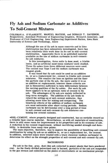
Ease of manufacture. Greater flexibility for including new functionality or changes after initial design and production.11.2 System OverviewConventional primary flight controls systems employ hydraulic actuators and control valves controlledby cables that are driven by the pilot controls. These cables run the length of the airframe from thecockpit area to the surfaces to be controlled. This type of system, while providing full airplane controlover the entire flight regime, does have some distinct drawbacks. The cable-controlled system comes witha weight penalty due to the long cable runs, pulleys, brackets, and supports needed. The system requiresperiodic maintenance, such as lubrication and adjustments due to cable stretch over time. In addition,systems such as the yaw damper that provide enhanced control of the flight control surfaces requirededicated actuation, wiring, and electronic controllers. This adds to the overall system weight andincreases the number of components in the system.FIGURE 11.1 The Primary Flight Control System on the Boeing 777 is comprised of the outboard ailerons,flaperons, elevator, rudder, horizontal stabilizer, and the spoiler/speedbrakes.In a FBW flight control system, the cable control of the primary flight control surfaces has beenremoved. Rather, the actuators are controlled electrically. At the heart of the FBW system are electroniccomputers. These computers convert electrical signals sent from position transducers attached to thepilot controls into commands that are transmitted to the actuators. Because of these changes to thesystem, the following design features have been made possible: Full-time surface control utilizing advanced control laws. The aerodynamic surfaces of the 777have been sized to afford the required airplane response during critical flight conditions. Thereaction time of the control laws is much faster than that of an alert pilot. Therefore, the size ofthe flight control surfaces could be made smaller than those required for a conventionally controlled airplane. This results in an overall reduction in the weight of the system. Retention of the desirable flight control characteristics of a conventionally controlled system andthe removal of the undesirable characteristics. This aspect is discussed further in the section oncontrol laws and system functionality. Integration of functions such as the yaw damper into the basic surface control. This allows theseparate components normally used for these functions to be removed. Improved system reliability and maintainability. 2001 by CRC Press LLC
11.3 Design PhilosophyThe philosophy employed during the design of the 777 Primary Flight Control System maintains asystem operation that is consistent with a pilot’s past training and experience. What is meant by thisis that however different the actual system architecture is from previous Boeing airplanes, the presentation to the pilot is that of a conventionally controlled mechanical system. The 777 retains theconventional control column, wheel, and rudder pedals, whose operation are identical to the controlsemployed on other Boeing transport aircraft. The flight deck controls of the 777 are very similar tothose of the Boeing 747-400, which employs a traditional mechanically controlled Primary Flight ControlSystem.Because the system is controlled electronically, there is an opportunity to include system controlaugmentation and envelope protection features that would have been difficult to provide in a conventionalmechanical system. The 777 Primary Flight Control System has made full use of the capabilities of thisarchitecture by including such features as: Bank angle protectionTurn compensationStall and overspeed protectionPitch control and stability augmentationThrust asymmetry compensationMore will be said of these specific features later. What should be noted, however, is that none of thesefeatures limit the action of the pilot. The 777 design utilizes envelope protection in all of its functionalityrather than envelope limiting. Envelope protection deters pilot inputs from exceeding certain predefinedlimits but does not prohibit it. Envelope limiting prevents the pilot from commanding the airplane beyondset limits. For example, the 777 bank angle protection feature will significantly increase the wheel forcea pilot encounters when attempting to roll the airplane past a predefined bank angle. This acts as aprompt to the pilot that the airplane is approaching the bank angle limit. However, if deemed necessary,the pilot may override this protection by exerting a greater force on the wheel than is being exerted bythe backdrive actuator. The intent is to inform the pilot that the command being given would put theairplane outside of its normal operating envelope, but the ability to do so is not precluded. This conceptis central to the design philosophy of the 777 Primary Flight Control System.11.4 System Architecture11.4.1 Flight Deck ControlsAs noted previously, the 777 flight deck utilizes standard flight deck controls; a control column, wheel,and rudder pedals that are mechanically linked between the Captain’s and First Officer’s controls. Thisprecludes any conflicting input between the Captain and First Officer into the Primary Flight ControlSystem. Instead of the pilot controls driving quadrants and cables, as in a conventional system, they areattached to electrical transducers that convert mechanical displacement into electrical signals.A gradient control actuator is attached to the two control column feel units. These units provide thetactile feel of the control column by proportionally increasing the amount of force the pilot experiencesduring a maneuver with an increase in airspeed. This is consistent with a pilot’s experience in conventionalcommercial jet transports.Additionally, the flight deck controls are fitted with what are referred to as ‘‘backdrive actuators.” Asthe name implies, these actuators backdrive the flight deck controls during autopilot operation. Thisfeature is also consistent with what a pilot is used to in conventionally controlled aircraft and allows thepilot to monitor the operation of the autopilot via immediate visual feedback of the pilot controls thatis easily recognizable. 2001 by CRC Press LLC
11.4.2 System ElectronicsThere are two types of electronic computers used in the 777 Primary Flight Control System: the ActuatorControl Electronics (ACE), which is primarily an analog device, and the Primary Flight Computer (PFC),which utilizes digital technology. There are four ACEs and three PFCs employed in the system. Thefunction of the ACE is to interface with the pilot control transducers and to control the Primary FlightControl System actuation with analog servo loops. The role of the PFC is the calculation of control lawsby converting the pilot control position into actuation commands, which are then transmitted to theACE. The PFC also contains ancillary functions, such as system monitoring, crew annunciation, and allthe Primary Flight Control System onboard maintenance capabilities.Four identical ACEs are used in the system, referred to as L1, L2, C, and R. These designations correspondroughly to the left, center, and right hydraulic systems on the airplane. The flight control functionsare distributed among the four ACEs. The ACEs decode the signals received from the transducers usedon the flight deck controls and the primary surface actuation. The ACEs convert the transducer positioninto a digital value and then transmit that value over the ARINC 629 data busses for use by the PFCs.There are three PFCs in the system, referred to as L, C, and R. The PFCs use these pilot control and surfacepositions to calculate the required surface commands. At this time, the command of the automaticfunctions, such as the yaw damper rudder commands, are summed with the flight deck control commands, and are then transmitted back to the ACEs via the same ARINC 629 data busses. The ACEsthen convert these commands into analog commands for each individual actuator.11.4.3 ARINC 629 Data BusThe ACEs and PFCs communicate with each other, as well as with all other systems on the airplane, viatriplex, bi-directional ARINC 629 Flight Controls data busses, referred to as L, C, and R. The connectionfrom these electronic units to each of the data busses is via a stub cable and an ARINC 629 coupler. Eachcoupler may be removed and replaced without disturbing the integrity of the data bus itself.11.4.4 Interface to Other Airplane SystemsThe Primary Flight Control System transmits and receives data from other airplane systems by twodifferent pathways. The Air Data and Inertial Reference Unit (ADIRU), Standby Attitude and Air DataReference Unit (SAARU), and the Autopilot Flight Director Computers (AFDC) transmit and receivedata on the ARINC 629 flight controls data busses, which is a direct interface to the Primary FlightComputers. Other systems, such as the Flap Slat Electronics Unit (FSEU), Proximity Switch ElectronicsUnit (PSEU), and Engine Data Interface Unit (EDIU) transmit and receive their data on the ARINC 629systems data busses. The PFCs receive data from these systems through the Airplane Information Management System (AIMS) Data Conversion Gateway (DCG) function. The DCG supplies data from thesystems data busses onto the flight controls data busses. This gateway between the two main sets ofARINC 629 busses maintains separation between the critical flight controls busses and the essentialsystems busses but still allows data to be passed back and forth.11.4.5 Electrical PowerThere are three individual power systems dedicated to the Primary Flight Control System, which arecollectively referred to as the Flight Controls Direct Current (FCDC) power system. An FCDC PowerSupply Assembly (PSA) powers each of the three power systems. Two dedicated Permanent MagnetGenerators (PMG) on each engine generate AC power for the FCDC power system. Each PSA convertsthe PMG alternating current into 28 V DC for use by the electronic modules in the Primary Flight ControlSystem. Alternative power sources for the PSAs include the airplane Ram Air Turbine (RAT), the 28-VDC main airplane busses, the airplane hot battery buss, and dedicated 5 Ah FCDC batteries. Duringflight, the PSAs draw power from the PMGs. For on-ground engines-off operation or for in-flight failuresof the PMGs, the PSAs draw power from any available source. 2001 by CRC Press LLC
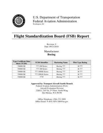
FIGURE 11.2 Block diagram of the electronic components of the 777 Primary Flight Control System, as well asthe interfaces to other airplane systems.11.5 Control Surface Actuation11.5.1 Fly-by-Wire ActuationThe control surfaces on the wing and tail of the 777 are controlled by hydraulically powered,electrically signaled actuators. The elevators, ailerons, and flaperons are controlled by two actuatorsper surface, the rudder is controlled by three. Each spoiler panel is powered by a single actuator.The horizontal stabilizer is positioned by two parallel hydraulic motors driving the stabilizer jackscrew.The actuation powering the elevators, ailerons, flaperons, and rudder have several operational modes.These modes, and the surfaces that each are applicable to, are defined below. 2001 by CRC Press LLC
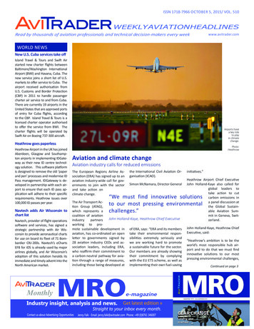
FIGURE 11.3Block diagram of the 777 Fly-By-Wire Power Distribution System.Active—Normally, all the actuators on the elevators, ailerons, flaperons, and rudder receive commandsfrom their respective ACEs and position the surfaces accordingly. The actuators will remain in theactive mode until commanded into another mode by the ACEs.Bypassed—In this mode, the actuator does not respond to commands from its ACE. The actuator isallowed to move freely, so that the redundant actuator(s) on a given surface may position thesurface without any loss of authority, i.e., the actuator in the active mode does not have tooverpower the bypassed actuator. This mode is present on the aileron, flaperon, and rudderactuators.Damped—In this mode, the actuator does not respond to the commands from the ACE. The actuatoris allowed to move, but at a restricted rate which provides flutter damping for that surface. Thismode allows the other actuator(s) on the surface to continue to operate the surface at a ratesufficient for airplane control. This mode is present on elevator and rudder actuators.Blocked—In this mode, the actuator does not respond to commands from the ACE, and it is notallowed to move. When both actuators on a surface (which is controlled by two actuators) havefailed, they both enter the ‘‘Blocked” mode. This provides a hydraulic lock on the surface. Thismode is present on the elevator and aileron actuators.An example using the elevator surface illustrates how these modes are used. If the inboard actuatoron an elevator surface fails, the ACE controlling that actuator will place the actuator in the “Damped”mode. This allows the surface to move at a limited rate under the control of the remaining operative 2001 by CRC Press LLC
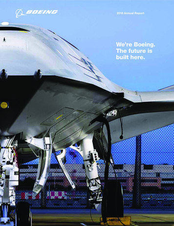
outboard actuator. Concurrent with this action, the ACE also arms the “Blocking” mode on the outboardactuator on the same surface. If a subsequent failure occurs that will cause the outboard actuator to beplaced in the ‘‘Damped” mode by its ACE, both actuators will then be in the ‘‘Damped” mode and havetheir ‘‘Blocking” modes armed. An elevator actuator in this configuration enters the ‘‘Blocking” mode,which hydraulically locks the surface in place for flutter protection.11.5.2 Mechanical ControlSpoiler panel 4 and 11 and the alternate stabilizer pitch trim system are controlled mechanically ratherthan electrically. Spoilers 4 and 11 are driven directly from control wheel deflections via a control cable.The alternate horizontal stabilizer control is accomplished by using the pitch trim levers on the flight deckaisle stand. Electrical switches actuated by the alternate trim levers allow the PFCs to determine whenalternate trim is being commanded so that appropriate commands can be given to the pitch control laws.Spoiler panels 4 and 11 are also used as speedbrakes, both in the air and on the ground. The speedbrakefunction for this spoiler pair only has two positions: stowed and fully extended. The speedbrake commandsfor spoilers 4 and 11 are electrical in nature, with an ACE giving an extend or retract command to a solenoidoperated valve in each of the actuators. Once that spoiler pair has been deployed by a speedbrake command,there is no control wheel speedbrake command mixing, as there is on all the other fly-by-wire spoiler surfaces.FIGURE 11.4Schematic representation of the Boeing 777 Primary Flight Control System hydraulic power andelectronic control functional distribution.11.6 Fault Tolerance‘‘Fault Tolerance” is a term that is used to define the ability of any system to withstand single or multiplefailures which results in either no loss of functionality or a known loss of functionality or reduced levelof redundancy while maintaining the required level of safety. It does not, however, define any particularmethod that is used for this purpose. There are two major classes of faults that any system design must 2001 by CRC Press LLC
deal with. These are A failure which results in some particular component becoming totally inoperative. An exampleof this would be a loss of power to some electronic component, such that it no longer performsits intended function. A failure which results in some particular component remaining active, but the functionality itprovides is in error. An example of this failure would be a Low Range Radio Altimeter whoseoutput is indicating the airplane is at an altitude 500 ft above the ground when the airplane isactually 200 ft above the ground.One method that is used to address the first class of faults is the use of redundant elements. For example,there are three PFCs in the 777 Primary Flight Control System, each with three identical computing ‘‘lanes”within each PFC. This results in nine identical computing channels. Any of the three PFCs themselves canfail totally due to loss of power or some other failure which affects all three computing lanes, but thePrimary Flight Control System loses no functionality. All four ACEs will continue to receive all their surfaceposition commands from the remaining PFCs. All that is affected is the level of available redundancy.Likewise, any single computing lane within a PFC can fail, and that PFC itself will continue to operatewith no loss of functionality. The only thing that is affected is the amount of redundancy of the system.The 777 is certified to be dispatched on a revenue flight, per the Minimum Equipment List (MEL), withtwo computing lanes out of the nine total (as long as they are not within the same PFC channel) for 10days and for a single day with one total PFC channel inoperative.Likewise, there is fault tolerance in the ACE architecture. The flight control functions are distributedamong the four ACEs such that a total failure of a single ACE will leave the major functionality of thesystem intact. A single actuator on several of the primary control surfaces may become inoperative dueto this failure, and a certain number of spoiler symmetrical panel pairs will be lost. However, the pilotflying the airplane will notice little or no difference in handling characteristics with this failure. A totalACE failure of this nature will have much the same impact to the Primary Flight Control System as thatof a hydraulic system failure.The second class of faults is one that results in erroneous operation of a specific component of the system.The normal design practice to account for failures of this type is to have multiple elements doing the sametask and their outputs voted or compared in some manner. This is sometimes referred to as a “voting plane.’’All critical interfaces into the 777 FBW Primary Flight Control System use multiple inputs which arecompared by a voting plane. For interfaces that are required to remain operable after a first failure, at leastthree inputs must be used. For example, there are three individual Low Range Radio Altimeter (LRRA)inputs used by the PFCs. The PFCs compare all three inputs and calculates a mid-value select on the threevalues; i.e., the middle value LRRA input is used in all calculations which require radio altitude. In thismanner, any single failure of an LRRA that results in an erroneous value will be discarded. If a subsequentfailure occurs which causes the remaining two LRRA signals to disagree by a preset amount, the PFCs willthrow out both values and take appropriate action in those functions which use these data.Additionally, a voting plane scheme is used by the PFCs on themselves. Normally, a single computinglane within a PFC channel is declared as the ‘‘master” lane, and that lane is responsible for transmittingall data onto the data busses for use by the ACEs and other airplane systems. However, all three lanesare simultaneously computing the same control laws. The outputs of all three computing lanes within asingle PFC channel are compared against each other. Any failure of a lane that will cause an erroneousoutput from that lane will cause that lane to be condemned as ‘‘failed” by the other two lanes.Likewise, the outputs from all three PFC channels themselves are compared. Each PFC looks at itsown calculated command output for any particular actuator, and compares it with the same commandthat was calculated by the other two PFC channels. Each PFC channel then does a mid-value select onthe three commands, and that value (whether it was the one calculated by itself or by one of the otherPFC channels) is then output to the ACEs for the individual actuator commands. In this manner, it isassured that each ACE receives identical commands from each of the PFC channels. 2001 by CRC Press LLC
By employing methods such as those described above, it is assured that the 777 Primary Flight ControlSystem is able to withstand single or multiple failures and be able to contain those failures in such amanner that the system remains safe and does not take inappropriate action due to those failures.11.7 System Operating ModesThe 777 FBW Primary Flight Control System has three operating modes: Normal, Secondary, and Direct.These modes are defined below:Normal—In the ‘‘Normal” mode, the PFCs supply actuator position commands to the ACEs, whichconvert them into an analog servo command. Full functionality is provided, including all enhancedperformance, envelope protection, and ride quality features.Secondary—In the ‘‘Secondary” mode, the PFCs supply actuator position commands to the ACEs,just as in the ‘‘Normal” mode. However, functionality of the system is reduced. For example, theenvelope protection functions are not active in the “Secondary” mode. The PFCs enter this modeautomatically from the ‘‘Normal” mode when there are sufficient failures in the system or interfacing systems such that the ‘‘Normal” mode is no longer supported. An example of a set of failuresthat will automatically drop the system into the ‘‘Secondary” mode is total loss of airplane air datafrom the ADIRU and SAARU. The airplane is quite capable of being flown for a long period oftime in the ‘‘Secondary” mode. It cannot, however, be dispatched in this condition.Direct—In the ‘‘Direct” mode, the ACEs do not process commands from the PFCs. Instead, each ACEdecodes pilot commands directly from the pilot controller transducers and uses them for theclosed loop servo control of the actuators. This mode will automatically be entered due to totalfailure of all three PFCs, failures internal to the ACEs, loss of the flight controls ARINC 629 databusses, or some combination of these failures. It may also be selected manually via the PFCdisconnect switch on the overhead panel in the flight deck. The airplane handling characteristicsin the “Direct” mode closely match those of the ‘‘Secondary” mode.11.8 Control Laws and System FunctionalityThe design philosophy employed in the development of the 777 Primary Flight Control System controllaws stresses aircraft operation consistent with a pilot’s past training and experience. The combinationof electronic control of the system and this philosophy provides for the feel of a conventional airplane,but with improved handling characteristics and reduced pilot workload.11.8.1 Pitch ControlPitch control is accomplished through what is known as a maneuver demand control law, which alsoreferred to as a C*U control law. C* (pronounced ‘‘C-Star”) is a term that is used to describe the blendingof the airplane pitch rate and the load factor (the amount of acceleration felt by an occupant of theairplane during a maneuver). At low airspeeds, the pitch rate is the controlling factor. That is, a specificpush or pull of the column by the pilot will result in some given pitch rate of the airplane. The harderthe pilot pushes or pulls on the column, the faster the airplane will pitch nose up or nose down. At highairspeeds, the load factor dominates. This means that, at high airspeeds, a specific push or pull of thecolumn by the pilot will result in some given load factor.The ‘‘U” term in C*U refers to the feature in the control law which will, for any change in the airspeedaway from a referenced trim speed, cause a pitch change to return to that referenced airspeed. For anincrease in airspeed, the control law will command the airplane nose up, which tends to slow the airplanedown. For a decrease in airspeed, the control law causes a corresponding speed increase by commanding 2001 by CRC Press LLC
the airplane nose down. This introduces an element of speed stability into the airplane pitch control.However, airplane configuration changes, such as a change in the trailing edge flap setting or loweringthe landing gear, will NOT result in airplane pitch changes, which would require the pilot to re-trim theairplane to the new configuration. Thus, the major advantage of this type of control law is that thenuisance-handling characteristics found in a conventional, mechanically controlled flight control systemwhich increase the pilot workload are minimized or eliminated, while the desirable characteristics aremaintained.While in flight, the pitch trim switches on the Captain’s and First Officer’s control wheels do notdirectly control the horizontal stabilizer as they normally do on conventionally controlled airplanes.When the trim switches are used in flight, the pilot is actually requesting a new referenced trim speed.The airplane will pitch nose up or nose down, using the elevator surfaces, in response to that referenceairspeed change to achieve that new airspeed. The stabilizer will automatically trim, when necessary,to offload the elevator surface and allow it to return to its neutral surface when the airplane is in atrimmed condition. When the airplane is on the ground, the pitch trim switches do trim the horizontalstabilizer directly. While the alternate trim levers (described previously) move the stabilizer directly,even in flight, the act of doing so will also change the C*U referenced trim speed such that the neteffect is the same as would have been achieved if the pitch trim switches on the control wheels hadbeen used. As on a conventional airplane, trimming is required to reduce any column forces that arebeing held by the pilot.The pitch control law incorporates several additional features. One is called landing flare compensation.This function provides handling characteristics during the flare and landing maneuvers consistent withthat of a conventional airplane, which would have otherwise been significantly altered by the C*U controllaw. The pitch control law also incorporates Stall and Overspeed Protection. These functions will notallow the referenced trim speed to be set below a predefined minimum value or above the maximumoperating speed of the airplane. They also significantly increase the column force that the pilot musthold in order to fly above or below those speeds. An additional feature incorporated into the pitch controllaw is turn compensation, which enables the pilot to maintain a constant altitude with minimal columninput during a banked turn.The unique 777 implementation of maneuver demand and speed stability in the pitch control lawsmeans that: An established flight path remains unchanged unless the pilot changes it through a control columninput, or if the airspeed changes and the speed stability function takes effect. Trimming is required only for airspeed changes and not for airplane configuration changes.11.8.2 Yaw ControlThe yaw control law contains the usual functionality employed on other Boeing jetliners, such as the yawdamper and rudder ratio changer (which compensates a rudder command as a function of airspeed).However, the 777 FBW rudder control system has no separate actuators, linkages, and wiring for thesefunctions, as have been used in previous airplane models. Rather, the command for these functions arecalculated in the PFCs and included as part of the normal rudder command to the main rudder actuators.This reduces weight, complexity, maintenance, and spares required to be stocked.The yaw control law also incorporates several addition features. The gust suppression system reducesairplane tag wag by sensing wind gusts via pressure transducers mounted on the vertical tail fin andapplying a rudder command to oppose the movement that would have otherwise been generated by thegust. Another feature is the wheel-rudder crosstie function, which reduces sideslip by using small amountsof rudder during banked turns.One important feature in the yaw control is Thrust Asymmetry Compensation, or TAC. This functionautomatically applies a rudder input for any thrust asymmetry between the two engines which exceed 2001 by CRC Press LLC
approximately 10% of the rated thrust. This is intended to cancel the yawing moment associated withan engine failure. TAC operates at all airspeeds above 80 kn even on the ground during the take-off roll.It will not operate when the engine thrust reversers are deployed.11.8.3 Roll ControlThe roll control law utilized by t
11.4.3 ARINC 629 Data Bus The ACEs and PFCs communicate with each other, as well as with all other systems on the airplane, via triplex, bi-directional ARINC 629 Flight Controls data busses, referred to as L, C, and R. The connection from these electronic units to each of the data busses is via a stub cable and an ARINC 629 coupler. Each