Transcription
VialsamplersAgilent InfinityLab LC SeriesUser ManualAgilent InfinityLab LC Series Vialsamplers User Manual
NoticesDocument InformationWarrantyDocument No: SD-29000242 Rev. EPart No: G7129-90010 Rev. EEDITION 04/2020The material contained in this documentis provided “as is,” and is subject to beingchanged, without notice, in future editions. Further, to the maximum extentpermitted by applicable law, Agilent disclaims all warranties, either express orimplied, with regard to this manual andany information contained herein, including but not limited to the implied warranties of merchantability and fitness for aparticular purpose. Agilent shall not be liable for errors or for incidental or consequential damages in connection with thefurnishing, use, or performance of thisdocument or of any information contained herein. Should Agilent and the userhave a separate written agreement withwarranty terms covering the material inthis document that conflict with theseterms, the warranty terms in the separateagreement shall control.Copyright Agilent Technologies, Inc. 2015-2020No part of this manual may be reproduced in any form or by any means(including electronic storage and retrievalor translation into a foreign language)without prior agreement and written consent from Agilent Technologies, Inc. asgoverned by United States and international copyright laws.Agilent TechnologiesHewlett-Packard-Strasse 876337 WaldbronnTechnology LicensesThe hardware and/or software describedin this document are furnished under alicense and may be used or copied only inaccordance with the terms of suchlicense.Safety NoticesC AU T I O NA CAUTION notice denotes ahazard. It calls attention to anoperating procedure, practice, orthe like that, if not correctly performed or adhered to, could resultin damage to the product or lossof important data. Do not proceedbeyond a CAUTION notice untilthe indicated conditions are fullyunderstood and met.WAR N IN GA WARNING notice denotes ahazard. It calls attention to anoperating procedure, practice, orthe like that, if not correctly performed or adhered to, couldresult in personal injury or death.Do not proceed beyond a WARNING notice until the indicatedconditions are fully understoodand met.Restricted Rights LegendU.S. Government Restricted Rights. Software and technical data rights granted tothe federal government include onlythose rights customarily provided to enduser customers. Agilent provides thiscustomary commercial license in Software and technical data pursuant to FAR12.211 (Technical Data) and 12.212(Computer Software) and, for the Department of Defense, DFARS 252.227-7015(Technical Data - Commercial Items) andDFARS 227.7202-3 (Rights in Commercial Computer Software or ComputerSoftware Documentation).Agilent InfinityLab LC Series Vialsamplers User Manual
In This Book:This manual covers the following modules:1 Agilent 1260 Infinity II Vialsampler (G7129A) Agilent 1290 Infinity II Vialsampler (G7129B) Agilent 1260 Infinity II Vialsampler (G7129C)IntroductionThis chapter gives an introduction to the module and instrument overview.2Site Requirements and SpecificationsThis chapter provides information on environmental requirements, physical andperformance specifications.3Using the ModuleThis chapter provides information on how to use the module.4Preparing the ModuleThis chapter explains the operational parameters of the module.5Optimizing PerformanceThis chapter provides information on how to optimize the module.6Troubleshooting and DiagnosticsThis chapter gives an overview of the maintenance, troubleshooting, anddiagnostic features available for the Agilent InfinityLab Series Vialsampler.7Error InformationThis chapter describes the meaning of error messages, and provides informationon probable causes and suggested actions how to recover from error conditions.Agilent InfinityLab LC Series Vialsamplers User Manual3
8MaintenanceThis chapter describes the maintenance of the module.9Parts and Materials for MaintenanceThis chapter provides information on parts for maintenance.10Identifying CablesThis chapter provides information on cables used with the Agilent 1200 InfinitySeries modules.11Hardware InformationThis chapter describes the detector in more detail on hardware and electronics.12LAN ConfigurationThis chapter provides information on connecting the module to the AgilentChemStation PC.13AppendixThis chapter provides additional information on safety, legal and web.Agilent InfinityLab LC Series Vialsamplers User Manual4
Contents1Introduction9Product Description (G7129A) 10Features (G7129A) 11Product Description (G7129B) 12Features (G7129B) 13Product Description (G7129C) 14Features (G7129C) 15Overview of the Module 16Operating Principle 18Leak and Waste Handling 272Site Requirements and Specifications33Site Requirements 34Physical Specifications 38Performance Specifications 39Specifications of the Sample Cooler 47Specifications of the Sample Thermostat 49Specifications of the Integrated Column Compartment3Using the Module5153Magnets 55Turn on/off 56Status Indicators 58Vial Drawers and Trays 59Choice of Vials and Caps 70Install the Optional Integrated Column Compartment 74Using the Optional Integrated Column Compartment 96Install the Optional Sample Cooler/Sample Thermostat 116Using the Optional Sample Cooler/Sample Thermostat 123Transporting the Sampler 132Agilent Local Control Modules 137Agilent InfinityLab LC Series Vialsamplers User Manual5
4Preparing the Module139Leak and Waste Handling 140Preparing the Module 141Solvent Information 142Capillary Color Coding Guide 149Installing Capillaries 150Flow Connections to the VialsamplerSetting up the Vialsampler 1545Optimizing Performance152166Optimization for Lowest Carryover 167Fast Injection Cycle and Low Delay VolumePrecise Injection Volume 173Choice of Rotor Seal 1756Troubleshooting and Diagnostics176Status Indicators 177Overview of Tests and Tools 178Maintenance and Troubleshooting ToolsDiagnostic Tests 187Agilent Lab Advisor Software 1897Error Information171179190What are Error Messages 192General Error Messages 193Vialsampler Error Messages 201Sample Cooler/Sample Thermostat Error Messages 213Integrated Column Compartment (ICC) Heater Error MessagesAgilent InfinityLab LC Series Vialsamplers User Manual2196
8Maintenance222Introduction to Maintenance 223Warnings and Cautions 224Overview of Maintenance 226Cleaning the Module 227Remove and Install Doors 228Exchange the Needle Assembly 229Exchange the Needle Seat Assembly 235Exchange the Sample Loop Assembly 241Exchange the Rotor Seal 245Exchange the Metering Seal and Piston 250Replace the Analytical Heads 255Exchange the Gripper Arm 258Replace the Peristaltic Pump Cartridge 261Exchange the Wash Port Assembly 263Replace the Module Firmware 269Replace the Sample Cooler/Sample Thermostat9Parts and Materials for Maintenance270275Standard Parts For Maintenance 276Accessory Kits 279Vial Drawers and Trays 283Multidraw Kits 286Sample Thermostat Upgrade 287Integrated Column Compartment 288Column ID Upgrade Kit 289Parts for 900 µL Injection Upgrade 290Cabinet and Door Kits 291Analytical Head Assembly (100 µL) 295Analytical-Head Assembly (900 µL) 296Analytical Head Assembly (40 μL) 2972 Position/6 Port Injection Valve, 600 bar 2982 Position/6 Port Injection Valve, 800 bar 2992 Position/6 Port Injection Valve, 1300 bar 300Agilent InfinityLab LC Series Vialsamplers User Manual7
10Identifying Cables301Cable Overview 302Analog Cables 304Remote Cables 306CAN/LAN Cables 310RS-232 Cables 311USB 31211Hardware Information313Firmware Description 314Electrical Connections 317Interfaces 319Setting the 6-bit Configuration Switch 326Instrument Layout 330Early Maintenance Feedback (EMF) 33112LAN Configuration332What You Have to Do First 333TCP/IP parameter configuration 334Configuration Switches 335Initialization Mode Selection 336Dynamic Host Configuration Protocol (DHCP)Manual Configuration 341PC and Agilent ChemStation Setup 34513Appendix338354General Safety Information 355Waste Electrical and Electronic Equipment (WEEE) DirectiveRefrigerant 362Radio Interference 365Sound Emission 366Solvent Information 367Agilent Technologies on Internet 368Agilent InfinityLab LC Series Vialsamplers User Manual3618
1IntroductionProduct Description (G7129A)Features (G7129A)11Product Description (G7129B)Features (G7129B)1415Overview of the ModuleOperating Principle1213Product Description (G7129C)Features (G7129C)101618Sampling Sequence 18Needle Parkstation 23Hydraulic Box 24Transport Assembly 26Leak and Waste Handling27Leak Sensor 31Waste Guidance 31Waste Concept 32This chapter gives an introduction to the module and instrument overview.Agilent InfinityLab LC Series Vialsamplers User Manual9
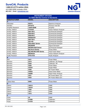
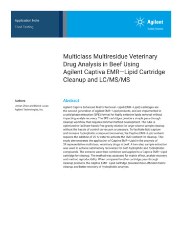
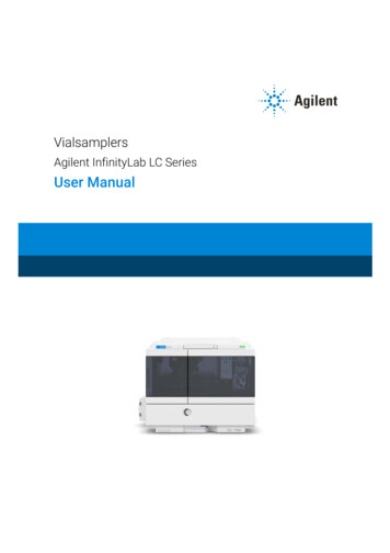
1IntroductionProduct Description (G7129A)Product Description (G7129A)The Agilent 1260 Infinity II Vialsampler is an autosampler designed for thereliability and ease-of-use needed for routine pharmaceutical tasks and qualitycontrol, as well as for environmental and food analyses. It can house optionallythe integrated column compartment for two LC columns with temperaturecontrol up to 80 C as well as a sample thermostat for stable temperatures from4 C to 40 C, all within one module.Status indicatorNeedle assemblyDrawerColumn shelfLeak drainPower switchFigure 1Overview of the VialsamplerAgilent InfinityLab LC Series Vialsamplers User Manual10
1IntroductionFeatures (G7129A)Features (G7129A) High capacity – up to 132 vials (2 mL) or up to 36 vials (6 mL). Reliable injections – 0.1 to 100 µL injections for up to 600 bar (G7129A) andup to 800 bar (G7129C). Easy volume extensions – for injection volumes up to 1800 µL for applicationsranging from microbore to semipreparative chromatography. Lowest carryover – with an in needle flush port included, for rinsing the outsideof the needle. Efficient temperature control – with an integrated column compartment asoption or upgrade available. Which holds two columns up to 30 cm length,and provides heating capacity from 5 C above ambient up to 80 C forreproducible chromatography data at optimized resolution. Integrated sample thermostat – available as option or upgrade, providingcooling and heating in the range from 4 C - 40 C. Low internal volume – for minimum contribution to a system's total internalvolume, which can be even further reduced using "bypass" mode. Increased productivity – with overlapped injections. Customizable injection program – available for customizing advancedinjections as well as for sample preparation steps upfront injection.Agilent InfinityLab LC Series Vialsamplers User Manual11
1IntroductionProduct Description (G7129B)Product Description (G7129B)The Agilent 1290 Infinity II Vialsampler (G7129B) is an autosampler designed forUHPLC applications up to 1300 bar. It provides the reliability, safety, andease-of-use needed for routine pharmaceutical tasks and quality control, as wellas for environmental and food analyses. It can house optionally the integratedcolumn compartment for two LC columns with temperature control up to 80 Cas well as a sample thermostat for stable temperatures from 4 C to 40 C, allwithin one module.Status indicatorNeedle assemblyDrawerColumn shelfLeak drainPower switchFigure 2Overview of the VialsamplerAgilent InfinityLab LC Series Vialsamplers User Manual12
1IntroductionFeatures (G7129B)Features (G7129B) Accurate and precise injections - within a wide and flexible range of volumes High capacity - up to 132 vials (2 mL) or up to 36 vials (6 mL). Easy volume extensions - for injection volumes up to 1500 µL for applicationsranging from microbore to semipreparative chromatography. Lowest carryover - with an in needle flush port included, for rinsing the outsideof the needle. Efficient temperature control - with an integrated column compartment asoption or upgrade available. Which holds two columns up to 30 cm length,and provides heating capacity from 5 C above ambient up to 80 C forreproducible chromatography data at optimized resolution. Integrated sample thermostat - available as option or upgrade, providingcooling and heating in the range from 4 – 40 C. Low internal volume - for minimum contribution to a system's total internalvolume, which can be even further reduced using bypass mode. Increased productivity - with overlapped injections. Customizable Injection program - available for customizing advancedinjections as well as for sample preparation steps upfront injection.Agilent InfinityLab LC Series Vialsamplers User Manual13
1IntroductionProduct Description (G7129C)Product Description (G7129C)The Agilent 1260 Infinity II Vialsampler is an autosampler designed for thereliability and ease-of-use needed for routine pharmaceutical tasks and qualitycontrol, as well as for environmental and food analyses. It can house optionallythe integrated column compartment for two LC columns with temperaturecontrol up to 80 C as well as a sample thermostat for stable temperatures from4 C to 40 C, all within one module.Status indicatorNeedle assemblyDrawerColumn shelfLeak drainPower switchFigure 3Overview of the VialsamplerAgilent InfinityLab LC Series Vialsamplers User Manual14
1IntroductionFeatures (G7129C)Features (G7129C) High capacity – up to 132 vials (2 mL) or up to 36 vials (6 mL). Reliable injections – 0.1 to 100 µL injections for up to 600 bar (G7129A) andup to 800 bar (G7129C). Easy volume extensions – for injection volumes up to 1800 µL for applicationsranging from microbore to semipreparative chromatography. Lowest carryover – with an in needle flush port included, for rinsing the outsideof the needle. Efficient temperature control – with an integrated column compartment asoption or upgrade available. Which holds two columns up to 30 cm length,and provides heating capacity from 5 C above ambient up to 80 C forreproducible chromatography data at optimized resolution. Integrated sample thermostat – available as option or upgrade, providingcooling and heating in the range from 4 C - 40 C. Low internal volume – for minimum contribution to a system's total internalvolume, which can be even further reduced using "bypass" mode. Increased productivity – with overlapped injections. Customizable injection program – available for customizing advancedinjections as well as for sample preparation steps upfront injection.Agilent InfinityLab LC Series Vialsamplers User Manual15
1IntroductionOverview of the ModuleOverview of the ModuleThe Agilent InfinityLab LC Series Vialsampler is designed for use with othermodules of the Agilent InfinityLab LC Series, 1200 Series, and 1100 Series LC, aswell as with other LC systems with adequate remote-control capabilities. TheVialsampler can be controlled from any computer with a suitablechromatography data system (for example, Agilent OpenLab CDS, MassHunter,etc.) or via an Agilent local control module (InfinityLab Companion or 1200Infinity Series Instant Pilot).The 1290 Infinity II Vialsampler (G7129B) can be operated at up to 1300 bar. Thetwo 1260 Infinity II Vialsampler variants (G7129A and G7129C) are limited to amaximum system pressure of 600 and 800 bar, respectively.The Vialsampler can accommodate two vial drawers, providing space for up to132 samples. The two cartesian vial drawers allow for the use of either 66 2 mLor 18 6 mL vials. A pair of classic vial drawers with a numerical vial assignmentsystem is also available, each capable of hosting 50 2 mL vials. The classic vialdrawers are designed to ease method transfer from older Agilent samplers. TheVialsampler can also be equipped with an external tray, which can be beneficialfor automation. The Agilent WalkUp solution fully supports the external tray.The Vialsampler features a robotic gripper arm for the transport of vials, driven byfour stepper motors to ensure the highest precision and flexibility for thetransport movement.The default configuration of the analytical head and sample loop allows aninjection range from 0.1 – 20 μL for the 1290 Infinity II Vialsampler and0.1 – 100 μL for the 1260 Infinity II Vialsamplers. An analytical head withextended volume is also available for injection volumes from 0.1 – 900 μL, andcan be operated at up to 400 bar. With the Multidraw Kit, the maximum injectionvolume can even reach 1800 μL.The 2-position/6-port injection valve is driven by a high-speed, hybrid steppermotor, ensuring smooth switching between the mainpass and bypass positions.Thanks to the flow-through design of the Vialsampler, the eluent continuouslyrinses the component parts of the sample introduction system. This, togetherwith the automated needle wash function for rinsing the outer surface of theneedle, ensures the lowest level of carryover for each analysis. For advanceddelay volume reduction, the injection valve can be programmed to automaticallyswitch back to the bypass position when the injection is completed.Agilent InfinityLab LC Series Vialsamplers User Manual16
1IntroductionOverview of the ModuleThe Agilent InfinityLab Integrated Column Compartment, an optional upgrade forthe Vialsampler, eliminates the need for having a standalone column thermostatin the LC stack. It has the heating capability of reaching temperatures up to 80 Cand can hold a total of two columns with maximum lengths of 30 cm.For applications requiring control over the vial temperature, the Vialsampler canbe equipped with the Agilent InfinityLab Sample Thermostat (G7167-60101). Itfeatures a vapor-compression refrigeration system and an electric heater,allowing the Vialsampler to reach vial temperatures down to 4 C and up to 40 C.Agilent InfinityLab LC Series Vialsamplers User Manual17
1IntroductionOperating PrincipleOperating PrincipleSampling SequenceThe Vialsampler processor continuously monitors the movements of thevialsampler components during the sampling sequence. The processor definesspecific time windows and mechanical ranges for each movement. If a specificstep of the sampling sequence can’t be completed successfully, an errormessage is generated.During the sampling sequence, the solvent bypasses the vialsampler via theinjection valve. The gripper arm selects the sample vial, either from a staticsample rack, or from external vial positions. The gripper arm places the samplevial below the injection needle. The required volume of sample is drawn into thesample loop by the metering device. Sample is applied to the column when theinjection valve returns to the mainpass (main path) position at the end of thesampling sequence.The sampling sequence occurs in the following order:1 The injection valve switches to the bypass position.2 The piston of the metering device moves to the initialization position.3 The gripper arm moves from the home position, and selects the vial. At thesame time, the needle lifts out of the seat.4 The gripper moves into the needle station and stops in the draw position.15 The needle lowers into the vial.6 The metering device draws the defined sample volume.7 The needle lifts out of the vial.8 The gripper arm moves out slightly and stops in the wash position1.9 The needle moves downwards and dips into the wash well of the wash port.Simultaneously the peristaltic pump delivers the flush solvent.110 The needle moves back.111 The gripper arm moves out of the needle station and the wash port snapsback in position.1only if automated needle wash is selected. If this feature is disabled, the gripper armpositions the sample vial directly below the needle (Step 4) and lowers the needle intothe vial.Agilent InfinityLab LC Series Vialsamplers User Manual18
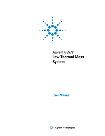
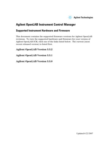
1IntroductionOperating Principle12 The gripper arm replaces the vial, and returns to the home position.Simultaneously, the needle lowers into the seat.13 The injection valve switches to the mainpass (main path) position.Injection SequenceBefore the start of the injection sequence, and during an analysis, the injectionvalve is in the mainpass (main path) position (see Figure 4 on page 19). In thisposition, the mobile phase flows through the autosamplers metering device,sample loop, and needle. This ensures that all parts in contact with sample areflushed during the run, thus minimizing carryover.SolventSampling gure 4Mainpass (main path) Position - standard position during runs and when the sampleris idleAgilent InfinityLab LC Series Vialsamplers User Manual19
1IntroductionOperating PrincipleWhen the sample sequence begins, the valve unit switches to the bypassposition (see Figure 5 on page 20). Solvent from the pump enters the valve unit atport 1, and flows directly to the column through port 6.SolventSampling gure 5Valve in bypass - needle in vial, metering device aspirates sample volumeAgilent InfinityLab LC Series Vialsamplers User Manual20
1IntroductionOperating PrincipleThen the vial is positioned below the needle. The needle moves down into thevial, the metering unit draws the required sample volume into the loop, and theneedle is raised. In the next step, the needle is washed (see Figure 6 on page 21).SolventSampling gure 6Outer face of needle getting washed in wash portAgilent InfinityLab LC Series Vialsamplers User Manual21
1IntroductionOperating PrincipleWhen the metering unit has drawn the required volume of sample into thesample loop, the vial is replaced in the sample tray. The wash port flips into theorigin position, the needle is lowered into the needle seat, and the injection valveswitches back to mainpass (main path) position, flushing the sample onto thecolumn (see Figure 7 on page 22).SolventSampling gure 7Valve switches to mainpass (main path) - sample is transferred towards the LC columnAgilent InfinityLab LC Series Vialsamplers User Manual22
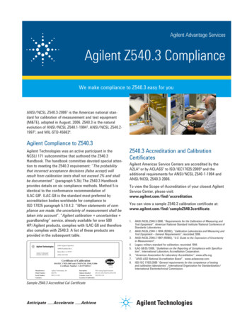
1IntroductionOperating PrincipleNeedle ParkstationThe needle parkstation comprises two main assemblies: needle drive and washport.Figure 8Needle StationNeedle-DriveThe needle movement is driven by a stepper motor connected to the spindleassembly by a toothed belt. The circular motion of the motor is converted tolinear motion by the drive nut on the spindle assembly. The upper and lowerneedle positions are detected by reflection sensors on the needle station board,while the needle-in-vial position is determined by counting the motor steps fromthe upper needle-sensor position.Agilent InfinityLab LC Series Vialsamplers User Manual23
1IntroductionOperating PrincipleHydraulic BoxThe hydraulic box comprises two main assemblies: metering device, andinjection valve.Figure 9NOTEHydraulic UnitThe replacement hydraulic box excludes the injection valve and metering headassemblies.Agilent InfinityLab LC Series Vialsamplers User Manual24
1IntroductionOperating PrincipleAnalytical HeadThe analytical head is driven by the stepper motor that is connected to the driveshaft by a toothed belt. The drive nut on the spindle converts the circularmovement of the spindle to linear motion. The drive nut pushes the sapphirepiston against the tension of the spring into the analytical head. The base of thepiston sits on the large bearing of the drive nut, which ensures the piston isalways centered. A ceramic ring guides the movement of the piston in theanalytical head. The home position of the piston is sensed by an optical sensoron the hydraulic unit board while the sample volume is determined by countingthe number of steps from the home position. The backward movement of thepiston (driven by the spring) draws sample from the vial.Injection ValveThe two-position 6-port injection valve is driven by a stepper motor. Only five ofthe six ports are used (port 3 is not used). A lever/slider mechanism transfers themovement of the stepper motor to the injection valve. Two microswitchesmonitor switching of the valve (bypass and mainpass (main path) end positions).No valve adjustments are required after replacing internal components.Agilent InfinityLab LC Series Vialsamplers User Manual25
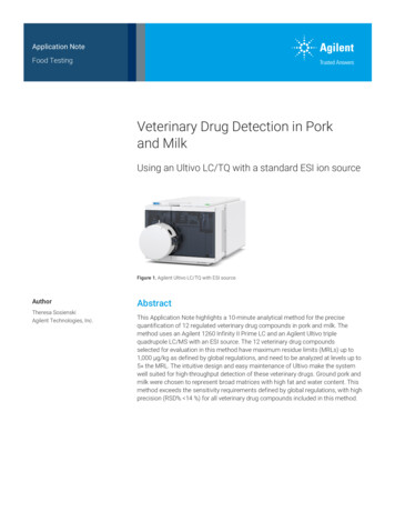
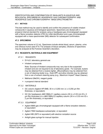
1IntroductionOperating PrincipleTransport AssemblyThe transport unit comprises an X-axis slide (left-right motion), a Z-axis arm(up-down motion), and a gripper assembly (rotation and vial-gripping).X motorTheta motorGripper motorZ axisX axisGripper armTheta axisZ motorFlex boardFigure 10Transport AssemblyThe transport assembly uses four stepper motors driven in closed-loop mode foraccurate positioning of the gripper assembly. The rotational movement of themotors is converted to linear motion (X- and Z-axes) by toothed belts connectedto the drive spindles. The rotation (theta axes) of the gripper assembly istransferred from the motor by a toothed belt and series of gears. The openingand closing of the gripper fingers are driven by a stepper motor linked by atoothed belt to the planetary gearing inside the gripper assembly.The stepper motor positions are determined by the optical encoders mountedonto the stepper-motor housing. The encoders monitor the position of themotors continually, and correct for position errors automatically (e.g. if thegripper is accidentally moved out of position when loading vials into the vial tray).The initialization positions of the moving components are sensed by reflectionsensors mounted on the flex board. These positions are used by the processor tocalculate the actual motor position. An additional six reflection sensors for trayrecognition are mounted on the flex board at the front of the assembly.Agilent InfinityLab LC Series Vialsamplers User Manual26
1IntroductionLeak and Waste HandlingLeak and Waste HandlingThe Agilent InfinityLab LC Series has been designed for safe leak and wastehandling. It is important that all security concepts are understood andinstructions are carefully followed.The solvent cabinet is designed to store a maximum volume of 8 L solvent. Themaximum volume for an individual bottle stored in the solvent cabinet should notexceed 2 L. For details, see the usage guideline for the Agilent Infinity II SolventCabinets (a printed copy of the guideline has been shipped with the solventcabinet, electronic copies are available on the Internet).All leak plane outlets are situated in a consistent position so that all Infinity andInfinity II modules can be stacked on top of each other. Waste tubes are guidedthrough a channel on the right hand side of the instrument, keeping the frontaccess clear from tubes.The leak plane provides leak management by catching all internal liquid leaks,guiding them to the leak sensor for leak detection, and passing them on to thenext module below, if the leak sensor fails. The leak sensor in the leak planestops the running system as soon as the leak detection level is reached.Solvent and condensate is guided through the waste channel into the wastecontainer: from the detector's flow cell outlet from the Multisampler needle wash port from the Sample Cooler or Sample Thermostat (condensate) from the pump's Seal Wash Sensor (if applicable) from the pump's Purge Valve or Multipurpose ValveAgilent InfinityLab LC Series Vialsamplers User Manual27
1IntroductionLeak and Waste HandlingFigure 11Infinity II Leak Waste Concept (Flex Bench installation)Agilent InfinityLab LC Series Vialsamplers User Manual28
1IntroductionLeak and Waste HandlingFigure 12Infinity II Single Stack Leak Waste Concept (bench installation)Agilent InfinityLab LC Series Vialsamplers User Manual29
1IntroductionLeak and Waste HandlingFigure 13Infinity II Two Stack Leak Waste Concept (bench installation)The waste tube connected to the leak plane outlet on each of the bottominstruments guides the solvent to a suitable waste container.Agilent InfinityLab LC Series Vialsamplers User Manual30
1IntroductionLeak and Waste HandlingLeak SensorC AU T I O NSolvent incompatibilityThe solvent DMF (dimethyl formamide) leads to corrosion of the leak sensor.The material of the leak sensor, PVDF (polyvinylidene fluoride), is incompatiblewith DMF. Do not use DMF as mobile phase. Check the leak sensor regularly for corrosion.NOTEThe leak sensor in the sampler is hidden under the ICC Column Heater or ColumnShelf respectively.Waste GuidanceNOTEThe waste drainage must go straight into the waste containers. The waste flowmust not be restricted at bends or joints.Agilent InfinityLab LC Series Vialsamplers User Manual31
1IntroductionLeak and Waste HandlingWaste Concept1 Agilent recommends using the 6 L waste can with 1 Stay Safe cap GL45 with4 ports (5043-1221) for optimal and safe waste disposal. If you decide to useyour own waste solution, make sure that the tubes don't immerse in the liquid.Agilent InfinityLab LC Series Vialsamplers User Manual32
2Site Requirements and SpecificationsSite Requirements34Physical Specifications38Performance SpecificationsPerformance Specifications (G7129A)Performance Specifications (G7129B)Performance Specifications (G7129C)39394245Specifications of the Sample Cooler47Specifications of the Sample Thermostat49Specifications of the Integrated Column Compartment51This chapter provides information on environmental requirements, physical andperformance specifications.Agilent InfinityLab LC Series Vialsamplers User Manual33
2Site Requirements and SpecificationsSite RequirementsSite RequirementsSite RequirementsA suitable environment is important to ensure optimum performance of theinstrument.Power ConsiderationsThe module power supply has wide ranging capability. It accepts any line voltagein the range described in Table 1 on page 38. Consequently there is no voltageselector in the rear of the module. There are also no externally accessible fuses,because automatic electronic fuses are implemented in the power supply.WAR N IN GHazard of electrical shock or damage of your instrumentationcan result, if the devices are connected to a line
Agilent InfinityLab LC Series Vialsamplers User Manual Notices Document Information Document No: SD-29000242 Rev. E Part No: G7129-90010 Rev. E EDITION 04/2020