Transcription
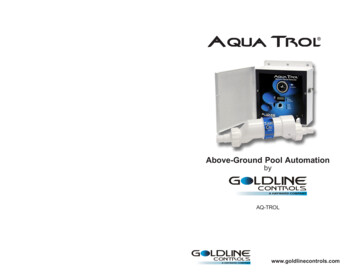
MonthlyWeeklyTESTFree Chlorine1.0 - 3.0 ppmpH7.2 - 7.8Alkalinity80 - 120 ppmSaltQuarterlyIDEAL RANGEADJUSTMENT REQUIREDAutomation and ChlorinationRaise desired output % toincrease, lower desired output %to decrease -OR- increase ordecrease pump filtration time.Too high - add muriatic acidToo low - add soda ash.Add baking soda to increase.Add acid as required to decrease.2700 - 3400 ppm Add salt as required to increase.Stabilizer60 - 80 ppmAdd cyanuric acid to increase.Calcium200 - 400 ppmAdd calcium to increase.Drain and add water to decrease.Electrolytic Cell inspect & cleanRefer to section in manual.Operation Manualfor modelsPL-PLUSPL-PLUS-20GLDLINEGC ON TROLSNorth Kingstown, RI 02852 USA092360DCopyright 2009 Goldline ControlsLDLINEC ON TROLSwww.goldlinecontrols.com888-921-7665
LIMITED WARRANTY (effective 04/01/09) Hayward/Goldline warrants its Pro Logic and E-Commandpool automation products as well as its Aqua Rite, Aqua Rite Pro, Aqua Plus and SwimPure chlorinationproducts to be free of defects in materials and workmanship, under normal use and service, for a period of three(3) years. Hayward/Goldline also warrants its Aqua Trol chlorination products to be free of defects in materialsand workmanship, under normal use and service for a period of one (1) year. These warranties are applicablefrom the initial date of installation on private residential swimming pools in the US and Canada.IMPORTANT SAFETY INSTRUCTIONSWhen using this electrical equipment, basic safety precautions should alwaysbe followed, including the following: READ AND FOLLOW ALL INSTRUCTIONS!WARNING: Disconnect all AC power during installation. !WARNING: Water in excess of 100 degrees Fahrenheit may behazardous to your health. !WARNING: To reduce the risk of injury, do not permit children touse this product unless they are closely supervised at all times. A green colored terminal marked “Grounding” is located inside the wiringcompartment. To reduce the risk of electric shock, this terminal must beconnected to the grounding means provided in the electric supply servicepanel with a continuous copper wire equivalent in size to the circuitconductors supplying the equipment.One bonding lug for US models (two for Canadian models) is provided on theexternal surface. To reduce the risk of electric shock, connect the localcommon bonding grid in the area of the swimming pool, spa, or hot tub tothese terminals with an insulated or bare copper conductor not smaller than 8AWG US / 6 AWG Canada.All field installed metal components such as rails, ladders, drains, or othersimilar hardware within 3 meters of the pool, spa or hot tub shall be bondedto the equipment grounding bus with copper conductors not smaller than8 AWG US / 6 AWG Canada.SAVE THESE INSTRUCTIONSHayward/Goldline warrants all the above-identified pool automation and chlorination products installed oncommercial swimming pools and on swimming pools outside of the US and Canada for a period of one (1) year.Likewise, Hayward/Goldline warrants all accessories and replacement parts for the above-identified poolautomation and chlorination products for a period of one (1) year. Each of these warranties is not transferableand applies only to the original owner.Proof of purchase is required for warranty service. If written proof of purchase is not provided, the manufacturing date code will be the sole determinant of the date of installation of the product. To obtain warranty serviceor repair, please contact the place of purchase or the nearest Hayward/Goldline authorized warranty servicecenter. For more information on authorized service centers please contact the Hayward/Goldline TechnicalService Support Center (61 Whitecap Road, North Kingstown RI, 02852) or visit the Goldline web site atwww.goldlinecontrols.com or the Hayward website at www.haywardnet.com.WARRANTY EXCLUSIONS:1. Material supplied or workmanship performed by others in process of installation.2. Damage resulting from improper installation including installation on pools larger than the product rating.3. Problems resulting from failure to install, operate or maintain the product(s) in accordance with the recommendations contained in the owners manual(s).4. Problems resulting from failure to maintain pool water chemistry in accordance with the recommendations inthe owners manual(s).5. Problems resulting from tampering, accident, abuse, negligence, unauthorized repairs or alternations, fire,flood, lightning, freezing, external water, degradation of natural stone used in or immediately adjacent to a poolor spa, war or acts of God.DISCLAIMER. THE EXPRESS LIMITED WARRANTIES ABOVE CONSTITUTE THE ENTIREWARRANTIES WITH RESPECT TO THE ABOVE-IDENTIFIED HAYWARD/GOLDLINE POOLAUTOMATION AND CHLORINATION PRODUCTS AND IS IN LIEU OF ALL OTHER WARRANTIES, EXPRESS OR IMPLIED, INCLUDING WARRANTIES OF MERCHANTABILITYOR FITNESS FOR A PARTICULAR PURPOSE. THESE WARRANTIES GIVE YOU SPECIFICLEGAL RIGHTS, AND YOU MAY ALSO HAVE OTHER RIGHTS OF EQUIPMENT, LOST PROFITS OR REVENUE, COSTS OF RENTING REPLACEMENTS, AND OTHER ADDITIONALEXPENSES, EVEN IF THE SELLER HAD BEEN ADVISED OF THE POSSIBILITY OF SUCHDAMAGES. SOME STATES DO NOT ALLOW THE EXCLUSION OF LIMITATION OF INCIDENTAL OR CONSEQUENTIAL DAMAGES, SO THE ABOVE LIMITATION OR EXCLUSIONMAY NOT APPLY TO YOU.NO WHOLESALER, AGENT, DEALER, CONTRACTOR OR OTHER PERSON IS AUTHORIZEDTO PROVIDE, SUPPLEMENT OR MODIFY ANY WARRANTY ON BEHALF OF HAYWARD/GOLDLINE.THESE WARRANTIES ARE VOID IF THE PRODUCT HAS BEEN ALTERED IN ANY WAY AFTER LEAVING THE FACTORY. FOR THE ABOVE-IDENTIFIED CHLORINATION PRODUCTS,THESE WARRANTIES ALSO ARE VOID IF, DURING THE WARRANTY PERIOD, YOU USE AREPLACEMENT CHLORINATOR CELL OTHER THAN AN UNMODIFIED, NEW HAYWARD/GOLDLINE CHLORINATOR CELL PURCHASED FROM HAYWARD/GOLDLINE. IF A WARRANTY BECOMES VOID, YOU STILL MAY PURCHASE SERVICE AND/OR TELEPHONETECHNICAL SUPPORT AT THE THEN CURRENT TIME AND MATERIAL RATES.36
Table of Contents35System OverviewBlock Diagram.Automation.Chlorination.Default Display.1112Manual SystemOperationFilter Pump.Lights and Aux Outputs.Pool/Spa Valves.Service.3444Automatic SystemOperation(Programming)Using the Programming Buttons.Programming Menu Flow Chart.Settings Menu.Timers Menu.Configuration Menu.Maintenance Menu.567101321Quick “How To”GuideOperate the Spa - Manually.Operate the Spa - Automatically.Set the Heater Temperature.Set the Chlorinator Output .Start/Stop Superchlorination.Program a Timeclock.Program a Countdown Timer.Enter/Exit Service Mode.2323232324242424Chlorinator Operation/Water ChemistrySaturation Index.Salt Level.Type of Salt.How to Add or Remove Salt.25262626System MaintenanceServicing and Cleaning the Turbo Cell. 29Winterizing. 29Spring Startup. 29Troubleshooting &Diagnostic InformationService Mode . 30Check System Indicator. 30Diagnostic Menu. 32WarrantyAqua Plus Warranty. 37
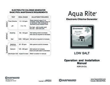
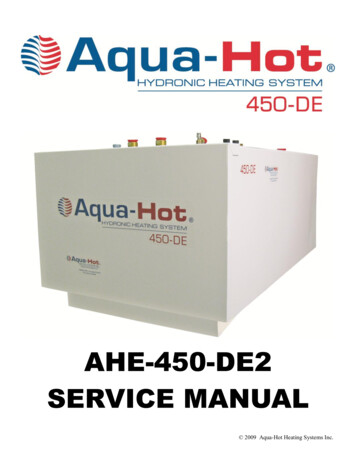
System OverviewThe Aqua Plus is a multifunction pool controller used to fully manage your pool/spa system. The Aqua Plus cancontrol pumps, valves, lighting, heaters, and chlorination. Although the Aqua Plus is easy to use, it is important tocompletely read through this operating manual before attempting to operate the control.GOptional WirelessSpaside RemotePOOLLD LIN EC ON T RO LS INC .VALVESSPAONFILTE ROFFONHEAT EROFFONLIG H TSOFFONA UX1OFFONA UX2OFFOptionalWireless BaseReceiverOptional WirelessRemote DisplayKeypadMain DisplayKeypadFilter PumpOptionalRemote DisplayKeypadLights(maximum of three)Aux 1WaterTemperatureSensors120/240VRelaysAux 2Pool/Spa Suction &Return ValvesAirSolar24V ValveActuatorsValve 3External InputHeaterFlow SwitchChlorinator Cell240 VACPowerCircuit BreakerSubpanelNOTE: This manual assumes that the Aqua Plus has been wired and configured according to the InstallationManual. Aspects of the Aqua Plus that pertain to system setup are not covered in this manual.AutomationThe Aqua Plus can control up to 4 high voltage (120/240V) pieces of equipment, up to 3 automatic valve actuators, and a conventional and solar heater. Both manual and automatic (programmed) operation are available. Allof the control functions can be programmed at a display/keypad which is part of the main unit (typically locatednear the pool equipment) or at one or more remote display/keypads.ChlorinationWith the use of the included Turbo Cell and flow switch, the Aqua Plus is also an automatic chlorine generationsystem for pool and/or spa sanitization. When enabled (see Configuration Menu), this operation requires a lowconcentration of salt (sodium chloride) in the pool/spa water. The Aqua Plus automatically converts the salt intofree chlorine which kills bacteria and algae in the pool/spa. Chlorine will revert back to sodium chloride after killingbacteria. These reactions will continuously recycle, virtually eliminating the need to add sanitizing chemicals to yourpool/spa. The only time you may need to add more salt to the pool/spa is when water is replenished due tobackwashing, draining, or splashing (not evaporation).134
Cell Temp Sensor77ºFNo functionMove to previous/next menu itemWater SensorOpen circuitNo functionMove to previous/next menu itemAir Sensor94ºFNo functionMove to previous/next menu itemSolar SensorShort circuitNo functionMove to previous/next menu itemIf the sensor appears to operating properly, then the temperature will be displayed. If this temperatureis not correct then check the placement of the sensor. If the problem is not placement related, then thesensor will, most likely, require replacement. If the display is “Open Circuit” or “Short Circuit” thencheck the wiring to the sensor and also make sure that the wires are secure in the terminal block in theAqua Plus main unit.Main SoftwareRevision 2.40No functionMove to previous/next menu itemDisplay Softwareremote-08 r3.10No functionMove to previous/next menu itemChemistry SenseSoftware r1.00No functionMove to previous/next menu itemFilter BridgeSoftware r1.00No functionMove to previous/next menu itemFilter VSCSoftware r1.00No functionMove to previous/next menu itemRF Base Softwarer1.20 ID:1234No functionMove to previous/next menu item6B Spa SoftwareRemote A r1.00No functionMove to previous/next menu itemThe Aqua Plus is designed to handle the purification needs of most residential swimming pools up to 40,000 gallons(150,000 liters), or the needs of most commercial pools up to 25,000 gallons (95,000 liters). Check local codesfor other restrictions. The actual amount of chlorination required to properly sanitize a pool varies due to batherload, rainfall, temperature, and the pool’s cleanliness.For pools larger than 40,000 gallons, the Aqua Plus can control one or more Goldline Aqua Rite chlorinators tosupplement chlorine production.NOTE: Before installing this product as part of a saline water purification system in a pool or spa using naturalstone for coping or for immediately adjacent patios/decking, a qualified stone installation specialist should beconsulted regarding the appropriate type, installation, sealant (if any) and maintenance of stone used around asaline pool with electronic chlorine generator in your particular location and circumstances.NOTE: The use of dry acid (sodium bisulfate) to adjust pool pH is discouraged especially in arid regions wherepool water is subject to excessive evaporation and is not commonly diluted with fresh water. Dry acid can cause abuildup of by-products that can damage your chlorinator cell.Default DisplayTurn power on at the main panel and turn the Aqua Plus control power circuit breaker on. The keypad will showthe default display. The default display alternates between the day/time, air and pool (or spa) temperature, pool/spa sanitizer setting, and salt level. Under certain circumstances, additional displays may be added to the defaultmenu to inform you about system operation. Refer to the Programming Menu Flowchart on page 6 to view allpossible displays. The Aqua Plus will automatically scroll through all of the available default menu displays or youcan press “ ” or “ ” to manually scroll.Saturday11:45AAvailable displays depend on configuration. If you call the Goldline Technical Service Dept. forassistance, they may ask for the software revisions of both the main unit and each of the display/keypads or other devices that are attached to the system. Note that it is possible that differentdisplay/keypads have different software revision levels. For this reason, it is advisable to check thisdiagnostic menu item on every display.HeaterOption ValveCheck SystemPool/Spa Service 33MenuFilterLightsAux 1 Aux 22
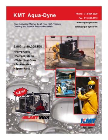
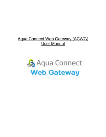
Manual System OperationDiagnostic MenuWhile the main objective of the Aqua Plus is to automate the operation of your pool/spa system, there may becertain times when you want to override the automatic operation and control the equipment manually. To operatethe pool equipment manually while keeping the automation active, perform the following procedures. Note that ifyou turn a relay on manually, it will remain on until either you turn it off manually, or the next time the programmedautomatic operation would normally turn that relay off. Example: the filter pump is programmed to run from 9:00Ato 5:00P daily. If you turn the filter pump on manually at 8:00PM, it will run continuously until the next day at5:00PM at which time it will turn off and follow the normal program from then on. Manually turning off a relayworks in a similar fashion.To enter the Diagnostic Menu, press the “Menu” button repeatedly until the display shows “DiagnosticMenu”. At this point, you can use either the “ ” or “ ” buttons to scroll through the various menu itemswhich are described below: 23.45Set Day and 6.75ATimeWednesday84 F3200PPM10:37P /- 23.45V is the voltage applied to the chlorinator cell /-6.75A is the current (amps) through the cell84ºF is the water temperature at the cell3200PPM is the “instant” salt level at this timeDisplayThis display will be shown only if the chlorinator is enabled. For the chlorinator to beoperating, several other things must be happening: the filter pump must be running, the flowswitch must be detecting flow, the chlorinator setting must be set greater than 0%, the watertemperature at the cell must be between 50ºF and 140ºF, and the salt level must be within theoperating range. If any of these conditions are not met, the chlorinator diagnostic displaywill tell you the reason. It’s possible to have more than one reason, in which case after yourectify what was displayed the first time, a second display will appear.Pool/Spa ButtonSalt ter PumpValve 3IndicatorIf the current (amps) display is 0.00A, then the chlorinator is operating normally but is in theoff part of its normal operating cycle. Simply press either the “ ” or “-“ key to start a newcycle.(On/Off)HeaterOption ValveCheck SystemCheck SystemIndicatorPool/Spa ServiceMenuFilter Service ButtonLightsThe Aqua Plus periodically reverses the polarity of the voltage applied to the cell in order toautomatically clean off any calcium deposits. It is important that you check the chlorinatoroperation in both polarities. To do this, press either the “ ” or “-“ buttons and the chlorinatorwill turn off, wait for 15 seconds and then turn on in the opposite polarity.(On/Off)LightsAux 1Aux 2Aux 1(On/Off)If a conventional or solar heater is operating, it is likely that the temperature of the water atthe cell is higher than the pool/spa water temperature displayed on the Aqua Plus defaultdisplay.Aux 2(On/Off)(main display only)Menu and NavigationButtonsFilter PumpInstant Salt3200 PPM ( save)if AQL-CHEM is usedpH 7.5ORP 700 mV(On)(On)Freeze Protection: This function protects the pool, plumbing, and equipment against freeze damage. If FreezeProtection is enabled and the AIR temperature sensor falls below the preset freeze protection temperature (seeFilter Configuration), the Aqua Plus will turn on the filter pump to circulate the water.External Input Interlock:If enabled, this function will force the filter pump off when the external input is active. External Input Interlock willhave precedence over Freeze Protection for Filter output.3Press to load the “Instant Salt” into the averaged salt displayMove to previous/next menu itemThis display will be shown only if the chlorinator is enabled. This display shows “InstantSalt” or “Instant Minerals” (if Chlor. Config. is set for “Display Minerals”). The “InstantSalt” is calculated based on the voltage, current (amps), and water temperature at the cell.This is different than the “average salt” value which is displayed as part of the default menu.There are a number of reasons why instant and average salt readings may differ. Some ofthese include salt having just been added to the pool and not yet thoroughly mixed, calciumbuildup on the cell, and the cell aging.Single Speed Filter Pump: If the pump is currently off, press the FILTER button to turn on the pump. Pressing theFILTER button again will turn off the pump. However, if there is a heater in the system, and it is operating, and the“Heater Cooldown” feature is enabled (Configuration Menu) then: when you press the FILTER button to turn offthe filter, only the heater will turn off, the Filter LED will flash and the display will indicate “Heater Cooldown”. Atthis point the filter pump will automatically turn off after 5 minutes of heater cooldown operation. If you want tooverride the heater cooldown, simply press the FILTER button again to turn off the filter pump.Two Speed or Variable Speed Filter Pump: If the pump is currently off, simply press the “FILTER” button to turnon high speed operation of the filter pump. The “Filter” LED will illuminate continuously. Pressing the “FILTER”button again will switch to low speed operation and the “FILTER” LED will flash. Note that if the pump has been offfor more than 30 seconds, it will run at high(est) speed for 3 minutes regardless of selection. This high speedoperation helps allow the pump to prime and establish normal water flow.Press to switch chlorinator operation to opposite polarity (15 second delay)Move to previous/next menu itemFlow SwitchFlowNo functionMove to previous/next menu itemThis display will be shown only if sensing is enabled. This display shows both pH and ORPlevels/status when chemistry sensing is enabled via the Chemistry Configuration Wizard(requires the use of AQL-CHEM Sensing Kit). The Aqua Plus will refer to these levels todetermine how much chlorine to generate (ORP) and, if using an AQL-CHEM2 dispense kit,how much CO2 or acid to dispense (pH). Refer to the AQL-CHEM manual for specificinformation about these levels as well as the recommended ranges.No functionMove to previous/next menu itemThis display will be shown only if the chlorinator is enabled. The current status of the flowswitch is displayed. There is a short delay when transitioning from flow to no-flow and alonger delay on the transition from no-flow to flow. The delay time is displayed.32
No Cell Power -- If no chlorinator cell power is detected on the printed circuit board. Check Flow Switch -- If the flow switch input is invalid. Cell Power Error -- If a chlorinator cell power error is detected on the printed circuit board. Cell Missing -- If the chlorinator is enabled but no cell is detected. Pool Bridge Comm -- If variable speed is selected for the Pool Filter and the VSC interface is not responding. Pool VSC Comm -- If variable speed is selected for the Pool Filter and the Hayward VSC is not responding. Pool VSC Err: x -- If variable speed is selected for the Pool Filter and the Hayward VSC is indicating anderror. x is the same decimal error displayed by the VSC itself. CSM Comm Error: -- If Chemistry Sensing is enabled and the Chemistry Sense Module (CSM) is notresponding.Lights, Aux1 and Aux2 OutputsStandard Relay: Manual operation of all 3 relays is identical. Assuming that the relay is currently off, simply pressthe appropriate button to turn on the relay. If the relay does not turn on, it probably is due to the “interlock” feature(which was set up in the Configuration Menu) being activated that requires the filter pump to be running and thevalves to be in the pool-only position. This protects pumps and other equipment from possible damage. If thecontrolled output is on, pressing the appropriate button again will turn off the relay. Manual turn off is disabled if the“Freeze Protection” feature is enabled and the air temperature is less than the selected freeze temperature threshold.Dimmer Relay: If Lights or an Aux output is configured as a dimmer, pressing the corresponding button willgenerate a temporary display which shows the dimmer output level (Off - On 100%). Pushing the “ ” or “-”button changes the level in increments of 20%. When the desired output level is displayed, press the corresponding button again to turn off the display and return to normal operation. When the Lights or Aux output comes onagain (either manually or automatically), the dimmer output level will be the same as the last time that it was set.External Input Interlock:If enabled, this function will force the Lights or Aux off when the external input is active. External Input Interlockwill not have precedence over Freeze Protection for Lights and Aux outputs. pH Probe Error -- If the CSM indicates that there is a problem with the pH probe. pH Low - Check Feeder -- If a pH level of 6.9 or less is detected, check the feeder for proper operation pH High - Check Feeder -- If a pH level of 8.1 or higher is detected, check the chemical supply and thefeeder for proper operation pH Timeout - Check Feeder -- If the unit has been dispensing pH for more than the selected timeout withoutreaching the desired level. Check the chemical supply and the feeder. If both are OK, the timeout may need tobe increased. Press the “ ” button to reset the alarm and resume dispensing. pH Calibration Error -- When using the pH Calibration Wizard and the entered test result was different fromthe measured pH level by 1.0 or more. The pH probe may need to be cleaned or replaced. ORP Probe Error -- If the CSM indicates that there is a problem with the ORP probe. ORP Low - Check Chlor -- If an ORP level of 350mV or less is detected. Check the chlorinator for properoperation. ORP High - Check Chlor -- If an ORP level of 950mV or higher is detected. Check the chlorinator for properoperation. ORP High - Chlor Off -- If an ORP level of 950mV or higher is detected and the chlorine feed mode is ORPAuto Sensing, the chlorinator has been turned off. Check the chlorinator for proper operation. ORP Timeout -Chlor Off -- If the unit has been chlorinating for more than the selected sanitizer timeoutwithout reaching the desired level, the chlorinator has been turned off. Press the “ ” button to reset the alarmand resume chlorination. Ambient Sensor -- If the Aqua Plus internal temperature sensor is either an open or short circuit.For helpful troubleshooting information on any of these issues, go to the Diagnostic Menu and then scroll throughthe various items until you see the cause for the “CHECK SYSTEM” LED being illuminated.Pool/Spa ValvesPool-only or spa-only systems: The POOL/SPA button has no function.Pool and Spa systems without spa spillover: In pool-only mode, the left LED next to the POOL/SPA button isilluminated. Pressing the POOL/SPA button will switch the Aqua Plus to spa-only operation (right LED illuminated). Pressing the POOL/SPA button again will switch back to pool-only. Note that the filter pump will turn offwhile the pool/spa valves are turning.Pool and Spa systems with spa spillover: In pool-only mode, the left LED next to the POOL/SPA button isilluminated. Pressing the POOL/SPA button will switch the Aqua Plus to spa-only operation (right LED illuminated). Pressing the POOL/SPA button again will switch to spa spillover operation (both LED’s illuminated).Pressing the POOL/SPA button again will switch back to pool-only. Note that the filter pump will turn off while thepool/spa valves are turning.External Input Interlock:If enabled, this function will force the Valve off when the external input is active. External Input Interlock will nothave precedence over Freeze Protection for Valve outputsServiceThe main unit keypad has a SERVICE key. This button is used primarily during servicing of the pool equipment.If you want to completely disable the automatic operation and operate the system manually, you can put the systeminto Service or Service-Timed mode by pressing the SERVICE button. Pressing the SERVICE button once willswitch the system into service mode which means that all automatic functions are disabled, and the remote display/keypads are disabled (except for manual turn off for emergencies). The red SERVICE LED will be illuminated andthe Aqua Plus will remain in this mode of operation until manually taken out of service mode.Pressing the SERVICE button again will cause the Aqua Plus to switch to service-timed mode which is very similarto service mode, except that the Aqua Plus will automatically return to normal operation after 3 hours. Duringservice timed operation, the “Service” LED will flash and the time remaining will be displayed on the remotedisplay/keypad(s).Pressing the SERVICE button again, will return the Aqua Plus to normal (automatic) operation. See Troubleshooting/Diagnostic Information (page 30) for more information about the service modes.314
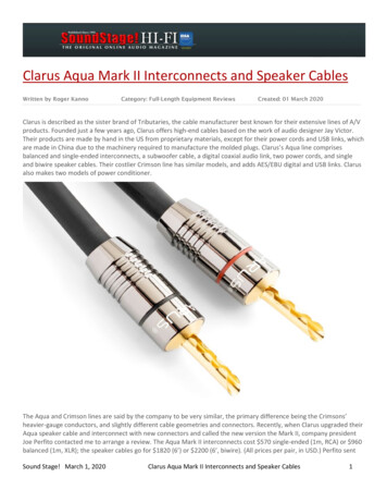
Automatic System OperationThe Aqua Plus controls most of your pool equipment automatically in order to minimize the time spent working onyour pool. Most of the pool equipment can be programmed to operate on a timeclock basis. In addition, thedesired pool and spa temperatures and pool and spa chlorinator settings can be programmed. This section willguide you on how to program the automatic operation for each function.The programming of automatic functions can be performed at either the main display/keypad located at the poolequipment pad or the in-home remote display/keypad.Using the programming buttonsThere are 5 buttons on each keypad that are used for programming (refer to diagram).DisplayTroubleshooting and Diagnostic InformationThe Aqua Plus provides 2 different tools to aid in troubleshooting any problems that may occur in your pool and/or spa system. The Service mode will allow you to disable automatic operation and manually control most of theequipment (the heater and general purpose Valve3 output are the exceptions). The Diagnostic Menu will providesome detailed information regarding system operation.While both of the features are primarily intended for the use of the professional service technician, their function isfully explained below. If you believe your system is not operating properly or have questions regarding the operation, call the Goldline Technical Service Department from Monday through Friday, 8AM to 8PM EST at 888921-7665.Service ModeThe main unit keypad has a SERVICE button that is used primarily during servicing of the pool equipment.If you want to completely disable the automatic operation and operate the system manually, you can put the systeminto Service or Service-Timed mode by pressing the “Service” button. Pressing the “SERVICE” button once willswitch the system into service mode which means that all automatic functions are disabled, the optional remotedisplay/keypads are disabled (except for manual turn off for emergencies). The outputs can be manually controlledby pressing the buttons on the local display/keypad. The red “SERVICE” LED will be illuminated and the AquaPlus will remain in this mode of operation until manually taken out of service mode.Salt Level3200ppmPool/SpaMenu ButtonSelect Desired Menu Service MenuFilterLightsAux 1 Aux 2Pressing the “SERVICE” button again will cause the Aqua Plus to switch to service-timed mode which is verysimilar to service mode, except that the Aqua Plus
Electrolytic Cell inspect & clean Refer to section in manual. TEST IDEAL RANGE ADJUSTMENT REQUIRED Drain and add water to decrease. . pool automation products as well as its Aqua Rite, Aqua Rite Pro, Aqua Plus and SwimPure chlorination products to be free of defects in materials and workmanship, under normal use and service, for a period of .