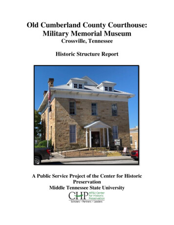
Transcription
SP624SP624Page 1 of 69STATERev. 03-17-15Rev. 08-27-15Rev. 12-7-15Rev. 5-16-16Rev. 5-14-18OFTENNESSEEJanuary 1, 2021SPECIAL PROVISIONREGARDINGRETAINING WALLSGeneral DescriptionThis Special Provision covers the design requirements, submittal of wall design drawings andsupporting calculations, materials, construction, measurement, and payment for earth retainingwalls. The scope of work for retaining wall construction includes, but is not limited to, thefollowing as required:1.2.3.4.5.6.7.8.9.10.11.12.13.14.All grading necessary for wall construction,Undercutting and backfilling of weak surficial zones, and orground improvement as required by plansTemporary Shoring/WallCompaction of wall foundationsGeneral and local dewatering as required for proper execution of the workConstruction of leveling padsFormwork, placement of reinforcing steel, placement and curing of concreteTexture coating or architectural treatmentPlacement of drainage materialsInstallation of pilingPlacement of soil reinforcing devicesPlacement and compaction of backfillPreparation and erection of wall unitsConstruction of any required caps, copings, or end sectionsAll items included in the construction of the retaining wall shall conformto this Special Provision, the Tennessee Department of TransportationStandard Specifications for Road and Bridge Construction, henceforth referredto as the Standard Specifications, American Society for Testing MaterialsStandards (ASTM), Federal Highway Administration (FHWA) TechnicalPublications, t h e c u r r e n t e d i t i o n o f t h e A A S H T O L R F D B r i d g eC o n s t r u c t i o n S p e c i f i c a t i o n s , and the current AASHTO LRFD BridgeDesign Specifications with interims, henceforth referred to as the AASHTOLRFD. The architectural treatment and/or texture finish of the walls shall bein accordance with the contract plans.
SP624SP624Page 2 of 69Design CriteriaThe design of all types of earth retaining walls shall be in accordance with thisSpecial Provision and the following Specifications as required:1.AASHTO LRFD Bridge Design Specifications with interims2.Publication no. FHWA-NHI-10-024, Mechanically Stabilized Earth Wallsand Reinforced Soil Slopes3.(FHWA Report No. FHWA-SA-99-018, 1999)Geotechnical EngineeringCircular No. 4, Ground Anchors and Anchored SystemsThe soil and/or rock properties and specific design values required for wall designare provided in the contract plans.Submittal Requirements for Contractor/Supplier Prepared Design PlansThe Contractor shall utilize the information contained on the Retaining WallConceptual drawing as well as information shown elsewhere in the plans (i.e. utilitysheets or traffic control/phasing sheets) to prepare his bid for the wall during theproject bidding process and to prepare wall design plans during the constructionof the project. The final design shall be submitted subsequent to contract awardand a minimum of sixty (60) days prior to start of wall construction and shall includedetailed design computations and all details, dimensions, quantities and cross sectionsnecessary to construct the wall. Acceptable wall types will be identified on theconcept drawing. Specific wall systems for the Acceptable Wall Types shall beselected from the Department’s Qualified Products List (QPL 38) in effect at time ofbid letting. In certain circumstances for a particular project, TDOT may elect toprovide a complete, detailed wall design in the contract plans. The Contractor shallnot bid for nor shall the Contractor submit plans for wall types and/or specific wallsystems not listed as an Acceptable Wall Type on the Retaining Wall ConceptualDrawing and related drawings. If a specific wall design is provided for in the contractplans, the Contractor shall not bid for or submit plans for other wall types or design.(See Section 8 for the limited conditions under which other wall types or designs maybe considered).The plans shall be prepared to include but not be limited to the following items:1. A plan and elevation sheet or sheets for each wall containing the following:a. An elevation view of the wall showing grades at the top of the wall, every50 feet along the wall and at all horizontal and vertical break points.Elevations at the top of leveling pads and footings, the distance along theface of the wall to all steps in the footings, and leveling pads, thedesignation as to the type of panel or module, the length, size and numberof tiebacks, nails, mesh or strips and all the distances along the face of thewall to where changes in length of the reinforcing elements occur and thelocation of the original and final ground line should be shown. TheContractor shall be responsible for field verifying original groundelevations.b. A plan view of the wall shall indicate the offset from the construction
SP624SP624Page 3 of 69c.d.e.f.g.h.centerline to the face of the wall at all changes in horizontal alignment, thelimit of the widest module, tiebacks, nails, mesh or strip and the centerlineof any drainage pipe which is behind, under, in front of or passes throughthe wall.Any general or special notes, standard or special drawings, or other uniqueprovisions required for construction of the wall.All horizontal and vertical curve data affecting wall construction.Cross sections showing limits of construction and in fill sections, limitsand extent of select granular backfill material placed above originalground.Limits and extent of reinforced soil volumeLimits and extent of any ground improvements as required by thecontract plans.Limits and extent of temporary shoring/retaining walls.2. Detailsa. All structural details including reinforcing bar bending details. Barbending details shall be in accordance with CRSI standards.b. All details for foundations and leveling pads, including details for steps inthe footings or leveling pads.c. Wall Elevation drawings shall delineate the changes in wall design heightwith corresponding changes in reinforcement type and/or lengths for thedesign section.d. For each delineated wall design segment the Applied Factored BearingLoad at both the Service and Strength Limit States shall be shown.e. All modules and facing elements shall be detailed. The details shall showall dimensions necessary to construct the elements, all reinforcing steel inthe element, and the location of reinforcement element attachment devicesembedded in the facing.f. All details for construction of the wall around drainage facilities, overheadsign footings, abutment piles or other obstructions shall be clearly shown.g. All details for connections to traffic barriers, coping, parapets, noise wallsand attached lighting shall be shown.h. All details for drainage behind wall or reinforced soil volume.i. If vehicular impact protection is required due to the wall system notsatisfying the minimal design requirements of Section 5.0, details of thebarrier wall and end terminals shall be shown on the Contractor/SupplierDesign plans for the proposed wall.3. Detailed design computations which clearly demonstrate compliance withdesign requirements provided in this specification.4. Limits of design responsibility, if any.5. Each design submittal shall include a detailed list of quantities for each wallunit. The quantities shall include but not be limited to: concrete cast in-place,pre-cast concrete, select backfill material, backfill material, reinforcing steel,
SP624SP624Page 4 of 69geomembrane/geogrid reinforcement, modular blocks, structural steel, prestressing steel, etc. If known, all materials sources shall be identified soacceptance and verification sampling and testing can be conducted. Allquantities listed are for informational purposes only and do not necessarilyconstitute a pay item or quantity . All retaining walls shall only be paid forunder the respective retaining wall bid item measured and described herein.6. The Contractor’s wall plans shall be signed, stamped and dated by aqualified registered Professional Engineer licensed in the State of Tennessee.7. Submittals and ApprovalFour sets of design drawings and detail design computations shall besubmitted to the Structures Division. The computations shall include adetailed explanation of any symbols and computer programs used in the designof walls. Structures Division will submit two of their four copies to theDivision of Materials and Tests.Each design drawing shall contain in the title block the project number,county, structure name, structure number, station and contract number. Designdrawings shall be submitted in sets with the drawing numbers runningconsecutively in each set, and if more than five (5) sheets in a set, shall beappropriately bound.All designs and construction details will be checked by the StructuresDivision and the Materials and Tests Division against the pre- approved designdrawings and procedures for that particular system. Review of the wallsubmittal will occur within 30 days of receipt. If there are design or plans issuesrequiring revisions then the Structures Division will inform the appropriateTDOT Construction Office and provide a listing of the required revisions.Depending on the required revisions the 30 day review timeframe may beextended. Approval of the detailed design and plans shall be made by theStructures Division and Materials and Tests Division. Notification to proceedshall be made by the Structures Division.After approval, the Contractor shall submit additional sets of the designdrawings (full size and half size) as determined by the Structures Divisionfor Departmental distribution. Also, an electronic copy of the design drawingsand detail design computations shall be submitted to the Structures Divisionand the Materials and Tests Division upon completion of the project.8. Other Submission RequirementsAs discussed in the previous sections, the Contractor shall bid for and,subsequently, (for the Contractor for which the project was awarded) prepareplans for and be prepared to construct the wall type(s) given on the RetainingWall Conceptual Drawing or, under special circumstances, the specific walltype and design as provided by in the Contract Plans. The Contractor awardedthe project may only under the circumstances discussed below request that a
SP624SP624Page 5 of 69wall type, wall system, or associated construction for a wall (i.e., foundationimprovement requirements, construction sequence requirements, etc.) bechanged, altered, or eliminated from those requirements set forth in the plans.The Contractor may request the Department consider a change in the walltype, specific system, and associated construction through the submission of aValue Engineering Change Proposal (VECP) unless the contract prohibitssubmission of a VECP. Furthermore, any conditions of a VECP, such as aminimum cost savings required by the contract must be followed. TheDepartment’s agreement to review a VECP for a retaining wall shall in noway imply subsequent acceptance of the VECP or any part thereof. Any costsassociated with preparation and submittal of a VECP shall be borne by theContractor and no construction scheduling changes or time delays shall becaused by the Contractor’s submission of the VECP and the Department’sreview of the VECP. If the proposed change involves a wall system not on theApproved Wall System list, then the contractor must coordinate with the systemsupplier to gain approval of the system and shall be aware of the approvalrequirements and time considerations for this approval process.The Contractor may request the Department consider a change in the walltype, specific system, and/or associated construction if the Contractordetermines that project conditions exist that substantially differ from thoseconditions upon which the decision to specify in the plans a particular walltype(s), wall system, or associated construction was made. An example ofthis would be where a soldier pile-lagging wall is specified as the only walltype due to right-of-way constraints not allowing for a typical wall type to bebuilt, then subsequently it is determined TDOT can acquire or has sufficientright- of-way available to make another wall type feasible.The request for consideration of changing of a wall type, system, or associatedconstruction shall be made in writing and be submitted to the ConstructionEngineer. The Construction Engineer will distribute the request to theRegional Construction Engineer, Structures Division, GeotechnicalEngineering Section, Design Division, and Right-of-Way Division, ifapplicable. The parties will review the request and provide recommendedaction (approval, rejection, alterations) to the Construction Engineer. Ifnecessary, a plans revision will be made. Note that the Contractor’ssubmission of a request does not imply acceptance by the Department and thatthe request process shall not be justification for a project schedule change ortime extension. The Department reserves the right to require the Contractor toconstruct the wall as shown in the plans if there are no conditions that existwhich render the contract plan wall requirement not constructible.The Contractor must provide documentation in the request to demonstrate thatthe proposed change does not in any way cause additional cost to the wall andassociated construction or to other aspects of the project. If the Contractorjudges that a change involving wall construction must be made due to differingsite conditions, the Contractor must follow procedures given in Sections 104.02and 104.03 of TDOT Standard Specifications for Road and
SP624SP624Page 6 of 69Bridge Construction.Requirements for retaining wall protection provided by the retaining wall systemWhen noted on the plans that a retaining wall is located in a hazard zone subject tovehicular impact, the Contractor shall be aware that retaining wall protection againstvehicular collision for the wall may be required. If the retaining wall facing meetsany one of the following criteria, an independent barrier wall shall be provided infront of the wall and included in the square foot cost of the wall:1. Any retaining wall facing that is constructed of non-reinforced concrete (castin-place concrete gravity walls are exempt from this requirement and do notrequire protection.2. Any dimension of a retaining wall facial panel that is less than 5’0” x 5’0” x6” thick reinforced panel.3. Any type of crib retaining walls.4. A cast in place reinforced facing that has a thickness less than 6 inches.Materials ApprovalThe materials used in the construction of the earth retaining walls shall conform tothis Special Provision and/or the Standard Specifications. Prior to delivery of anymaterial used in the retaining wall construction, the materials must be accepted inconformance with the specifications associated with the wall type being constructed.MaterialsUnless other otherwise stated in specific retaining wall specifications, the materialsused in the construction of earth retaining walls shall conform to the followingspecifications:1. Concrete Class “A” shall be in accordance with Section 604 of the StandardSpecifications.2. Concrete Class “D” Shall be in accordance with Section 604 of the StandardSpecifications.3. Reinforcing steel shall conform to ASTM A 615, Grade 60.4. The sources for all backfill material shall be approved in conformance withthe Standard Specifications before the material is delivered to the job site.Any select backfill material must be approved or tested for compliance priorto construction.5. Lifting hooks and threaded inserts shall be of the size indicated on the workingdrawings.6. When required, imbedded items must be galvanized in accordance withAASHTO M 232 or ASTM A 153.7. Acceptance of materials furnished for work will be in accordance with theTDOT “Procedures for the Sampling and Testing, and Acceptance ofMaterials and Products (SOP 1-1) and certified test reports as specified inSection 106 – Control of Materials supplemented by routine tests run by theDepartment as defined in the various applicable sections of the Standard
SP624SP624Page 7 of 69Specifications.8. Clearing and grubbing, removal of structures and obstructions, and excavationand undercutting shall be performed in accordance with the provisions ofSections 201, 202, and 203, respectively, of the Standard Specifications. Costof these items, however, shall be included in the square foot price bid forretaining walls as shown in contract plans.9. Reinforced Concrete Facing Panels - The panels shall be fabricated inaccordance with the TDOT Procedure for the “Manufacture and Acceptanceof Pre-cast Concrete Drainage Structures, Noise Wall panels, and Retainingwall panels.”10. Stone masonry shall be in accordance with Section 612 of the StandardSpecifications.11. All fabricated or precast retaining wall assemblies shall be selected from theTDOT’s Qualified Products List.All concrete, reinforcing steel, and backfill materials shall be tested at the specifiedfrequencies in accordance with the TDOT “Procedures for the Sampling and Testing,and Acceptance of Materials and Products (SOP 1-1)”.Method of MeasurementThe method of measurement shall be square foot area of the wall face, measured from thetop of footing (or bottom of wall for walls without footings) to the top of the wallexcluding any appurtenances in accordance with drawing number W-MSE-1 (in thisdocument). Appurtenances are defined herein as barriers, fences, sign supports, noisewall support posts, and other fixtures. Coping, caps, end sections and moment slabs willnot be considered appurtenances and are to be considered as part of the wall face.Basis of PaymentThe earth retaining wall, complete in place and accepted, shall be paid for at the contractsquare foot bid price. The bid price for walls shall include as required: grading andcompaction of the wall foundation, undercutting and backfilling of weak surficial zones,installation of ground improvement, footing excavation, presplitting, sheeting, shoring,drilling, piles, lagging, grouting, concrete, reinforcing steel, reinforcement strips or mesh,tie strips or rods, fasteners, connectors, wire mesh baskets, prefabricated modularcomponents, post tensioning, performance testing and evaluation, architectural treatmentand/or texture finish, drainage system, water-stops and joint sealing material, coping, caps,end sections, moment slabs, and all miscellaneous material and labor for the completeinstallation of the wall. If the contractor's design requires the use of select granularbackfill, the unit price bid for the wall shall be full compensation for any additionalbackfill costs due to the use of select backfill material.If required for retaining wall protection against vehicle impact, the cost of the barrier walland end terminals shall be included in the square foot cost of the wall.Additional area of wall required due to unforeseen foundation conditions or other reasonsand approved by the Engineer will be paid for on the basis of the unit price bid except asnoted below.The mechanically stabilized earth wall, complete in place and accepted as noted above,shall be paid for at the contract square foot bid price. No increase in unit price will be
SP624SP624Page 8 of 69paid for increases in wall height less than or equal to 10 feet as compared to the contractplans and wall heights. Wall height increases greater than 10 feet will be paid for bysupplemental agreement.The cast-in-place concrete cantilever or counterfort retaining wall, complete in place andaccepted shall be paid for at the contract square foot bid price except as noted below.If the actual driven quantity of concrete piles driven varies more than 10% from theestimated quantity based on the estimated lengths, an increase or decrease based on thecontract bid price, or in the absence of a bid item, a unit price of twenty eight (28)dollars, per linear foot of additional or reduced pile length will be added or deductedaccordingly from the price paid for the retaining wall. If the Engineer orders additionaltest piles, they will be paid for at the contract bid price, or in the absence of a bid item,a unit price of forty (40) dollars per linear foot. If the contractor changes friction piletypes or sizes, additional load test(s) may be required at the Engineer’s discretion and atthe contractor's expense.If the contractor uses a different type of pile than those that have estimated lengths shownon the contract plans, the price of the wall shall include all costs associated with piles andpile installation with no additional payment for any variation in pile lengths. All piletypes and pile driving procedures, lengths, and bearings shall be in accordance with theStandard Specifications and shall be approved by the EngineerThe contractor shall show the estimated quantity of point bearing steel piles on the designdrawings submitted for approval. If the actual quantity of steel piles driven differs morethan 10% from this approved quantity because of variation in the rock line, the cost of theretaining wall will be increased or decreased accordingly based on the contract bid price,or in the absence of a bid item, a unit price of thirty five (35) dollars per linear foot, forthe adjusted piling quantity .If the Engineer orders changes in the work which alters the surface area of the wallwithout increasing the height of the wall, payment will be increased or decreasedaccordingly based on the square foot bid price. If the Engineer orders changes in the workwhich increases the height of the wall, the unit price bid for the wall sections that wereincreased up to a maximum of 10 feet will be adjusted according the following tables.Adjustments exceeding 10 feet will be made by supplemental agreement.
SP624SP624Page 9 of 69RETAINING WALL COST ADJUSTMENT FACTORSLevel Backfill with Slope 3 : 1 (Run : Rise)Original Height (ft.)Height Increase (ft.)1 - 41.451.451.461.471.471.471.481.481.481.48RETAINING WALL COST ADJUSTMENT FACTORSLevel Backfill with Slope 3 : 1 (Run : Rise)Original Height (ft.)Height Increase (ft.)1 - 91.791.781.771.761.741.731.721.701.691.67
SP624SP624Page 10 of 69Specific Wall Construction and Materials RequirementsA. Cast-in-Place (CIP) Concrete Gravity Retaining Walls1.ConstructionThe construction of the wall shall be in accordance with this Special Provisionand the Standard Specifications.B. Cast-In-Place (CIP) Concrete Cantilever And Counterfort Retaining Walls1.ConstructionThe construction of the wall shall be in accordance with this Special Provisionand the Standard Specifications. If the use of piles is anticipated, the foundationinformation shown on the contract plans shall include the skin friction (Fs) andend bearing (Qb) values, or the location of the rock line. Based on thisinformation, estimated pile lengths shall be shown on the contract plans for fifty(50) and one hundred (100) tons ultimate bearing capacity for Size 1 concretefriction piles. The contractor shall estimate point bearing steel pile refusal lengthsbased on the given rock line information.Concrete friction piles shall be installed to provide a minimum factor of safety of2.0 if a load test is used and a minimum factor of safety of 3.0 if a load test is notused. Pile types, load test procedures, and driving equipment shall be inaccordance with the Standard Specifications and shall be approved by theEngineer. The number and location of test piles and load tests shall be approvedby the Engineer. Test pile lengths shall be ten (10) feet longer than the estimatedpile lengths. Test piles shall be driven in accordance with the StandardSpecifications, and shall be required at least every fifty (50) feet along the wall,unless otherwise approved by the Engineer. No pile shall be any farther thanfive hundred (500) feet from a load test, if a load test is used, unless otherwiseapproved by the Engineer. The length of production piles to be driven and therequired bearing based on the driving equation shall be determined by theEngineer based on the required design bearing, the results of the test piles andload tests (if used), and applicable safety factors. Driven pile lengths and finalbearings shall be approved by the Engineer.Point Bearing Steel Piles shall be driven to refusal. Pile tips shall be used whenindicated on the contract plans.All reinforcing steel projecting from footing into the wall in the back face (fillside) shall be epoxy coated.C. Concrete Crib Walls (See QPL 38 for Approved Manufacturer/Supplier)1.MaterialsThe following items are the construction materials requirements necessary forcrib wall design fabrication. All materials shall be approved prior to use. Pre-Cast Concrete Crib UnitsThe pre-cast crib units are to be made of Class D Portland cement concreteconforming to Section 604 of the Standard Specifications.
SP624SP624Page 11 of 69 Crib BackfillAll backfill material shall be tested prior to use and at the establishedfrequencies in the TDOT “Procedures for the Sampling and Testing, andAcceptance of Materials and Products (SOP 1-1)”. oThe crib backfill material shall consist of an AASHTO classifiedA-1-a, A-1-b, or A-3 soil with the additional requirement no morethan ten percent by weight pass the #200 sieve.oThe unit weight of the crib fill should be a minimum 115 lb. percubic foot.oFilter protection (geotextile) may be required.Backfill Behind the Crib Type StructureAll backfill material shall be tested prior to use and at the establishedfrequencies in the TDOT “Procedures for the Sampling and Testing, andAcceptance of Materials and Products (SOP 1-1)”.2.oIf a filter blanket is placed behind the wall, native soil may be usedas backfill behind the structure.oSelect fill, as defined in 4.2.1 of this document, can be used asbackfill behind the structure. The backfill unit weight must be aminimum of 115 pcf. An internal angle of friction can be assumedequal to 35 degrees.Fabrication of Precast Concrete Crib Units All pre-cast concrete shall be produced in an approved plant in accordancewith the TDOT Procedure for the “Manufacture and Acceptance of Precast Concrete Drainage Structures, Noise Wall panels, and Retaining wallpanels”.Out-of-state producers shall provide documentation of material qualitybefore the manufacture of any pre-cast products (i.e. aggregate qualityreports, cement/steel mill test reports, etc.)The fabricator shall provide two precast modular units to the Engineer forapproval.oThese approved precast modular units will serve as standardmodels. The finished exposed faces of the production precastmodular units should be similar to the exposed faces of the modelprecast modular units.oOne of the model precast modular units should be kept at theproduction plant for relative comparison to future modular units.The other model should be kept on the construction site forcomparison to the other delivered units. To assure uniform unit production steel forms must be used. The placement of reinforcing steel within the precast units should conformto the design placement shown in the shop drawings.
SP624SP624Page 12 of 69 Final acceptability of the precast units shall be determined on the basis ofcompression tests, production defects and tolerances, and visualinspection. The manufacturer shall furnish all sampling and testingfacilities. Section 604 of the Standard Specifications states the units shall be steamor moist cured until developing the specified compressive strength setforth in the shop drawings. Any unit not developing the specifiedcompressive strength shall be rejected. The precast units should not be delivered before samples have attained therequired compressive strength of 4,000 psi (f’c). Prior to shipment, the finished units are subject to visual inspection by theEngineer. Individual crib units may be rejected for any of the reasonslisted below.i.Variations in the ex
Special Provision and the following Specifications as required: 1. AASHTO LRFD Bridge Design Specifications with interims 2. Publication no. FHWA-NHI-10-024, Mechanically Stabilized Earth Walls and Reinforced Soil Slopes 3. (FHWA Report No. FHWA-SA-99-018, 1999)Geotechnical Engineering Circular No. 4, Ground Anchors and Anchored Systems