Transcription
T7Featuring The safe scrubbing alternativetHygenictFully Cleanable TanksServiceInformation331045Rev. 00*331045*
This manual provides service information for the TENNANT Model T7.This machine will provide excellent service. However, the best results will be obtained at minimumcosts if:D The machine is operated with reasonable care.D The machine is maintained regularly -- per the maintenance instructions provided.D The machine is maintained with TENNANT supplied or approved parts.Manual Number -- 331045Revision: 00Published: 12--04Tennant CompanyPO Box 1452Minneapolis, MN 55440Phone: (800) 553--8033 or (763) 513--2850www.tennantco.comFaST Foam Scrubbing Technology logo is a United States registered trademark of Tennant Company.Copyright E 2003 TENNANT, Printed in U.S.A.
Table of ContentsElectrical Troubleshooting Information . 1Commonly Used Electrical Symbols & Terms. 2Ladder Schematic . 3Wire Harness Group. 5Key OFF, Operator NOT on Seat. 9Key OFF, Battery Charger Plugged In . 10Key ON, Operator on Seat . 11Tank Level Sensors. 12Horn & Hour Meter Systems . 13Propel Forward System. 14Propel Reverse System. 15Braking System . 16Scrub Head & Squeegee Actuator Systems . 17Scrub Brush Motors System. 19Vacuum Fan System . 20FaST System. 21Conventional Solution System. 22LED Locations & Descriptions. 23Operational Modes & Interlocks . 24Diagnostic & Fault Alarms . 25Alarm Codes . 25High Current Faults . 25Diagnostic & Configuration Modes. 26Display Software Revision Mode . 27Self Test Mode . 28Input Display Mode. 29Manual Mode. 30Propel / Brake Diagnostics . 31Battery Select Mode & Voltage Levels. 32Battery Select Mode. 32Voltage Levels. 32Reverse Alarm & Propel Speed Select Modes . 33Reverse Alarm Select Mode . 33Propel Speed Select Mode . 33Inputs & Outputs Table. 34Torque Standard. 35Inch Fasteners. 35METRIC Fasteners. 37Nylon Insert Lock Nuts . 39Nut-Hex Light THIN . 39Wheel Bolt and Nuts. 40Wheel Bearing Adjustment. 40Tightening Nuts on Tapered Shafts . 41Shoulder Bolts . 42Taper Lockr Bushings . 43Sequence Tightening . 44i
ii
T7ELECTRICALTroubleshooting InformationBEFORE CONDUCTING TESTS:* Read and Follow ALL Safety Warnings and Precautions inOperator's Manual* Always use an ESD (Electrostatic Discharge) strap whenworking near the Control Board* Be cautious when working near Control Board – Batteryvoltage is always present, even with Key OFF* Always unplug Positive Battery Cable when removing orreplacing componentsDURING TESTS:* Call Technical Services if Diagnostic Time Exceeds One HourWith Unknown Cause or Course of ActionNOTE:Troubleshooting charts may be shown with optional equipment. The optional equipment may notbe specified in these charts. Some machines may not be equipped with all components shown.2005.01.05 T7ETI REV 001
Commonly Used Electrical Symbols & TermsNOTE: The term “NORMALLY” refers to the components’ “at rest” or “de-energized” position- Wires ConnectedTogetherNormally OpenSwitchWires NotConnected TogetherNormally OpenLimit SwitchPlug-inConnectionNormally OpenPush-Button SwitchNormally ClosedLimit SwitchNormally OpenBatteryCircuit BreakerNormally ClosedPush-Button SwitchFuseIndicates Movementfrom Normal PositionNormally ClosedM1Relay Coil(Part 1 of Relay)DiodeRelay Contacts (Part 2 of Relay)Solenoid (Valveor Actuator)Indicates Component inPosition Other than NormalXMotorWiring Standoff(Connection Point)Lamp(Light Bulb)Indicates Componentis EnergizedHorn or AlarmTerms & AbbreviationsBDI – Battery Discharge IndicatorDynamic Braking – A method of using the generating nature of an electric motor to slow the machineHall Effect – A voltage developed as a result of current flow in the presence of a magnetic fieldLED – Light Emitting DiodePM – Permanent MagnetPWM (Pulse Width Modulation) – A method of using controlled on/off times to regulate the voltage and current supplied to anelectrical deviceExample of Wiring Numbers & Colors:Wiring Color Codes(Unless otherwise marked)Right Most Digitof Wire Number012Color of Gray9White1 RED25713 BLK
T7 – Ladder Schematic (page 1 of 2)1234510210383
T7 – Ladder Schematic (page 2 of 2)1234541021038
T7 – Wire Harness Group (page 1 of 4)15
T7 – Wire Harness Group (page 2 of 4)16
T7 – Wire Harness Group (page 3 of 4)17
T7 – Wire Harness Group (page 4 of 4)28
T7 - Key OFF, Operator NOT on Seat 1 RED6 VDC- 6 VDC1 RED- 1 RED6 VDC- 6 VDC-13 BLK13 BLK13 BLKXSTANDOFF 4CHARGERPLUG1 REDv1 REDvM1B241 REDCB15AD3CONTROL BOARDEMERGENCYSTOP SWITCHS15MAINCONTACTOR24F1100 A554M1APIN J6-176344350 REDSW1LOGIC GROUNDD1642PIN J6-527GRNPIN J6-72627SW2SEATSWITCH26PIN J6-6CHARGER INTERLOCK21414CB215 A50 RED50 RED32ORGPIN J6-24KEYSWITCHX STANDOFF 242PIN J6-35PIN J6-13POST J11 POSPOST J7NEG-13 BLK13 BLKRIBBON CABLE CONNECTOR P6TOUCHPANELRIBBON CABLEWiring Color Codes(Unless otherwise marked)Right Most Digitof Wire Number01Color of y914TanWhite Battery Negativeor Logic Ground Battery Positiveor Positive Output9
T7 - Key OFF, Battery Charger Plugged In 1 RED6 VDC- 6 VDC- 1 RED1 RED6 VDC- 6 VDC-13 BLK13 BLK13 BLKSTANDOFF 4CHARGERPLUG1 REDv1 REDvM1B241 REDCB15AD3CONTROL BOARDEMERGENCYSTOP SWITCHS14544450 RED2M1A1463CHARGERSW1 INTERLOCK2642PIN J6-351450 RED27GRNSW2SEATSWITCHPIN J6-13POST J11 POSRIBBON CABLEWiring Color Codes(Unless otherwise rple8Gray9White Battery Negativeor Logic Ground Battery Positiveor Positive Output1027PIN J6-6TOUCHPANELColor of Wire32ORGPIN J6-24POST J7NEG-RIBBON CABLE CONNECTOR P6Right Most Digitof Wire NumberLOGIC GROUND42PIN J6-5PIN J6-726CB215 A50 REDPIN J6-17D163KEYSWITCHX STANDOFF 25MAINCONTACTOR2F1100 A51413 BLK13 BLKX
T7 - Key ON, Operator on Seat 1 RED6 VDC- 6 VDC- 1 RED1 RED6 VDC- 6 VDC-13 BLK13 BLK13 BLKXSTANDOFF 4CHARGERPLUG1 REDv1 REDvM1B1 RED4CB15AD32CONTROL BOARDEMERGENCYSTOP SWITCHS15MAINCONTACTOR24F1100 A55M1A634450 REDSW1LOGIC GROUND42PIN J6-527GRNPIN J6-7262627SW2SEATSWITCHPIN J6-6CHARGER INTERLOCK21414CB215 A50 RED50 RED32ORGPIN J6-24KEYSWITCHX STANDOFF 242PIN J6-35D1634PIN J6-17PIN J6-13POST J11 POSPOST J7NEG-13 BLK13 BLKRIBBON CABLE CONNECTOR P6TOUCHPANELIndicates Componentis EnergizedRIBBON CABLEWiring Color Codes(Unless otherwise marked)Right Most Digitof Wire Number01Color of urple8Gray914TanORIGHT SIDEDASH PANELIWhite Battery Negativeor Logic Ground Battery Positiveor Positive Output11
T7 – Tank Level SwitchesCONDITIONS: key ON6 VDC 1 RED-6 VDC - 1 RED1 RED6 VDC- 6 VDC-13 BLK13 BLK13 BLKSTANDOFF 4CHARGERPLUG1 REDv1 REDM1Bv1 RED4CB15AD32S155MAINCONTACTOR24F1100 ACONTROL BOARDEMERGENCYSTOP SWITCH5M1A42PIN J6-17D166RECOVERY TANKFULL SWITCHPIN J6-5PIN J6-20343LOGIC GROUNDPIN J6-354228SW3PIN J6-24KEYSWITCHX STANDOFF 2SW14450 RED2626PIN J6-6PIN J6-8CHARGER INTERLOCK21414CB215 A50 RED50 RED29PIN J6-13POST J11POST J7 POSNEG-42SW4SOLUTION TANKLOW SWITCH13 BLK13 BLKRIBBON CABLE CONNECTOR P6TOUCHPANELIndicates Componentis EnergizedRIBBON CABLEWiring Color Codes(Unless otherwise marked)Right Most Digitof Wire NumberTan01Pink2Brown3Orange4Yellow5GreenTank Level Switches Logic Chartswitchtank full tank empty switch OPEN switch CLOSEDSolution TankRecovery TankxxxxxSolution Tank Empty LED ONxxxindicatorSolution Tank Empty LED OFFRecovery Tank Full LED ONRecovery Tank Full LED OFF6Blue7Purple8GraySolution Tank Low Switch opens when solution tank is low9WhiteTank Level Switches are ALWAYS in the OPEN position with low orempty tank Battery Negativeor Logic Ground Battery Positiveor Positive Output1214Color of WireiRecovery Tank Full Switch closes when recovery tank is fullTank Level Switches are ALWAYS in the CLOSED position with full tankX
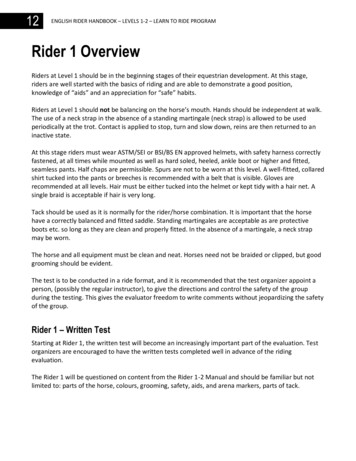
T7 – Horn & Hour Meter SystemsCONDITIONS: key ON, operator on seat, in motion OR Vacuum Fan running (for Hour Meter)1 RED6 VDC - 6 VDC- 6 VDC- 6 VDC-13 BLKSTANDOFF 4 Xv1 REDM1B2v1 RED4CB15AD32S155MAINCONTACTOR4F1100 ACONTROL BOARDEMERGENCYSTOP SWITCH54PIN J6-3564350 RED43SW1LOGIC GROUNDPIN J6-5PIN J6-24KEYSWITCHX STANDOFF 242D16M1APIN J6-1726PIN J6-10263042S2HORNSWITCHPIN J6-6CHARGER INTERLOCK21414CB215 A50 RED50 REDNOTE: Hour Meter is activeonly when propelling(forward or reverse), ORanytime Squeegee/Vacuum Fan is active14142323LS1HORN14140000021POST J11 POSPOST J7NEG-13 BLK13 BLKPIN J6-1521PIN J6-14H1HOUR METERRIBBON CABLE CONNECTOR P6TOUCHPANELIndicates Componentis EnergizedPIN J6-13LEFT SIDEDASH PANELRIBBON CABLEWiring Color Codes(Unless otherwise marked)Right Most Digitof Wire NumberColor of e8Gray9White Battery Negativeor Logic Ground Battery Positiveor Positive OutputHORNSWITCHRIGHT SIDEDASH PANELHorn pulses ON & OFF when Directional Switch is in REVERSEiHour Meter is ON only when propelling (forward or reverse), or anytimeSqueegee/Vacuum Fan is ONHorn pulses when a fault is detected (Directional Switch must be in FORWARDPosition) – refer to “Diagnostic/Beep Code” chart13
T7 – Propel Forward SystemCONDITIONS: key ON, operator on seat, propel pedal depressed1 RED6 VDC - 6 VDC- 6 VDC- 6 VDC-13 BLKSTANDOFF 4 Xv1 REDM1B2v1 RED4CB15AD32S155MAINCONTACTOR4F1100 ACONTROL BOARDEMERGENCYSTOP SWITCH54M1APIN J6-176334450 REDSW1LOGIC GROUNDD1642PIN J6-527GRNPIN J6-72627SW2SEATSWITCH26PIN J6-6CHARGER INTERLOCK21414CB215 A50 RED50 REDNOTE: Refer to the“Propel/Brake Diagnostics”page for more information2424 WHT25 BLKMTR1A14PIN J6-13POST J11 POSPIN J10-2PROPEL MOTOR25NOTE: Brake Solenoidis energized to releaseparking brake.14FORWARD251515PIN J6-27(Unless otherwise marked)13 BLK13 BLKPROPEL PEDALPOSITION SENSORGND 42U2HALLPIN J6-34 31 PROPEL EFFECTPOWERSIGNALSENSOR14FORWARDXPIN J6-22424235REVERSERIBBON CABLE CONNECTOR P6TOUCHPANELWiring Color CodesSW6PROPELDIRECTIONSWITCHLEFT SIDEDASH PANELRIBBON CABLEColor of e8Gray9White Battery Negativeor Logic Ground Battery Positiveor Positive Output Output that canChange Polarity14-PIN J10-1MTR1BBRAKESOLENOIDRight Most Digitof Wire NumberPOST J7NEG14Indicates Componentis Energized32ORGPIN J6-24KEYSWITCHX STANDOFF 242PIN J6-351414FORWARDDIRECTIONALSWITCHREVE RSERIGHT SIDEDASH PANELTypical Propel Motor Current Draw: 1 to 20 Amps in motion, higher at start-upiPropel Motor Voltage: 0 to 24 VDC - FORWARDApprox. 0 to 17 VDC - REVERSEPropel Motor is controlled by PWM (Pulse Width Modulation)The Propel Pedal Position HALL EFFECT Sensor sends a varying voltagesignal (1 to 4 Volts) to control board, based upon position of the propel pedal
T7 – Propel Reverse SystemCONDITIONS: key ON, operator on seat, propel pedal depressed1 RED6 VDC - 6 VDC- 6 VDC- 6 VDC-13 BLKSTANDOFF 4 Xv1 REDM1B2v1 RED4CB15AD32S155MAINCONTACTOR4F1100 ACONTROL BOARDEMERGENCYSTOP SWITCH54M1APIN J6-176334450 REDSW1LOGIC GROUNDD1642PIN J6-527GRNPIN J6-72627SW2SEATSWITCH26PIN J6-6CHARGER INTERLOCK21414CB215 A50 RED50 REDNOTE: Refer to the“Propel/Brake Diagnostics”page for more information2424 WHT25 BLKMTR1A14PIN J6-13POST J11 POSPIN J10-2PROPEL MOTOR25NOTE: Brake Solenoidis energized to releaseparking brake.14REVERSE251515-PIN J6-2713 BLKFORWARDXPIN J6-22Wiring Color Codes(Unless otherwise marked)424235REVERSERIBBON CABLE CONNECTOR P6TOUCHPANEL13 BLKPROPEL PEDALPOSITION SENSORGND 42U2HALLPIN J6-34 31 PROPEL EFFECTPOWERSIGNALSENSOR14PIN J10-1MTR1BBRAKESOLENOIDRight Most Digitof Wire NumberPOST J7NEG14Indicates Componentis Energized32ORGPIN J6-24KEYSWITCHX STANDOFF 242PIN J6-35SW6PROPELDIRECTIONSWITCHLEFT SIDEDASH PANELRIBBON CABLEColor of e8Gray9White Battery Negativeor Logic Ground Battery Positiveor Positive Output Output that canChange Polarity1414FORWARDDIRECTIONALSWITCHREVE RSERIGHT SIDEDASH PANELTypical Propel Motor Current Draw: 1 to 20 Amps in motion, higher at start-upiPropel Motor Voltage: 0 to 24 VDC - FORWARDApprox. 0 to 17 VDC - REVERSEPropel Motor is controlled by PWM (Pulse Width Modulation)The Propel Pedal Position HALL EFFECT Sensor sends a varying voltagesignal (1 to 4 Volts) to control board, based upon position of the propel pedal15
T7 – Braking SystemCONDITIONS: key ON, operator on seat, brake pedal depressed1 RED6 VDC - 6 VDC- 6 VDC- 6 VDC-13 BLKSTANDOFF 4 Xv1 REDM1B2v1 RED4CB15AD32S155MAINCONTACTOR4F1100 ACONTROL BOARDEMERGENCYSTOP SWITCH54M1A42PIN J6-17PIN J6-35D1663342PIN J6-527GRN4450 REDSW1PIN J6-72627SW2SEATSWITCH26PIN J6-6CHARGER INTERLOCK21414CB215 A50 RED50 REDNOTE: Refer to the“Propel/Brake Diagnostics”page for more information1424 WHTMTR1A25 BLK24PIN J6-13POST J11 POSPOST J7NEGPIN J10-2PROPEL MOTORNOTE: Brake Solenoid is DEenergized to apply parkingbrake. Dynamic Braking willoccur before Brake Solenoid isde-energized.2525151415-13 BLK13 BLKBRAKE PEDALPOSITION SENSORGND 42U2HALLPIN J6-33 32 BRAKE EFFECTPOWERSIGNALSENSOR14PIN J10-1PIN J6-2714MTR1BBRAKESOLENOIDRIBBON CABLE CONNECTOR P6TOUCHPANELIndicates Componentis Energized32ORGPIN J6-24KEYSWITCHX STANDOFF 2LOGIC GROUNDLEFT SIDEDASH PANELRIBBON CABLEWiring Color Codes(Unless otherwise marked)Right Most Digitof Wire NumberColor of e8Gray9White Battery Negativeor Logic Ground Battery Positiveor Positive Output1614i14The brake pedal position HALL EFFECT sensor sends a varying voltagesignal (1 to 4 Volts) to control board, based upon position of the brake pedalBrake Solenoid is DE-energized to apply brake.Dynamic Braking will occur before Brake Solenoid is de-energized.
T7 – Scrub Head & Squeegee Actuator Systems(page 1 of 2)CONDITIONS: key ON, operator on seat, forward travel, propel pedal depressed, One Step Scrub Button pressed1 RED6 VDC -6 VDC - 6 VDC- 6 VDC-13 BLKSTANDOFF 4 Xv1 REDM1B2v1 RED4CB15AD3255PIN J6-17PIN J6-35S1MAINCONTACTOR4F1100 ACONTROL BOARDEMERGENCYSTOP SWITCH5463342PIN J6-527GRN4450 REDSW126PIN J6-72627SW2SEATSWITCHPIN J6-6CHARGER INTERLOCK21414CB215 A50 RED50 RED181717MTR5SQUEEGEE ACTUATORNOTE: Actuator voltage switchespolarity when direction of actuatortravel changes (see next page formore information)19201832ORGPIN J6-24KEYSWITCHX STANDOFF 2LOGIC GROUNDD16M1A42PIN J6-13POST J11 POSPOST J7NEG-13 BLK13 BLKPIN J6-12PIN J6-919PIN J6-23MTR6SCRUB HEAD ACTUATOR20PIN J6-21RIBBON CABLE CONNECTOR P6Indicates Componentis EnergizedVacuum Fan/Squeegee ButtonOne StepScrub ButtonWiring Color Codes(Unless otherwise marked)Right Most Digitof Wire Number01TOUCHPANELLEFT SIDEDASH PANELRIBBON CABLEColor of Gray9White Battery Negativeor Logic Ground Battery Positiveor Positive Output Output that canChange PolarityPressing the “One Step Scrub Button” will lower the squeegee and scrub headiOnly one actuator will be energized at any given time – squeegee is loweredfirst, then the scrub headSqueegee actuator uses internal limit switches to stop travel in upward anddownward travelScrub head actuator travel is controlled by monitoring actuator current inupward travel and brush motor current in downward travelSqueegee actuator can also be operated by pressing the “Vacuum Fan/Squeegee Button”, without operating scrub brushes17
T7 – Scrub Head & Squeegee Actuator Systems(page 2 of 2)Actuator Voltage DataActuator Travel Direction Wire e18Gray17Purple18Gray19White20Tan19White20Tan " "" " " "" " NotesVoltage at actuator connector will beapprox. 24 VDC for 2 seconds, thenapprox. 12 VDC for 2 seconds for bothUP & DOWN travelVoltage at actuator connector will beapprox. 24 VDC for 4 secondsVoltage at actuator connector will beapprox. 24 VDC for 4 seconds, thenapprox. 11 to 12 VDC for 2 to 4 secondsPressing the “One Step Scrub Button” will lower the squeegee and scrub headiOnly one actuator will be energized at any given time – squeegee is loweredfirst, then the scrub headSqueegee actuator uses internal limit switches to stop travel in upward anddownward travelScrub head actuator travel is controlled by monitoring actuator current inupward travel and brush motor current in downward travelSqueegee actuator can also be operated by pressing the “Vacuum Fan/Squeegee Button”, without operating scrub brushes18
T7 – Scrub Brush Motors SystemCONDITIONS: key ON, operator on seat, forward travel, propel pedal depressed, One Step Scrub Button pressed1 RED6 VDC -6 VDC - 6 VDC- 6 VDC-13 BLKSTANDOFF 4 Xv1 REDM1B2v1 RED4CB15AD3255PIN J6-17PIN J6-35S1MAINCONTACTOR4F1100 ACONTROL BOARDEMERGENCYSTOP SWITCH5463342PIN J6-527GRN4450 REDSW126PIN J6-72627SW2SEATSWITCHPIN J6-6CHARGER INTERLOCK21414CB215 A50 RED50 RED8MTR277LEFT SCRUB BRUSH MOTOR10989MTR3RIGHT SCRUB BRUSH MOTOR1032ORGPIN J6-24KEYSWITCHX STANDOFF 2LOGIC GROUNDD16M1A42PIN J6-13POST J11 POSPOST J7NEG-13 BLK13 BLKPIN J8-1PIN J8-2PIN J8-3PIN J8-4RIBBON CABLE CONNECTOR P6Brush PressureButtonsIndicates Componentis EnergizedOne StepScrub ButtonTOUCHPANELLEFT SIDEDASH PANELRIBBON CABLEWiring Color Codes(Unless otherwise marked)Right Most Digitof Wire Number01Color of Gray9White Battery Negativeor Logic GroundiBrush Motor Current Draw: Approx. 10 to 20 Amps per motor, varying uponselected brush pressure settingBrush Motor Voltage: Approx. 18 VDC in Economy ModeApprox. 21.5 VDC in All Other ModesScrub Brush Motors are controlled by PWM (Pulse Width Modulation)Pressing the “One Step Scrub Button” will turn on the Scrub Brush Motors(after lowering squeegee and scrub head)Scrub Brush Motors will function only when propelling either forward or reverseScrub Brush Pressure is controlled by monitoring brush motor current Battery Positiveor Positive Output19
T7 – Vacuum Fan SystemCONDITIONS: key ON, operator on seat, forward travel, One Step Scrub Button pressed1 RED6 VDC -6 VDC - 6 VDC- 6 VDC-13 BLKSTANDOFF 4 Xv1 REDM1B2v1 RED4CB15AD3255PIN J6-17PIN J6-35S1MAINCONTACTOR4F1100 ACONTROL BOARDEMERGENCYSTOP SWITCH5463342PIN J6-527GRN4450 REDSW126PIN J6-72627SW2SEATSWITCHPIN J6-6CHARGER INTERLOCK21414CB215 A50 RED50 RED1232ORGPIN J6-24KEYSWITCHX STANDOFF 2LOGIC GROUNDD16M1A42PIN J6-13POST J11 POSPOST J7NEG-13 BLK13 BLK1111PIN J9-1MTR4VACUUM FAN12PIN J9-2RIBBON CABLE CONNECTOR P6Vacuum Fan/Squeegee ButtonIndicates Componentis EnergizedOne StepScrub ButtonTOUCHPANELLEFT SIDEDASH PANELRIBBON CABLEWiring Color Codes(Unless otherwise marked)Right Most Digitof Wire Number01Color of WireTanPink2Brown3Orange4Yellow5GreenVacuum Fan Motor Current Draw: Approx. 18 to 21 AmpsVacuum Fan Motor Voltage: Approx. 18 VDC in Economy ModeApprox. 21.5 VDC in All Other Modes6Blue7Purple8GrayPressing the “One Step Scrub Button” will activate Vacuum Fan9WhiteVacuum Fan can also be operated by pressing the “Vacuum Fan/SqueegeeButton”, without operating scrub brushes Battery Negativeor Logic Ground Battery Positiveor Positive Output20iVacuum Fan Motor is controlled by PWM (Pulse Width Modulation)
T7 – FaST SystemCONDITIONS: key ON, operator on seat, forward travel, propel pedal depressed, One Step Scrub Button pressed1 RED6 VDC -6 VDC - 6 VDC- 6 VDC-13 BLKSTANDOFF 4 Xv1 REDM1B2v1 RED4CB15AD3255PIN J6-17PIN J6-35S1MAINCONTACTOR4F1100 ACONTROL BOARDEMERGENCYSTOP SWITCH5463342PIN J6-527GRN4450 REDSW126PIN J6-72627SW2SEATSWITCHPIN J6-6CHARGER INTERLOCK21414CB215 A32ORGPIN J6-24KEYSWITCHX STANDOFF 2LOGIC GROUNDD16M1A42PIN J6-131450 RED50 RED14MTR72222POST J11 POSPOST J7NEG-13 BLK13 BLKPIN J6-25FaST PUMP MOTORRIBBON CABLE CONNECTOR P6FaST ButtonIndicates Componentis EnergizedOne StepScrub ButtonTOUCHPANELLEFT SIDEDASH PANELRIBBON CABLEWiring Color Codes(Unless otherwise marked)Right Most Digitof Wire Number01Color of GrayFaST system will operate ONLY if FaST LED is ON9WhiteSolution Volume Control Buttons will NOT operate & Solution VolumeControl LED’s will be OFF during FaST scrubbing Battery Negativeor Logic GroundiPressing the “One Step Scrub Button” will activate FaST Pump Motor ORSolution Solenoid Valve as Scrub Brush Motors engagePressing the FaST button will toggle from FaST scrubbing to Conventionalscrubbing Battery Positiveor Positive Output21
T7 – Conventional Solution SystemCONDITIONS: key ON, operator on seat, forward travel, propel pedal depressed, One Step Scrub Button pressed1 RED6 VDC - 6 VDC- 6 VDC- 6 VDC-13 BLKSTANDOFF 4 Xv1 REDM1B2v1 RED4CB15AD3255PIN J6-17PIN J6-35S1MAINCONTACTOR4F1100 ACONTROL BOARDEMERGENCYSTOP SWITCH54M1A6334450 REDSW1LOGIC GROUNDD1642PIN J6-527GRN26PIN J6-72627SW2SEATSWITCHPIN J6-6CHARGER INTERLOCK21414CB215 A32ORGPIN J6-24KEYSWITCHX STANDOFF 242PIN J6-131450 RED50 REDPOST J11 POSPOST J7NEG-13 BLK13 BLKSOL2141616PIN J6-4SOLUTION SOLENOID VALVERIBBON CABLE CONNECTOR P6Solution VolumeControl ButtonsIndicates Componentis EnergizedOne StepScrub ButtonTOUCHPANELLEFT SIDEDASH PANELRIBBON CABLEWiring Color Codes(Unless otherwise marked)Right Most Digitof Wire Number01Color of GrayConventional Solution system will operate ONLY if FaST LED is OFF9WhiteSolution Volume Control Buttons & LED’s will operate ONLY duringConventional scrubbing Battery Negativeor Logic Ground Battery Positiveor Positive Output22iPressing the “One Step Scrub Button” will activate FaST Pump Motor ORSolution Solenoid Valve as Scrub Brush Motors engagePressing the FaST button will toggle from FaST scrubbing to Conventionalscrubbing
T7 – LED Locations & Descriptions23
T7 – Operational Modes & InterlocksModeEntry SequenceIndicatorFunction Directional Switch Forward Directional Switch in Forward positionForwardForward movement of machine Propel Pedal Depressed Directional Switch Reverse Directional Switch in Reverse position Propel Pedal Depressed Horn Sounding continuously ON & OFF (except in"Hospital" mode)ReverseScrub ModeFaST Mode Press One Step Scrub Button One Step Scrub LED ON(ON) Press One Step Scrub Button One Step Scrub & FaST LED's ON(ON) Press FaST Button (ON) Press One Step Scrub ButtonConventional (ON)Solution Mode Press FaST Button (OFF) One Step Scrub & Solution Flow LED(s) ON FaST LED OFFDouble Scrub(no waterpickup) Press One Step Scrub Button One Step Scrub LED ON(ON) Press Vacuum Fan/Squeegee Vacuum Fan/Squeege LED OFFButton (OFF)Water pickup(no Scrub) Press Vacuum Fan/SqueegeeButton (ON)Low PowerMode Press Brush PressureDecrease (-) to one LED Press Solution Flow Decrease(-) to one LED Press Brush PressureLow Power Decrease (-) to one LEDMode w/ FaST Press FaST Button (ON)Solution Tank Solution Tank Empty (FloatSwitch Open)EmptyRecovery Tank Recovery Tank Full (FloatSwitch Closed)FullBatteryDischargedAccessoryMotor HighCurrent Fault24 Solution Flow LED's OFF One Step Scrub LED OFF Vacuum Fan/Squeegee LED ON Lower Brush Pressure (#1) LED ON; Middle (#2) &Upper (#3) LED's OFF Lower Solution Flow (#1) LED ON; Middle (#2) &Upper (#3) LED's OFF Lower Brush Pressure (#1) LED ON; Middle (#2) &Upper (#3) LED's OFF FaST LED ON (Solution Flow LED's OFF)Reverse movement of machineActivate Scrub Brush, Squeegee,Vacuum Fan & Solution FlowoperationsActivate FaST foam solution flow whenscrub and propel are engagedActivate Conventional solution flowwhen scrub and propel are engagedApply cleaning solution with no waterpickupCollect solution on floor with squeegee,without scrubbing floorReduce Scrub Brush and Fan speeds(to prolong battery life, reduce noise,lower water usage)Reduce Scrub Brush and Fan speeds(to prolong battery life, reduce noise,lower water usage) Solution Tank Empty LED ONDisable Scrub function (Operator canget an additional minute of operation byre-engaging scrub system with OneStep button) Recovery Tank Full LED ONDisable Scrub function (Operator canget an additional minute of operation byre-engaging scrub system with OneStep button) Battery voltage at or below full Red LED (on Battery Gauge) blinkingdischarge voltageDisable Scrub function (Operator canget an additional minute of operation byre-engaging scrub system with OneStep button) Fault LED ON and any one or more of the Controller sensed an Over following:Prevent damage to Scrub BrushCurrent condition in theLower Brush Pressure (#1) LED ON (Right Motor) Motors or Vacuum Fan Motor –Scrub Brush Motors orScrub function shuts offUpper Brush Pressure (#3) LED ON (Left Motor)Vacuum Fan MotorUpper Solution Flow (#3) LED ON (Vacuum Fan)
T7 – Diagnostic & Fault AlarmsAlarm CodesDirectionalSwitchModeBack-Up AlarmREVERSEPropel Interlock:Seat Switch ReleasedFORWARDPropel interlock:High Pedal DisablePropel Interlock:Throttle FaultPropel Interlock:Parking Brake FaultEntry SequenceAlarm SequenceDirectional switchplaced in REVERSEPropel Pedal depressedwith operator NOT onseatKey switch turned ONFORWARDwith PropelPedal engagedController sensedFORWARDan out-of rangeThrottle signalFORWARDFunctionHorn sounds 1 beep cycle (repeats)Alerts nearby persons of machinebackward movement (Note: Backup alarm will not sound whenmachine is placed in "Hospital"mode)Horn sounds 2 beep cycle (repeats)Prevents movement of machinewhen operator not in placeHorn sounds 4 beep cycle (repeats)Horn sounds 5 beep cycle (repeats)(Also FAULT and FaST LED's blink)Controller sensed an out- Horn sounds 6 beep cycle (repeats)of range(Also FAULT and Vacuum Fan/Brake signalSqueegee LED's blink)Prevents movement of machinewhen key
CONDITIONS: key ON, operator on seat, in motion OR Vacuum Fan running (for Hour Meter) 22 2 30 42 PIN J6-35 LOGIC GROUND 42 PIN J6-10 LS1 HORN H1 HOUR METER 14 14 21 RIGHT SIDE DASH PANEL HORN SWITCH M1B M1A 00000 NOTE: Hour Meter is active only when propelling (forward or reverse), OR anytime Squeegee/ Vacuum Fan is active S2 HORN SWIT .