Transcription
SPECIFICATION AND DESCRIPTIONCITATION M2October 2015Revision AUnits 525-0900 to TBD
CITATION M2SPECIFICATIONAND DESCRIPTIONUNITS 525-0900 TO TBDOCTOBER 2015REVISION AC e ssna A irc raft C ompanyP.O. B ox 7 7 06W ic hita, Kansas 6 7 27 7 -7 7 06
CITATION M2INTRODUCTIONThis document is published for the purpose of providinggeneral information for the evaluation of the design, performance, and equipment of the Cessna Citation M2, Units525-0900 to TBD. This document supersedes all previousSpecification and Description documents and describesonly the Cessna Citation M2 Model 525, its powerplantsand equipment.Due to the time span between the date of this Specificationand Description and the scheduled delivery date of the Aircraft, Cessna reserves the right to revise the Specificationwhenever occasioned by product improvements, government regulations or other good cause as long as such revisions do not result in a material reduction in performance.For additional information contact:Cessna Aircraft CompanyP.O. Box 7706Wichita, Kansas 67277-7706Telephone: 316-517-6449Telefax: 316-517-6640In the event of any conflict or discrepancy between thisdocument and the terms and conditions of the PurchaseAgreement to which it is incorporated, the terms and conditions of the Purchase Agreement govern.WARNING: This product contains Halon 1211 and Halon 1301. Furthermore, the product was manufactured with 1-1-1Trichloroethane, substances which harm public health and environment by destroying ozone in the upper atmosphere.Oc tober 2015, Revision A1
CITATION M2TABLE OF CONTENTSCESSNA CITATION M2 SPECIFICATION AND DESCRIPTIONSECTION PAGE1.General Description .1.1Certification .1.2Approximate Dimensions .1.3Design Weights and Capacities .2.Performance .3.Structural Design Criteria .4.Fuselage .5.Wing .6.Empennage .7.Landing Gear .8.Powerplants .9.Systems .9.1Flight Controls .9.2Fuel System .9.3Hydraulic System .9.4Electrical System .9.5Pressurization and Environmental System .9.6Oxygen System .9.7Ice and Rain Protection .10.Avionics .10.1General .10.2Instrument and Control Panels .10.3Avionics .10.4Miscellaneous Cockpit Equipment .11.Interior .11.1General .11.2Standard Interior Configuration .11.3Baggage .12.Exterior .13.Additional Equipment .14.Emergency Equipment .15.Documentation and Technical Publications .16.Computerized Maintenance Record Service (CESCOM) .17.Limited Warranties .17.1Cessna Citation M2 Limited Warranty .11.2Williams FJ44 Limited Engine Warranty .18.Citation M2 Crew Training Agreement .FIGURE I — CITATION M2 EXTERIOR DIMENSIONS .FIGURE II — CITATION M2 INTERIOR DIMENSIONS .FIGURE III — CITATION M2 INSTRUMENT PANEL AND PEDESTAL LAYOUT .FIGURE IV — CITATION M2 STANDARD FLOORPLAN 2121212222222427451319Oc tober 2015, Revision A
CITATION M21. GENERAL DESCRIPTION1. GENERAL DESCRIPTION1.1 CERTIFICATIONThe Cessna Citation M2 is a low-wing aircraft with retractable tricycle landing gear and a T-tail. A pressurized cabinaccommodates a crew of two and up to six passengers.Two FADEC controlled Williams International Co., LLC(Williams) FJ44 turbofan engines are pylon-mounted onthe rear fuselage. Fuel stored in the wings offers generous range for missions typical of this class aircraft. Spacefor baggage is provided in the nose and tailcone.The Model 525 is certified to the requirements of U.S. 14CFR Part 23 including day, night, VFR, IFR, and flight-intoknown icing conditions. It is also certified for single pilotoperations. The Citation M2 is compliant with all RVSMcertification requirements. (Note: specific approval is required for operation within RVSM airspace; Cessna offersa no charge service to assist with this process.)Multiple structural load paths and system redundancieshave been built into the aluminum airframe. Metal bonding techniques have been used in many areas for addedstrength and reduced weight. Certain parts with non-critical loads such as the nose radome and fairings are madeof composite materials to save weight. The airframe design incorporates anti-corrosion applications and lightning protection.The Purchaser is responsible for obtaining aircraft operating approval from the relevant civil aviation authority.International certification requirements may include modifications and/or additional equipment; such costs are theresponsibility of the Purchaser.Cessna offers a third-party training package for pilots andmechanics, and various manufacturers’ warranties as described in this book. Cessna’s worldwide network of authorized service centers provides a complete source forall servicing needs.Oc tober 2015, Revision A3
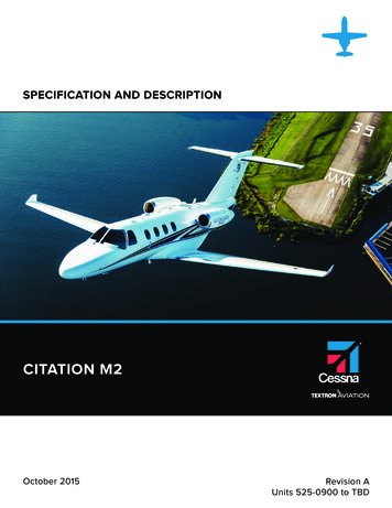
CITATION M21. GENERAL DESCRIPTION(CONTINUED)47 ft 3 in (14.39 m)18 ft 8 in (5.70 m)13 ft 0 in(3.96 m)13 ft 11 in(4.24 m)21 ft 11 in (6.68 m)42 ft 7 in (12.98 m)FIGURE I — CITATION M2 EX TERIOR DIMENSIONS4Oc tober 2015, Revision A
CITATION M21. GENERAL DESCRIPTION(CONTINUED)107 in(2.72 m)57 in(1.45 m)25 in(.64 m)58 in(1.47 m)20 in(.51 m)19 in(.48 m)11 in(.28 m)51 in(1.30 m)15 in(.38 m)29 in(.744824 in(.61 m)57 in(1.45 m)FIGURE II — CITATION M2 EX TERIOR DIMENSIONSOc tober 2015, Revision A5
CITATION M21. GENERAL DESCRIPTION(CONTINUED)1.2 APPROXIMATE DIMENSIONSOverall Height . 13 ft 11 in (4.24 m)Overall Length . 42 ft 7 in (12.98 m)Overall Width . 47 ft 3 in (14.39 m)WINGSpan (does not include tip lights) . 47 ft 0 in (14.33 m)Area .240.0 ft2 (22.30 m2)Sweepback (at 35% chord) . 0 degreesHORIZONTAL TAILSpan (tip to tip) . 18 ft 8 in (5.70 m)Area . 60.7 ft2 (5.64 m2)Sweepback (at 70% chord) .0 degreesVERTICAL TAILHeight . 6 ft 5 in (1.96 m)Area . 46.8 ft2 (4.35 m2)Sweepback (at 25% chord) . 49 degreesCABIN INTERIORHeight (maximum over aisle) . 57 in (1.45 m)Width (trim to trim) . 58 in (1.47 m)Length (forward pressure bulkhead to aft pressure bulkhead) . 15 ft 9 in (4.80 m)LANDING GEARTread (main to main) . 13 ft 0 in (3.96 m)Wheelbase (nose to main) . 15 ft 4 in (4.67 m)1.3 DESIGN WEIGHTS AND CAPACITIESMaximum Ramp Weight . 10,800 lb (4,899 kg)Maximum Takeoff Weight . 10,700 lb (4,853 kg)Maximum Landing Weight . 9,900 lb (4,491 kg)Maximum Zero Fuel Weight . 8,400 lb (3,810 kg)Standard Empty Weight* . 6,746 lb (3,060 kg)Useful Load . 4,009 lb (1,818 kg)Fuel Capacity (useable) at 6.70 lb/gal . 3,296 lb (1,495 kg)* Standard empty weight includes unusable fuel, full oil, standard interior, and standard avionics.6Oc tober 2015, Revision A
CITATION M22. PERFORMANCEAll performance data is based on the standard aircraft configuration, operating in International Standard Atmosphere (ISA)conditions with zero wind. Takeoff and landing field lengths are based on a level, hard surface, dry runway. Actual performance will vary with individual airplanes and other factors such as environmental conditions, aircraft configuration, and operational/ATC procedures.Takeoff Runway Length . 3,250 ft (991 m)(Maximum Takeoff Weight, Sea Level, ISA,Balanced Field Length per Part 25, 15 Flaps)Climb Performance . . . . 25 min to 41,000 ft (12,497 m)(Maximum Takeoff Weight, Sea Level, ISA)Maximum Altitude .Maximum Cruise Speed ( 3%)41,000 ft (12,497 m). 400 KTAS (741 km/hr) at 460 mph(Mid-Cruise Weight, 31,000 ft (9,449 m), ISA)NBAA IFR Range (100 nm alternate) ( 4%) .1,300 nm (2,408 km, 1,496 mi)(Maximum Takeoff Weight, Full Fuel, Optimal Climband Descent, Maximum Cruise Thrust at 41,000 feet)Landing Runway Length . . 2,590 ft (789 m)(Maximum Landing Weight, Sea Level, ISA, per Part 25)Certified Noise LevelsTakeoff . . 73.5 EPNdBSideline . . . . . .85.2 EPNdBLanding . . . 88.5 EPNdBOc tober 2015, Revision A7
CITATION M23. STRUCTURAL DESIGN CRITERIAThe Citation M2 airframe is conventional in design, incorporating aluminum alloys, steel and other materials as appropriate.Engineering principles using multiple load paths, low stress levels and small panel size are incorporated in the primary structure. Design maneuver limit load factors are -1.52 Gs to 3.8 Gs. Ultimate loads are defined as 1.5 times the limit loads. Thestructure supports a nominal maximum cabin pressure differential of 8.5 psi (.59 bar).Limit SpeedsVMO at Sea Level to 30,500 ft (9,296 m) . 263 KIAS (487 km/hr, 303 mph)MMO at 30,500 ft (9,296 m) and above . Mach 0.71 (indicated)Flap Extension SpeedsVFE 0 to 15 Extension . 200 KIAS (370km/hr, 230 mph)VFE 15 to 35 Extension . 161 KIAS (298 km/hr, 185 mph)Landing Gear Operating and Extended SpeedsVLO (retracting) .175 KIAS (324 km/hr, 201 mph)VLO (extending) .186 KIAS (344 km/hr, 214 mph)VLE .186 KIAS (344 km/hr, 214 mph)4. FUSELAGEThe Model 525 fuselage has a constant circular cross section and is attached to the wing without any cutouts for thespar. A dropped aisle from just behind the cockpit throughthe lavatory makes moving about the cabin easier. Thekeyed cabin door is located on the forward left-hand side ofthe fuselage. It has 12 locking pins and two pressure sealsand is hinged forward with a folding two-step entry stairmounted just inside the entrance. A plug-type emergencyexit is located on the aft right-hand side of the cabin. Framing assemblies surround the main door opening, emergency exit, and windshields to provide structural continuity.The aft fuselage houses the major components of the hydraulic, environmental, electrical distribution, flight control,and engine fire extinguishing systems. A baggage compartment is also located in the tailcone. External access to boththe equipment and the baggage area is provided througha baggage door on the lower left-hand side of the aft fuselage and removable exterior panels.The nose section includes a generous baggage compartment from which the avionics bay, oxygen bottle, and windshield alcohol supply are accessible. Behind the compositeradome is the high-resolution weather radar antenna andprocessor.8Oc tober 2015, Revision A
CITATION M25. WINGThe straight wing design of the M2 incorporates a naturallaminar flow airfoil. The wing structure is a three spar design with a shallow drop in the center section to permit attachment of the fuselage without interruption of the cabincross-section. Five degrees dihedral contributes to lateralstability.The wing leading edges are anti-iced using engine bleedair. Aluminum fairings blend the wing and fuselage for minimum drag. The landing lights consist of industry proven OSRAM LED technology. The wing tips include LED positionand anti-collision lights and static wicks.Integral fuel tanks are located in each wing. Control surfaces on the wing include outboard ailerons, wide span flapswith a lift-dump feature, and upper and lower surface speedbrakes. The left-hand aileron incorporates a trim tab.6. E M P E N N A G EThe empennage section is a T-tail design with a one-piecehorizontal stabilizer. The horizontal stabilizer’s leading edgeis equipped with pneumatic de-ice boots. The rudder andthe elevators have pilot-controlled trim tabs. A tail logo lightis standard with a red LED ground recognition light mounted on the top.7. L A N D I N G G E A RThe main and nose landing gear each use a single wheelassembly. The landing gear retraction system is electricallycontrolled and hydraulically actuated and takes less than 6seconds to cycle. Each main gear is a trailing link type andretracts inboard into the wing. The nose gear retracts forward into the fuselage nose section and, when retracted, isenclosed by doors. The nose wheel has a chined tire for water and slush deflection. Emergency landing gear extensionis accomplished by manual release of the uplocks for freefall followed by use of the pneumatic blow-down system.cally steered by the rudder pedals to 20 degrees either sideof center. For ground handling maximum deflection of thenosewheel is 95 degrees either side of center.Multiple disc anti-skid brakes are installed on the main gearwheels. An independent, electrically driven hydraulic system provides the power for braking with a pneumatic system for back-up. Anti-skid protection is available at speedsabove 12 knots.The landing gear may be extended at speeds up to 186KIAS. A warning horn will sound with the gear retracted ifairspeed is below 130 KIAS and either throttle is retardedbelow approximately 85% N2. The nose gear is mechani-Oc tober 2015, Revision A9
CITATION M28. POWERPLANTSTwo Williams FJ44 turbofan engines are installed, one oneach side of the rear fuselage in easily accessible nacelles.This engine is a 2.58:1 bypass, twin-spool design with 3compression stages and 3 turbine stages and produces1,965 pounds (8.74 kN) of takeoff thrust at sea level, staticconditions, flat rated up to 72 F (22 C).The FJ44 engine incorporates a modular design and multiple borescope ports for easier maintenance and inspections. Engine overhaul is required at 3,500 hour intervals. Acontinuous loop fire detection system monitors the nacellearea to detect and warn if a fire occurs. A fire extinguishingsystem is supplied.Dual channel Full Authority Digital Engine Controls (FADECs)provide automation and efficiency in engine management.Detents in the throttle quadrant for takeoff (TO), climb (CLB),high speed cruise (CRU) give pilots the optimal power settings for each phase of flight based on ambient conditions.The system also provides time-limited dispatch (TLD) anddiagnostics. Electrical power for the FADECs comes fromengine driven permanent magnet alternators (PMAs) rectified to DC. There are two PMAs mounted to each engine. Inthe event that both PMAs fail on one engine, the FADEC onthat side will draw from main DC power.9. SYSTEMS9.1 FLIGHT CONTROLSDual flight controls are provided consisting of control wheelcolumns, adjustable rudder pedals, brakes and mechanicalnose wheel steering. Pushrod, bellcrank, sector, and cablesystems are used to actuate the rudder, elevator, and ailerons. Corrosion resistant stainless steel cables are used inall primary and secondary systems.The 60 degree position, or ground flaps, is for lift dump andincreased drag only during landing and will automaticallycause the speed brakes to deploy. Speed brakes extendabove and below each wing and may be extended in flightat any speed. However, they will automatically retract anytime either engine’s throttle lever is in a high thrust position.The flaps and the speed brakes are electrically controlledand hydraulically actuated.Trim wheels installed on the pedestal control mechanicaltrim tabs for the left aileron, elevators and rudder. The elevator trim also has an electric actuator controlled by switcheson each pilots’ control wheel. A yaw damper system in thetail works with the autopilot to augment stability at high altitudes, however, it is not required for dispatch. An integralcontrol lock below the pilot’s panel holds the rudder, elevators, ailerons, and throttles during storage.9.2 FUEL SYSTEMWide span flaps are controlled by a handle on the pedestalwith detents at 15, 35, and 60 degrees. Any intermediateposition from zero to 35 degrees may be selected in flight.One electric boost pump in each tank sump delivers fuelduring engine start, fuel transfer, and as activated by lowfuel pressure. Each engine has an engine driven fuel pump10The M2 has two integral fuel tanks, one per wing, providinga total of 3,302 pounds (1,497 kg) of usable fuel. Systemoperation is fully automatic throughout the normal flightprofile with each engine receiving fuel from its respectivewing tank. Fuel is heated through an oil heat exchanger andanti-ice additives are not required.Oc tober 2015, Revision A
CITATION M29. SYSTEMS(CONTINUED)and a fuel delivery unit (FDU) controlled by the respectiveFADEC to deliver high pressure fuel to the engine. Some ofthat high pressure fuel from the FDU is routed back to a motive flow ejector pump in each fuel tank sump to generatethe low pressure fuel supply required by the FDU and by theone motive flow scavenge pump per tank located near eachsump. Fuel may be transferred from tank to tank as needed.A vented surge tank is integrated near each wing tip.switch panel and the indications are displayed on the MFDEIS window for voltage and generators amperage. Left andright circuit breaker panels are positioned on the cockpitsidewall within easy reach of each pilot. A junction box is accessible through the aft baggage compartment. The battery,with quick disconnect, is positioned just left of the baggagecompartment door behind an easy access panel. An externalpower receptacle is provided below the left engine pylon.Fuel levels are monitored by six passive capacitance probesper wing and one dual channel signal conditioner for accurate quantity indications which are shown on the multi-function display. Refueling is accomplished through over wingfiller ports with flush mounted caps.A sealed lead acid 24V, 16a-hr auxiliary battery is installed inthe nose over the landing gear well. During normal operation the battery works in conjunction with the primary shipsbattery to allow for all aircraft systems, including avionics, tobe powered on during engine starts. The auxiliary battery isalso used to provide additional battery capacity during emergency operation.9.3 HYDRAULIC SYSTEMThe hydraulic system is an open-center design providing1,500 psi (103.4 bar) on demand to operate the landing gear,speed brakes, and flaps. Two engine-driven pumps, onelocated on each engine, supply hydraulic pressure. Eitherpump can supply enough pressure and flow to operate thesystem. An independent hydraulic system, driven by an electric motor, operates the wheel brakes and anti-skid system,and charges the emergency accumulator.9.4 ELECTRICAL SYSTEMThe M2 electrical power generation and distribution systemfeatures traditional parallel bus architecture designed to provide 600 amperes at 28.5 volts DC from two engine driven300 ampere starter/generators. One 44 ampere-hour nickelcadmium battery is used for initial engine starts and serves asa limited backup to the generators.Each generator is connected to a remote digital generatorcontrol unit (GCU) in the tailcone. The two GCUs are connected to each other to allow proportionate load sharing. Ifone generator becomes disabled in flight, the vapor cycleair conditioning system, if in use, and the interior electricalequipment, will automatically load shed to prevent overloading the remaining generator. All other systems are suppliedby the remaining generator through the respective main andcrossfeed busses.A 500 watt inverter supplies 110 volt AC power to three outlets: one in th
CITATION M2 SPECIFICATION AND DESCRIPTION UNITS 525-0900 TO TBD OCTOBER 2015 REVISION A Cessna Aircraft Company P.O. Box 7706 Wichita, Kansas 67277-7706