Transcription
SANDIA REPORTSAND2018-9199Unlimited ReleasePrinted August 21, 2018Opal: A Centralized Memory Manager forInvestigating Disaggregated MemorySystemsV.R. Kommareddy and A. AwadSecure and Advanced Computer Architecture Research GroupUniversity of Central FloridaOrlando, FL 32816vamseereddy8@Knights.ucf.edu, amro.awad@ucf.eduC. Hughes and S.D. HammondCenter for Computing ResearchSandia National LaboratoriesAlbuquerque, NM 87185{chughes, sdhammo}@sandia.govPrepared bySandia National LaboratoriesAlbuquerque, New Mexico 87185 and Livermore, California 94550Sandia National Laboratories is a multimission laboratory managed and operated by National Technology andEngineering Solutions of Sandia, LLC., a wholly owned subsidiary of Honeywell International, Inc., for theU.S. Department of Energy’s National Nuclear Security Administration under contract DE-NA0003525.Approved for public release; further dissemination unlimited.
Issued by Sandia National Laboratories, operated for the United States Department of Energyby National Technology and Engineering Solutions of Sandia, LLC.NOTICE: This report was prepared as an account of work sponsored by an agency of the UnitedStates Government. Neither the United States Government, nor any agency thereof, nor anyof their employees, nor any of their contractors, subcontractors, or their employees, make anywarranty, express or implied, or assume any legal liability or responsibility for the accuracy,completeness, or usefulness of any information, apparatus, product, or process disclosed, or represent that its use would not infringe privately owned rights. Reference herein to any specificcommercial product, process, or service by trade name, trademark, manufacturer, or otherwise,does not necessarily constitute or imply its endorsement, recommendation, or favoring by theUnited States Government, any agency thereof, or any of their contractors or subcontractors.The views and opinions expressed herein do not necessarily state or reflect those of the UnitedStates Government, any agency thereof, or any of their contractors.Printed in the United States of America. This report has been reproduced directly from the bestavailable copy.Available to DOE and DOE contractors fromU.S. Department of EnergyOffice of Scientific and Technical InformationP.O. Box 62Oak Ridge, TN 37831Telephone:Facsimile:E-Mail:Online ordering:(865) 576-8401(865) /bridgeAvailable to the public fromU.S. Department of CommerceNational Technical Information Service5285 Port Royal RdSpringfield, VA 22161(800) 553-6847(703) v/help/ordermethods.asp?loc 7-4-0#onlineNT OF EMENRTGYERDEPATelephone:Facsimile:E-Mail:Online ordering: EDERU NITIC A STA TES OF AM2
SAND2018-9199Unlimited ReleasePrinted August 21, 2018Opal: A Centralized Memory Manager for InvestigatingDisaggregated Memory SystemsV.R. Kommareddy1 , C. Hughes2 , S. Hammond2 , and A. Awad11 SACA2 CenterResearch Group, University of Central Florida, Orlando, FL 32816for Computing Research, Sandia National Laboratories, Albuquerque, NM 87185AbstractMany modern applications have memory footprints that are increasingly large, driving systemmemory capacities higher and higher. Moreover, these systems are often organized where the bulkof the memory is collocated with the compute capability, which necessitates the need for messagepassing APIs to facilitate information sharing between compute nodes. Due to the diversity ofapplications that must run on High-Performance Computing (HPC) systems, the memory utilization can fluctuate wildly from one application to another. And, because memory is located in thenode, maintenance can become problematic because each node must be taken offline and upgradedindividually.To address these issues, vendors are exploring disaggregated, memory-centric, systems. In thistype of organization, there are discrete nodes,reserved solely for memory, which are shared acrossmany compute nodes. Due to their capacity, low-power, and non-volatility, Non-Volatile Memories(NVMs) are ideal candidates for these memory nodes. This report discusses a new component forthe Structural Simulation Toolkit (SST), Opal, that can be used to study the impact of using NVMsin a disaggregated system in terms of performance, security, and memory management.3
This page intentionally left blank.
Contents1Introduction72Opal Component9Integrating Opal in Simulated Systems . . . . . . . . . . . . . . . . . . . . . . . . . . . . . . . . . . .12Opal Configuration . . . . . . . . . . . . . . . . . . . . . . . . . . . . . . . . . . . . . . . . . . . . . . . . . . .14Example Opal Configuration . . . . . . . . . . . . . . . . . . . . . . . . . . . . . . . . . . . . . . . . . . .14Opal Requests . . . . . . . . . . . . . . . . . . . . . . . . . . . . . . . . . . . . . . . . . . . . . . . . . . . . . .16Memory Allocation Policies . . . . . . . . . . . . . . . . . . . . . . . . . . . . . . . . . . . . . . . . . . .17Communication Between Nodes . . . . . . . . . . . . . . . . . . . . . . . . . . . . . . . . . . . . . . . .173Evaluation194Conclusion23References245
List of Figures1.1An example of a disaggregated memory system. The system has several nodes(SoCs) where each node may have its own internal memory but share externalmemory. . . . . . . . . . . . . . . . . . . . . . . . . . . . . . . . . . . . . . . . . . . . . . . . . . . . . . . . . . . .72.1A simulated system that uses Opal for centralized memory management. . . . . . . . .102.2Implementing access control for direct access scheme. . . . . . . . . . . . . . . . . . . . . . . .112.3Implementing access control for virtualized system memory. . . . . . . . . . . . . . . . . . .122.4Example configuration . . . . . . . . . . . . . . . . . . . . . . . . . . . . . . . . . . . . . . . . . . . . . . . .163.1Disaggregated memory system performance in instructions per cycle for differentmemory allocation policies by varying number of nodes and number of sharedmemory pools . . . . . . . . . . . . . . . . . . . . . . . . . . . . . . . . . . . . . . . . . . . . . . . . . . . . . .20Comparing performance of disaggregated memory system by varying differentmemory allocation policies . . . . . . . . . . . . . . . . . . . . . . . . . . . . . . . . . . . . . . . . . . . .213.26
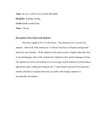
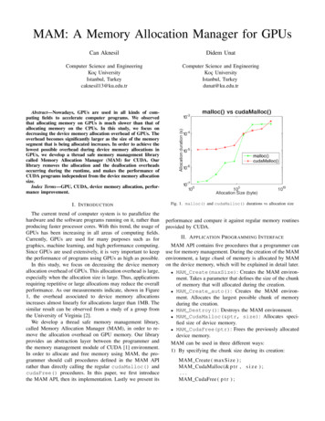
Chapter 1IntroductionWith the arrival of the big data era, the need for fast processing and access to shared memorystructures has never been as crucial as it is today. For better reliability, upgradability and flexibility,major vendors are considering designs that have disaggregated memory systems, which can beaccessed by a large number of processing nodes. The fact that such systems are disaggregatedallows upgrading memory, isolating malicious or unreliable nodes, and enables easy integration ofheterogeneous compute nodes (e.g. GPUs, FPGAs, and custom accelerators). To better understandhow a disaggregated memory system is organized,please refer to Figure 1.1, which depicts a sampledisaggregated memory system.Dense, power-efficient andpersistent memoryExternal Shared MemoryNVMRouterNVMRouterNVMRouterRouterExternal WorldLinkLocalMemoryNode 0LocalMemoryLocalMemoryNode 1Node 2Very fast interconnect (e.g.,GenZ-based, CCIX-based)LocalMemoryNode 3Fast but power-consumingmemory (e.g., DRAM)Figure 1.1: An example of a disaggregated memory system. The system has several nodes (SoCs) where each node may have its own internalmemory but share external memory.As shown in Figure 1.1, the nodes must access an off-chip network to access the externalmemory. Although local updates to external memory locations can be made visible to all othernodes, scaling the coherence protocol is challenging. While using directories could help, thereare still inherent design and performance complexities that can arise. One direction that vendorsare considering is the use of software to flush updates in local caches to the shared memory and7
make it visible to other nodes. One can think of it as having a lock around the shared data, andnot releasing it until all of the updates have been flushed to the external memory. Once the lockis released, the other nodes need to make sure they are reading the data from the external memoryrather than their internal caches. One way to do that is to use clflush after any reads or updates,which guarantees copies of that memory location are invalidated in the cache hierarchy. Other usecases include partitioning the memory carefully between nodes, where each node signals all of itsupdates and flushes. After which, an aggregator node can read the updated values from the externalmemory. In much simpler cases, such as a file containing a large social network graph where noupdates are expected to that graph (read-only), there is no need for special handling of accesses tothe graph.The Structural Simulation Toolkit (SST) [6] has been proven to be one of the most reliablesimulators for large-scale systems due to the scalability and modular design of its components.This makes SST the perfect candidate for simulating disaggregated memory systems at scale. Oneof the current limitations of SST is the lack of a centralized memory management entity thatcan correctly model page faults and requests for physical frames from the simulated machine.Such a limitation becomes more relevant when there are a large number of shared resources (e.g.memory pools). To address this problem and to facilitate research efforts in disaggregated memorysystems, a centralized memory management entity is proposed that can be used to investigateallocation policies, page placement, page migration [5], the impact of TLB shootdown [7, 1, 3],and other important aspects that are related to managing disaggregated memory systems. Thisreport describes Opal, a centralized memory management entity, and shows its efficacy using casestudies that can leverage the component.8
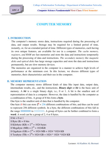
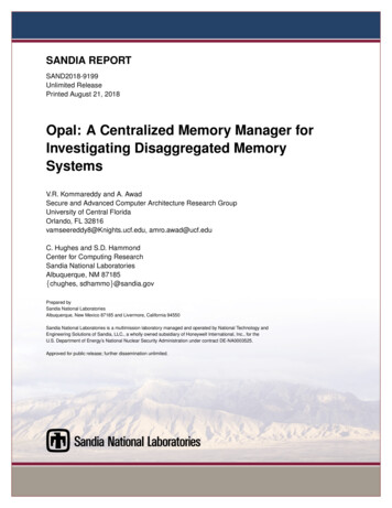
Chapter 2Opal ComponentOpal can be thought of as the Operating System (OS) memory manager, and in the case ofa disaggregated memory system, the system memory allocator/manager. In conventional systemswith single level memory, once a process tries to access a virtual address, a translation is triggeredto map the virtual address to a physical address. If a translation is not found, and the hardwarerealizes that either there is no mapping to that virtual address or the access permissions wouldbe violated, it triggers a page fault that is handled by the OS. The page fault handler maps thevirtual page to a physical page that is chosen from a list of free frames (physical pages). Oncea physical page is selected, its address is inserted in the page table along with the correspondingaccess permissions. Later, any accesses to that virtual address will result in a translation processthat concludes with obtaining the physical address of the selected page. Since SST aims for fastsimulation of HPC systems, it does not model the OS aspects of this sequence of events. However,the memory allocation process will have a major impact on performance for heterogeneous memory systems and disaggregated memory simply because of the many allocation policies that an OScan select from. Moreover, allocation policies are not well understood on disaggregated memorysystems, making it important to investigate them to discover the best algorithm or heuristics tobe employed for both performance and energy efficiency. To this end, Opal is proposed to facilitate fast investigation and exploration of allocation policies in heterogeneous and disaggregatedmemory systems.As shown in Figure 2.1, the Opal component should be connected to the processing elementsin SST and the hardware MMU unit. The main reason to be connected to processing elements isto pass allocation hints. For instance, if a process calls malloc or mmap with hints to whether thephysical frames should be allocated from local or remote memory, these hints should be recordedby Opal. While these calls do not immediately allocate physical pages, when a page is mapped,Opal can use the hints to decide where to allocate the physical page. Similarly, the hardware MMUunit should have links to Opal, so once a TLB miss and page table walk conclude with a page fault(unmapped virtual address), Opal will be sent a request for physical frame allocation, which willbe eventually mapped to the corresponding faulting virtual address.Before diving into the details of Opal, it is useful to understand the different ways a disaggregated memory systems can be managed. Exposing External Memory Directly to Local NodesIn this approach a local node OS (or Virtual Machine) sees both the local memory and exter9
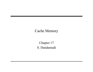
Figure 2.1: A simulated system that uses Opal for centralized memory management.nal memory. However, it needs to request physical frames from a central memory managerto be able to access external memory. To enforce access permissions and to achieve isolationbetween data belongs to different nodes/users, the system must provide a mechanism to validate the mappings and the validity of physical addresses being accessed by each node. Tobetter understand the challenges of this scheme, refer to Figure 2.2, which depicts differentoptions to implement access control on shared resources when external memory is directlyexposed to local nodes.In the Figure 2.2, Option 1 would be to check if the requesting node is eligible to access therequested address at the memory module level. This implementation requires a bookkeepingmechanism at the memory module level (or in the memory blade) to check the permission ofevery access. If the request is valid, it is forwarded to the memory device, otherwise eitherrandom data is returned or an error packet (access violation) is returned to the requestingcore. Since the external memory is shared between nodes, the system memory manager musthave a consistent view of allocated pages and their owning nodes. One way to implementrequesting external memory is through a device driver (part of local nodes’ OS) that canbe used to communicate (either through the network or predefined memory regions) withthe external memory manager. Option 2 is similar but instead of relegating the permissioncheck to the memory module, the router will have a mechanism to check if the accessedphysical addresses are granted to the requesting node. Finally, in Option 3 , an additionalbump-on-the-wire (ASIC or FPGA) can be added by the system integrator to check for the10
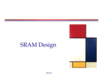
Figure 2.2: Implementing access control for direct access scheme.permissions of the requests coming out from each node. In all options, nodes will not beable to have direct access to the permission tables; only the system memory manager willhave such access. This can be guaranteed by encrypting requests with integrity and freshnessverification mechanisms. There are pros and cons of this implementation:3 Page table walking process is not modified and it is much faster than virtualizedenvironments (4 steps vs. 26 steps).3 Node-level memory manager optimizations and page migrations are feasible (unlikevirtualized environments).7 The operating system must be patched with a device driver to communicate withexternal memory manager.7 The centralized memory manager becomes a bottleneck if not scalable. Virtualizing External MemoryIn this approach, each node has the illusion that it owns all the system memory, which meansthe OS doesn’t need to be aware of the current state of the actual system physical memory.Figure 2.3 depicts the virtualized system memory scheme.As shown in the figure, a system translation unit (STU) must be added to support translationfrom the node physical address to the system physical address. The STU can be implementedas an ASIC- or FPGA-based unit that takes a physical address from the node and translatesit into the corresponding system physical address. If the address has never been accessed, anon-demand request mechanism is initiated by the STU to request a system physical page. The11
Figure 2.3: Implementing access control for virtualized system memory.STU might need to do a full system page table walk to obtain the node to system translation.Most importantly, the STU can only be updated through the system memory manager. Theadvantages and disadvantages of this scheme are:3 The OS does not need to be changed or patched.7 In addition to walking the node’s page table at the node level, the STU will need towalk the system level page table.7 There is no guarantee of where the system physical pages that back up the nodephysical pages exist.Integrating Opal in Simulated SystemsAs discussed above, Opal must be connected to both a MMU unit (such as SST’s Samba) anda Processing Element (such as SST’s Ariel). To allow this, any PE core or MMU unit can havea link that connects to their respective ports in Opal – mmuLink n and coreLink n, respectively.For example, port coreLink 0 can be connected to port opal link 0 for Ariel. For Samba, portmmuLink 0 can be connected to port ptw to opal0.Opal expects a minimum of two types of requests to be received through Samba and Ariel links– location hints and allocation requests. Hints originate from processing elements where mmapand malloc preferences are passed to Opal, which will attempt to satisfy them during on-demand12
Table 2.1: SST Modules UsedModuleCPUMMUNVMNetworkDescriptionArielSamba [2]Messier [4]Merlinallocation. This is similar to libNUMA malloc hints, which are recorded and used later by thekernel at the time of on-demand paging. Allocation requests come from the page table walkerwhen the accessed virtual page has never been mapped. This resembles minor page faults and ondemand paging on the first access to virtual pages in real systems. Apart from these two requests,Opal also accepts TLB shootdown and shootdown acknowledgment events from Samba units usingthe Samba to Opal link.Table 2.2: Opal ParametersParameterDescriptionclockfrequency of Opal componentmax instmaximum instructions processed in a cycle.num nodesnumber of nodesnode i coresnumber of cores per nodenode i clockfrequency of each node.node i latencylatency to access Opal component per nodenode i allocation policy memory allocation policy per nodenode i memorylocal memory specific information per node (parameters shown inTable 2.3)shared mempoolsnumber of shared memory pools to maintain shared memoryshared mem.mempool i global memory specific information per shared memory pool (parameters shown in Table 2.3)SST has modular designs for different hardware components. Currently Opal and the disaggregated memory model in SST work with specific modules, shown in Table 2.1. Opal uses Arielto model CPUs, Samba [2] to simulate memory management units (MMUs), Messier [4] for NVMmemory, and Merlin for networking.Table 2.3: Memory Pool ParametersParameterstartsizeframe sizemem techDescriptionstarting address of the memory poolsize of the memory pool in KB’ssize of each frame in memory pool in KB’s (equivalent to page size)memory pool technology (0 : DRAM, 1 : NV M)13
Opal ConfigurationOpal should be configured with component-specific, node-specific and shared memory-specificinformation as shown in Table 2.2. Component-specific information includes clock frequency,maximum instructions per cycle, etc.Node-specific information includes the number of nodes, the number of cores per node, clockfrequency, network latency to the Opal component, node memory allocation policy as explained insection 2 and local memory information.Shared memory-specific information includes the number of shared memory pools and therespective memory pool parameters. Both per-node local memory and per-shared memory poolparameters are related to memory and they are explained separately in Table 2.3. Each of theseparameters should be appended with memory related parameters shown in Table 2.2. Table 2.3describes the memory pool specific parameters. Each memory pool, either shared or local needs astarting address, size of the pool, frame size or page size and memory technology of the pool.Example Opal ConfigurationopalParams {"clock""max inst""num nodes""shared on emory.size""node0.memory.frame size""node0.memory.mem tech""node1.cores""node1.clock""node1.allocation emory.size""node1.memory.frame size""node1.memory.mem tech""node2.cores""node2.clock""node2.allocation 2000,0,#2us#in KB#2us#in KB#2us
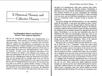
"node2.memory.size""node2.memory.frame size""node2.memory.mem tech""node3.cores""node3.clock""node3.allocation emory.size""node3.memory.frame size""node3.memory.mem tech""shared mem.mempool0.start""shared mem.mempool0.size""shared mem.mempool0.frame size""shared mem.mempool0.mem type""shared mem.mempool1.start""shared mem.mempool1.size""shared mem.mempool1.frame size""shared mem.mempool1.mem type""shared mem.mempool2.start""shared mem.mempool2.size""shared mem.mempool2.frame size""shared mem.mempool2.mem type""shared mem.mempool3.start""shared mem.mempool3.size""shared mem.mempool3.frame size""shared mem.mempool3.mem type":::::::::::::::::::::::::::16384,#in KB4,0,8,"2GHz",1,2000,#2us0,16384,#in KB4,0,001000000,4194304,#in KB4,1,101000000,4194304,#in KB4,1,201000000,4194304,#in KB4,1,301000000,4194304,#in KB4,1,}According to the example configuration, the clock frequency of Opal is 2GHz (”clock” :”2GHz”). In every cycle Opal can serve up to 32 requests (”max inst” : 32). The system has4 nodes (”num nodes” : 4) with a private memory each and shared global memory is divided into 4memory pools (”shared mempools” : 4). Each node has 8 cores (”node0.cores” : 8) and clock frequency of 2GHz (”node0.clock” : ”2GHz”). Private memory size is 16MB (”node0.memory.size” :16384) beginning at address 0 (”node0.memory.start” : 0). Memory technology of private memories in all the nodes is DRAM (”node0.memory.mem tech” : 0) with a frame size or page sizeof 4KB (”node0.memory. f rame size” : 4). Network latency to communicate with Opal is 2 micro seconds (”node3.latency” : 2000). Total global or shared memory is 16GB, which is divided into 4 memory pools each of 4GB (”shared mem.mempool0.size” : 4194304). Starting address of shared memory pool 0 is 001000000 (”shared mem.mempool0.start” : 001000000) whichis equivalent to local memory(16MB) 1, and memory pool 1 starting address is 101000000(”shared mem.mempool1.start” : 101000000) which is equal to starting address of shared memory pool 0 shared memory pool 0 size . Figure 2.4 depicts starting address of each memory poolfrom which size of each memory pool can be deduced. Each shared memory pool is of NV M type(”shared mem.mempool0.mem type” : 1) with 4KB frames (”shared mem.mempool0. f rame size”: 4). The memory allocation policy used for all nodes is the alternate memory allocation policy15
Shared memory (16GB)cpu/coresnode 0local memory16MB (DRAM)(000000-FFFFFF)mmucpu/coresOpal(memory allocator)Allocate fromlocal memoryAllocate fromshared memorynode 1local memory16MB (DRAM)(000000-FFFFFF)mmucpu/coresnode 2local memory16MB (DRAM)(000000-FFFFFF)Memory pool 04GB (DRAM)(001000000-100FFFFFF)Memory pool 14GB (DRAM)(101000000-200FFFFFF)Memory pool 24GB (NVM)(201000000-300FFFFFF)mmucpu/coresnode 3local memory16MB (DRAM)(000000-FFFFFF)Memory pool 34GB (NVM)(301000000-400FFFFFF)mmuFigure 2.4: Example configuration(”node0.allocation policy” : 1), which is explained in Section 2.Opal RequestsSeveral request types are handled and addressed in Opal: hints from the core, page faults frommemory management unit, TLB shootdown and shootdown acknowledgement requests.1. Hints: mmap and malloc requests are used to reserve space in the memory for future use.These requests, are sent to Opal by the core. Opal stores the requests as hints for memoryallocation.2. Page fault requests: Page fault requests need to be allocated memory. Allocation of memoryfrom local memory or shared memory is decided based upon the hints provided by the coreand the memory allocation policy. For every page fault request, Opal searches for any hintsassociated with the page. If hints are available, memory is allocated according from thespecified memory region. If no hint is found, memory is allocated based on the allocationpolicies. Memory allocation policies are explained in section 2.3. TLB shootdown: Nodes in disaggregated memory systems can benefit by migrating pagesfrom global memory to local memory. Opal has the capability to migrate pages from localmemory to shared memory and vise versa. Whenever pages are migrated, a TLB shootdownis initiated to invalidate the respective pages in all the cores in the nodes.4. Shootdown acknowledgement: The MMU component, which maintains TLB units, sends ashootdown acknowledge event to Opal after invalidating the addresses during a TLB shootdown event.16
Memory Allocation PoliciesVarious memory allocation policies are implemented in our design and are discussed below.1. Local memory first policy: Local memory is given more priority than shared memory. Localmemory is checked first and if there is no spare capacity then shared memory is checked. Ifshared memory is spread into different memory pools, then the memory pool is chosen randomly from among the available memory pools with enough space. If none of the memorypools have spare capacity,then an error message is thrown. This memory allocation policycan be chosen by setting the ”allocation policy” parameter of a node to 0.2. Alternate allocation policy: Memory allocation alternates between local and shared memoryin a round-robin fashion. For example, the first request will be allocated from local memory;the second request from shared memory; the third request from local memory; and so on.If there are multiple shared memory pools then requests alternate between the pools – thefirst request will be allocated from local memory; the second request from shared memorypool-0; the third request from local memory; the fourth request from shared memory pool-1;the fifth request from local memory; etc. This memory allocation policy can be chosen bysetting ”allocation policy” parameter of a node to 1.3. Round-robin allocation policy: Similar to the alternate allocation policy, round-robin alternates requests except that it includes all of the available pools in the queue rather than havinga nested policy. For example, if there are two shared memory pools then the first request willbe allocated from local memory; the second request will be allocated from shared memorypool-0; the third request will be allocated from shared memory pool-1; the fourth from localmemory; etc. This memory allocation policy can be chosen by setting ”allocation policy”parameter of a node to 2.4. Proportional allocation policy: Memory is allocated proportionate to the fraction of totalmemory that each memory provides. If local memory size is 2GB and shared memory sizeis 16GB, then for the 1st memory allocation request, memory is allocated from local memory and then for the next 8 memory requests memory is allocated from shared memory insequential order. For 10th memory request, memory is allocated from local memory and soon. This memory allocation policy can be chosen by setting ”allocation policy” parameterof a node to 3.Communication Between NodesOpal also supports communicating between nodes. Nodes can communicate with one anotherby sending hints with same f ileID to Opal using Ariel ariel mmap mlm and ariel mlm malloccalls. Opal checks if the received f ileID is registered with any memory. If it is, then the specificpage index is sent to the requesting node. If the f ileID is not registered with any memory page, thenmemory is allocated based on the requested size. The allocated memory region is now registered17
with the requester f ileID. Nodes can shared information just by writing information to the specificpages. This reduces costly OpenMPI calls to share information between nodes.18
Chapter 3EvaluationOpal was evaluated by studying the performance of a system with varying number of nodes,amount of shared memory and memory allocation policies. Performance is calculated in terms ofinstructions per cycle (IPC); IPC of all cores is averaged to get the system IPC.Table 3.1 describes the configuration of the system used to evaluate the design. We used 2 coresper node, a local memory of 2GB for each node and a shared memory of 16GB. Each core in anode is configured to execute maximum of 100 million instructions. For simplicity we assume thateach node executes only one application, XSBench. To increase the size of the load, XSBench isset to have large size with 2 threads. It should be noted that for Figures 3.1 and 3.2, N indicates thenumber of nodes and SM indicates number of shared memory pools the shared memory is dividedinto. For example, N4 with SM2 indicates the disaggregated memory system has 4 nodes andshared memory is divided into 2 shared memory pools. Also, LMF indicates local memory firstmemory allocation policy, ALT is alternate memory allocation policy, RR is round robin memoryallocation policy, and PROP indicates proportional memory allocation policy.Table 3.1: System ConfigurationParameterNumber of cores in each nodemaximum instruction count per coreLocal memory sizeShared memory sizeNetwork LatencyApplication running in each nodeApplication optionsValue2100M2GB16GB20nsXSBench-s large -t 2Contention at shared memory contributes to the performance of disaggregated memory systems. The more the contention at the memory the more will be the delay in getting response frommemory. Based on this we explored different memory allocation policies proposed. They are
Opal can be thought of as the Operating System (OS) memory manager, and in the case of a disaggregated memory system, the system memory allocator/manager. In conventional systems with single level memory, once a process tries to access a virtual address, a translation is triggered to map the virtual address to a physical address.