Transcription
OLinuXino-MICROOpen-source single-board Linux computerUSER’S MANUALRevision K, March 2013Designed by OLIMEX Ltd, 2012All boards produced by Olimex LTD are ROHS compliant
OLIMEX 2012OLinuXino-MICRO user's manualDISCLAIMER 2012 Olimex Ltd. Olimex , logo and combinations thereof, are registered trademarks of Olimex Ltd.Other product names may be trademarks of others and the rights belong to their respective owners.The information in this document is provided in connection with Olimex products. No license, expressor implied or otherwise, to any intellectual property right is granted by this document or in connectionwith the sale of Olimex products.The Hardware project is released under the Creative Commons Attribution-Share Alike 3.0 United StatesLicense. You may reproduce it for both your own personal use, and for commercial use. You will have toprovide a link to the original creator of the project http://www.olimex.com on any documentation or website.You may also modify the files, but you must then release them as well under the same terms. Credit can beattributed through a link to the creator website: http://www.olimex.comThe software is released under GPL.It is possible that the pictures in this manual differ from the latest revision of the board.The product described in this document is subject to continuous development and improvements. Allparticulars of the product and its use contained in this document are given by OLIMEX in good faith.However all warranties implied or expressed including but not limited to implied warranties ofmerchantability or fitness for purpose are excluded. This document is intended only to assist the reader in theuse of the product. OLIMEX Ltd. shall not be liable for any loss or damage arising from the use of anyinformation in this document or any error or omission in such information or any incorrect use of theproduct.This evaluation board/kit is intended for use for engineering development, demonstration, or evaluationpurposes only and is not considered by OLIMEX to be a finished end-product fit for general consumer use.Persons handling the product must have electronics training and observe good engineering practicestandards. As such, the goods being provided are not intended to be complete in terms of required design-,marketing-, and/or manufacturing-related protective considerations, including product safety andenvironmental measures typically found in end products that incorporate such semiconductor components orcircuit boards.Olimex currently deals with a variety of customers for products, and therefore our arrangement with the useris not exclusive. Olimex assumes no liability for applications assistance, customer product design, softwareperformance, or infringement of patents or services described herein.THERE IS NO WARRANTY FOR THE DESIGN MATERIALS AND THECOMPONENTS USED TO CREATE OLINUXINO. THEY ARE CONSIDEREDSUITABLE ONLY FOR OLINUXINO.Page 2 of 47
OLIMEX 2012OLinuXino-MICRO user's manualTable of ContentsDISCLAIMER. 2CHAPTER 1: OVERVIEW.51. Introduction to the chapter.51.1 Features.51.2 The OLinuXino family. 61.2 Target market and purpose of the board.61.3 Organization.7CHAPTER 2: SETTING UP THE OLINUXINO BOARD.82. Introduction to the chapter.82.1 Electrostatic warning.82.3 Requirements. 82.4 Powering the board.92.5 Prebuilt software.92.6 Using BitBurner.102.7 Building the Debian Linux image.112.8 How to blink the LED.132.9 How to setup Arch Linux distribution. 132.10 How setup the I2C, SPI, UART. 14CHAPTER 3: OLINUXINO BOARD DESCRIPTION.153. Introduction to the chapter.153.1 Layout (top view).163.2 Layout (bottom view).17CHAPTER 4: THE iMX233 MICROCONTROLLER. 184. Introduction to the chapter.184.1 The microcontroller.18CHAPTER 5: CONTROL CIRCUITY. 215. Introduction to the chapter.215.1 Reset.215.2 Clock. 215.3 Power supply circuit. 21CHAPTER 6: CONNECTORS AND PINOUT.236. Introduction to the chapter.236.1 Debugging interfaces. 236.1.1 UART debug.246.1.2 SJTAG debug. 246.1.3 Classic JTAG debug.25Page 3 of 47
OLIMEX 2012OLinuXino-MICRO user's manual6.2 SD/MMC slot.276.3 UEXT connector.286.4 CON1 and CON2 pads.296.5 USB HOST.336.6 PWR Jack.336.7 Headphones and line-in connector. 346.8 Composite video connector. 346.9 Boot mode positions.346.10 Jumper description.356.10.1 SCL SW/SCL HW and SDA SW/SDA HW.356.10.2 5V E.356.10.3 3.3V E jumper. 356.10.4 Boot mode selecting jumpers. 356.11 Additional hardware components.356.12 Accessories. 366.12.1 USB-SERIAL-CABLE-F.36CHAPTER 7: BLOCK DIAGRAM AND MEMORY. 377. Introduction to the chapter.377.1 Memory addresses. 377.2 Processor block diagram.387.3 Physical memory map. 39CHAPTER 8: SCHEMATICS.408. Introduction to the chapter.408.1 Eagle schematic.408.2 Physical dimensions.42CHAPTER 9: REVISION HISTORY AND SUPPORT. 439. Introduction to the chapter.439.1 Document revision. 439.2 Board revision. 459.3 Useful web links and purchase codes.469.3 Product support. 47Page 4 of 47
OLIMEX 2012OLinuXino-MICRO user's manualCHAPTER 1: OVERVIEW1. Introduction to the chapterThank you for choosing the OLinuXino single board computer from Olimex! This documentprovides a user’s guide for the Olimex OLinuXino-MICRO board. As an overview, this chaptergives the scope of this document and lists the board’s features. The differences between themembers of the OLinuXino family are mentioned. The document’s organization is then detailed.The OLinuXino development board enables code development of applications running on themicrocontroller i.MX233, manufactured by FreeScale Semiconductor.OLinuXino is an open-source, open-hardware project and all documentation is available to thecustomer.1.1 Features iMX233 ARM926J processor at 454Mhz64 MB RAMSD-card connector for booting the Linux imageTV PAL/NTSC video output1 USB High Speed Hostthree Buttons2x30 pin GPIO for connection of other hardwarePCB dimensions: 3.00'' x 1.70'' (76.2mm x 43.2mm)Nominal dimensions: 3.40'' x 1.70'' (86.4mm x 43.2mm)Page 5 of 47
OLIMEX 2012OLinuXino-MICRO user's manual1.2 The OLinuXino familyTable of AXIProcessoriMX233 @ 454MhziMX233 @ 454MhziMX233 @ 454MhzRam [MB]646464# USB hosts132100/150 MbitEthernet*No/WIFI option**No/WIFI option***Yes/WIFI option**GPIO connector60pins40pins40pins# Buttons322Reset buttonYesYesYesDC power supply5V6V-16V6V-16VDimensions3.40'' x 1.70''3.70'' x 2.65''3.70'' x 2.65''BreadboardingYesNoNoAudio IN connectorNoYesYesAudio OUT connector NoYesYesUEXT connectorNoYesYesBuilt-in USB hubNoYesYes* 100Mbit Ethernet for the wired network of OLinuXino-MAXI. 150Mbit for the WIFI following811.02n standard.** All three boards have the option to work with MOD-WIFI RTL8188, which is USB WIFImodem with RTL8188CU chip and can be purchased separately. MOD-WIFI RTL8188 can beconnected to any of the OLinuXino boards via the USB.*** OLinuXino-MINI has additional option of having RTL8188CU hardware mounted! If you wishRTL8188CU embedded in the device you should purchase OLinuXino-MINI-WIFI. Choosing theembedded WIFI option will leave your USB-HOSTs available for use.1.2 Target market and purpose of the boardThe boards from the OLinuXino family are ready to use, easy to setup and are suitable forembedded programming enthusiasts, Linux hobbyists, gadget fans and also professionals (since itslow cost makes it very good solution for application orientated embedded systems). The main usageof the board is software embedded development without the urge of understanding perfectly thehardware.The strong points of the boards are the processor speed, the mobility of the board and the low price.Page 6 of 47
OLIMEX 2012OLinuXino-MICRO user's manualCustomers have full access to the technical documentation of the board. The software is releasedunder General Purpose License and the board is considered open-hardware.1.3 OrganizationEach section in this document covers a separate topic, organized as follow:– Chapter 1 is an overview of the board usage and features– Chapter 2 provides a guide for quickly setting up the board and software notes– Chapter 3 contains the general board diagram and layout– Chapter 4 describes the component that is the heart of the board: the iMX233microcontroller– Chapter 5 is an explanation of the control circuitry associated with the microcontroller toreset. Also shows the clocks on the board– Chapter 6 covers the connector pinout, peripherals and jumper description– Chapter 7 shows the memory map– Chapter 8 provides the schematics– Chapter 9 contains the revision history, useful links and support informationPage 7 of 47
OLIMEX 2012OLinuXino-MICRO user's manualCHAPTER 2: SETTING UP THE OLINUXINO BOARD2. Introduction to the chapterThis section helps you set up the OLinuXino development board for the first time. Please considerfirst the electrostatic warning to avoid damaging the board, then discover the hardware and softwarerequired to operate the board.The procedure to power up the board is given, and a description of the default board behavior isdetailed.2.1 Electrostatic warningOLinuXino is shipped in a protective anti-static package. The board must not be exposed to highelectrostatic potentials. A grounding strap or similar protective device should be worn whenhandling the board. Avoid touching the component pins or any other metallic element.2.3 RequirementsIn order to set up the OLinuXino-MICRO optimally, the following items are required:- 5V source of power with 1A maximum amperage.- SJTAG interface programmer- USB hub (USB splitter)- USB keyboard- Monitor with composite interface or Personal Computer USB-SERIAL-CABLE- SD card with Linux imageNote that the board arrives without SD card or Linux image. You can purchase a card with Linuxseparately. It is recommended that the user has basic Linux experience.Some of the suggested items can be purchased by Olimex, for instance:iMX233-OLinuXino-SD - SD card with the Linux imageUSB-SERIAL-CABLE-F - USB serial console cable female (check “6.1.1 UART Debug” for infohow to connect it to the board)SY0605E - power supply adapter 5V/1A for iMX233-OLinuXino-MICROPage 8 of 47
OLIMEX 2012OLinuXino-MICRO user's manual2.4 Powering the boardThe board is powered either via the PWR jack or via a battery. It should be supplied by 5V sourcewith maximum current of 1A from the power jack.All measures below are taken at 5V.If measuring the current consumption it should be around 0.06A before initializing all theperipherals.IMPORTANT! We discovered a situation which might leave some of the SD cards (iMX233OLinuXino-SD) in unrecoverable state when powering OLinuXino-MICRO. The problemmight occur if two specific conditions are met simultaneously:1)Plugged iMX233-OLinuXino-SD micro SD card with holographic sticker on its back side(some of the cards we have distributed are from a brand that places holographic sticker ontheir backs, the other half lack such a sticker)2)Plugged USB-SERIAL-CABLE-F at the moment when powering the boardIf you happen to have received SD card with holographic sticker on its back side and you useit with OLinuXino-MICRO and you plug USB-SERIAL-CABLE and then you power theboard there is a chance of malfunction of the SD card.There are two possible workarounds to protect the SD card. The first one is simpler and thesecond one requires some soldering experience.Workaround 1: First insert the iMX233-OLinuXino-SD card and then power the board (andif powering the board from a battery also press the PWR button). Wait 4-5 seconds and thenconnect the USB-SERIAL-CABLE-F. After the initial power-up it is safe to use the resetbutton.Workaround 2: You will need a Shottky diode. The Shottky should be soldered on the USBSERIAL-CABLE-F TX line/wire (RED cable) with anode towards the board.When you power the board by battery you have to press the PWR BUT to start the board.If you start Linux and it is already running no matter which powering method you use(PWR JACK or BAT) pressing the PWR BUT will put the Linux in power-save mode.For the European customers we sell a power supply adapter 5V/1A – SY0605E.2.5 Prebuilt softwareNote that the boards arrive without Linux or SD card. The Linux image can be purchasedseparately on a SD card or you can built and adjust it yourself.When we program the boards we change the default position of the following HW OCOTP ROM0Page 9 of 47
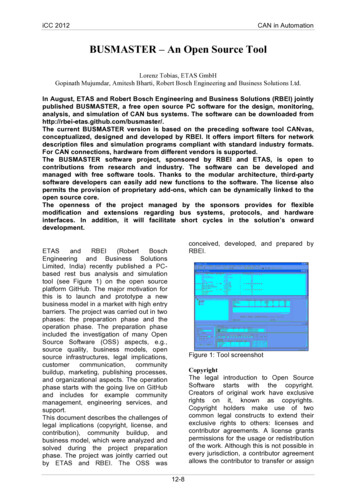
OLIMEX 2012OLinuXino-MICRO user's manualfuses of the processor:SD MBR BOOT(3) - BlownSD POWER GATE GPIO(21:20) – 10-PWM3For burning the fuse position we use the BitBurner software. This operation is discussed in detailsbefore. Proceed with great caution when burning fuses since it is irreversible operation.The first batches of the board and the SD-card used the Debian Linux image. After that we switchedover to ArchLinux for the ease of the package manager. Instructions how to build the ArchLinuxcan be found at the gitHub address of OLinuXino.2.6 Using BitBurnerIMPORTANT! MODIFYING THE FUSES IS IRREVERSIBLE PROCESS! BURNING THEWRONG FUSES MIGHT DAMAGE OLINUXINO IRREVERSIBLY! BURNING WRONGFUSES MIGHT CAUSE BOOT PROBLEMS!BURN FUSES AT OWN RISK!The bit burning is done via the USB of the computer connected to the OLINUXINO board and theBitBurner software. To be able to burn the fuses you will need to connect a USB-A to USB-A cablebetween a computer and the board's USB-HOST connector.Download BitBurner from NO/BitBurner.v1.0.4.6.zip. Extract it and start the .exe. If you connect everything youshould see and choose HID-compilant device from the “Select device” drop-down menu.Page 10 of 47
OLIMEX 2012OLinuXino-MICRO user's manual2.7 Building the Debian Linux imageNote that building the Linux image from scratch is a time-consuming task. Even with powerfulmachine and fast internet connection it might take few hours compiling. Some Linux distributionsmight lack the tools required to compile/build/execute scripts/download from repository – how toget those is not discussed below.The Linux image is created and downloaded from form. For the test here we used Debian 6.0 with GNOME visual libraries. The steps we did:1) From the terminal created folder “bin” in home folder:user@dist : mkdir binuser@dist : cd binAdd bin directory to PATH in order to do the next steps easier. Else navigate to the right folders.2) Installed repo utility needed for the bitbake file fetching from the repository:user@dist : curl /repo /bin/repouser@dist : chmod a x /bin/repo3) Created directory for the project and download the BSP source from the git repository:Page 11 of 47
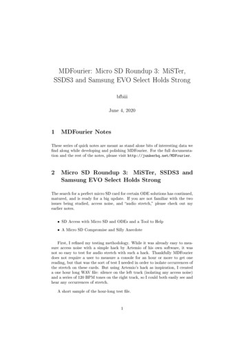
OLIMEX 2012OLinuXino-MICRO user's manualuser@dist : mkdir fsl-community-bspuser@dist : cd fsl-community-bsp /fsl-community-bsp : repo init -u tform -bdenzil /fsl-community-bsp : repo sync4) You can change the settings for the build if you want at fsl-community-bsp/build/conf/local.conf.I changed the “machine” name to “imx233-olinuxino-maxi”.For Linux kernel configurations and settings you can do (of course you can use also the defaultsettings): /fsl-community-bsp :. ./setup-environment build /fsl-community-bsp/build :bitbake linux-imx -c menuconfigCheck the image below:5) Now to start building the image: fsl-community-bsp :. ./setup-environment build fsl-community-bsp/build : bitbake core-image-minimalNote: on different Linux distributions you might have different tools installed and you will probablyneed to install dependencies needed for the compile/build scripts. Here are some (but not all) of themandatory ones: G ; diffstat; texi2html; chrpath; gawk; texinfo; some git client.To ensure you have the latest version supported with all the updates visithttps://github.com/OLIMEX/OLINUXINO and form.Page 12 of 47
OLIMEX 2012OLinuXino-MICRO user's manual2.8 How to blink the LEDIn this sub-chapter you will find a way to achieve the most basic task in electronics – the “HelloWorld” of electronics - blinking the LED.First we set the pin responsible for the LED as an output and we can set its value manually to highor low position – make it blink manually. The LED mounted on the board uses GPIO65. You canuse external diode instead of the one mounted - you have to look at the table “The Linuximplementation of pins” in the hardware section to get the correct linux name for the GPIO pin.echo out /sys/class/gpio/gpio65/directionecho 1 /sys/class/gpio/gpio65/valueIf you want to set the blink off you should change the value on the second line to:echo 0 /sys/class/gpio/gpio65/valueTo show the info for all GPIOs:ls /sys/class/gpioTo make it turn on – turn off automatically (e.g. blink) we use the text redactor VI to write theLinux script:echo out /sys/class/gpio/gpio65/directionwhile truedoecho 1 /sys/class/gpio/gpio65/valuesleep 1echo 0 /sys/class/gpio/gpio65/valuesleep 1doneWe save it as as “gpio” and we make it executable withchmod x gpiothen we execut the script with:./gpioThe LED should start blinking with 0.5Hz.2.9 How to setup Arch Linux distributionYou can refer to the manual of OLinuXino-MAXI for general build instructions but mind wehaven't tested the algorithm listed there on the MICRO. There shouldn't be significant differences. Ifyou meet such head over to the OLIMEX forums.Page 13 of 47
OLIMEX 2012OLinuXino-MICRO user's manual2.10 How setup the I2C, SPI, UARTThere are number of examples with our extension module board to achieve those connections on theUEXT. The examples might be used as an example for I2C, SPI or UART communication. You canfind them at our GitHub er/SOFTWARE/iMX233Page 14 of 47
OLIMEX 2012OLinuXino-MICRO user's manualCHAPTER 3: OLINUXINO BOARD DESCRIPTION3. Introduction to the chapterHere you get acquainted with the main parts of the board. Note the names used on the board mightdiffer from the names used below to describe them. For the actual names check the OLinuXinoboard itself.The top and the bottom view can be viewed on the next two pages of the manual. There isexplanation of the different peripherals in the following chapters of the manual.Page 15 of 47
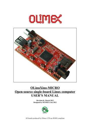
OLIMEX 2012OLinuXino-MICRO user's manual3.1 Layout (top view)Page 16 of 47
OLIMEX 2012OLinuXino-MICRO user's manual3.2 Layout (bottom view)Page 17 of 47
OLIMEX 2012OLinuXino-MICRO user's manualCHAPTER 4: THE iMX233 MICROCONTROLLER4. Introduction to the chapterIn this chapter is located the information about the heart of OLinuXino – its microcontroller. Theinformation is a modified version of the datasheet provided by its manufacturers.4.1 The microcontroller ARM926 CPU Running at 454 MHz Integrated ARM926EJ-S CP 16-Kbyte data cache and 16-Kbyte instruction cache— One-wire JTAG interface— Resistor-less boot mode selection using integrated OTP values 32Kbytes of Integrated Low-Power On-Chip RAM 64 Kbytes of Integrated Mask-Programmable On-Chip ROM 1 Kbit of On-Chip One-Time-Programmable (OCOTP) ROM Universal Serial Bus (USB) High-Speed (Up to 480 Mb/s), Full-Speed (Up to 12 Mb/s)— Full-speed/high-speed USB device and host functions— Fully integrated full-speed/high-speed Physical Layer Protocol (PHY)— Mass storage host-capable (uncertified by USB-IF) Power Management Unit— Single inductor DC-DC switched converter with multi-channel output supporting Li-Ionbatteries.— Features multi-channel outputs for VDDIO (3.3 V), VDDD (1.2 V), VDDA (1.8 V),VDDM (2.5V) and regulated 4.2V source.— Direct power from 5-V source (USB, wall power, or other source), with programmablecurrent limits for load and battery charge circuits.— Silicon speed and temperature sensors enable adaptive power management overtemperature and silicon process. Audio Codec— Stereo headphone DAC with 99 dB SNR— Stereo ADC with 85 dB SNR— Stereo headphone amplifier with short-circuit protection and direct drive to eliminatebulky capacitors— Amplifiers are designed for click/pop free operation.— Two stereo line inputs— Microphone input— SPDIF digital out 16-Channel Low-Resolution ADC— 6 independent channels and 10 dedicated channels— Resistive touchscreen controller— Temperature sensor controllerPage 18 of 47
OLIMEX 2012OLinuXino-MICRO user's manual— Absolute accuracy of 1.3% Security Features— Read-only unique ID for digital rights management algorithms— Secure boot using 128-bit AES hardware decryption— SHA-1 hashing hardware— Customer-programmed (OTP) 128 bit AES key is never visible to software. External Memory Interface (EMI)— Provides memory-mapped (load/store) access to external memories— Supports the following types DRAM:— 1.8V Mobile DDR— Standard 2.5V DDR1 Wide Assortment of External Media Interfaces— High-speed MMC, secure digital (SD)— Hardware Reed-Solomon Error Correction Code (ECC) engine offers industry-leadingprotection and performance for NANDs.— Hardware BCH ECC engine allowing for up to 20-bit correction and programmableredundant area. Dual Peripheral Bus Bridges with 18 DMA Channels— Multiple peripheral clock domains save power while optimizing performance.— Direct Memory Access (DMA) with sophisticated linked DMA command architecturesaves power and off-loads the CPU. Highly Flexible Display Controller— 8-bit data ITU-R BT.656 D1 digital video stream output mode (PAL/NTSC), with onthefly RGB to YCbCr color-space-conversion.— Flexible input formats Pixel Processing Pipeline (PXP)— Provides full path from color-space conversion, scaling, alpha-blending to rotationwithout intermediate memory access— Bi-linear scaling algorithm with cropping and letterboxing— Alpha-blend, BITBLT, color-keying— Memory efficient block-based rotation engine Integrated TV-Out Support— Integrated PAL/NTSC TV-encoder fully pipelined to display controller’s D1 resolutionoutput stream— Integrated low-power 10-bit Video DAC (VDAC) for composite analog video output. Data Co-Processor (DCP)— AES 128-bit encryption/decryption— SHA-1 hashing— High-speed memory copy Three Universal Asynchronous Receiver-Transmitters (UARTs)— Two high-speed application UARTs operating up to 3.25 Mb/s with hardware flowcontrol and dual DMA.— Debug UART operates at up to 115Kb/s using programmed I/O. I2C Master/Slave— DMA control of an entire EEPROM or other device read/write transaction without CPUPage 19 of 47
OLIMEX 2012OLinuXino-MICRO user's manualintervention Dual Synchronous Serial Ports (for SPI, MMC, SDIO, Triflash)— 1-bit, 4-bit and 8-bit MMC/SD/SDIO modes— Compliant with SDIO Rev. 2.0— SPI with single, dual and quad modes. Four-Channel 16-Bit Timer with Rotary Decoder Five-Channel Pulse Width Modulator (PWM) Real-Time Clock— Alarm clock can turn the system on.— Uses the existing 24-MHz XTAL for low cost or optional low power crystal (32.768 kHzor 32.0 kHz), customer-selectable via OTP. Customer-Programmable One-Time-Programmable (OTP) ROM via Integrated eFuse Block— Resistor-less boot mode selection— 128-bit boot mode crypto key— Boot mode specification of NAND characteristics for device that the customer issoldering to the board. This means no more costly
OLIMEX 2012 OLinuXino-MICRO user's manual Customers have full access to the technical documentation of the board. The software is released under General Purpose License and the board is considered open-hardware. 1.3 Organization Each section in this document covers a separate topic, organized as follow: