Transcription
r Mining ApplicationsTraditionally, there has been a rather ad hoc attitude towards technical supervision of mining engineering groundcontrol programs, to the extent that the preparation andenforcement of specifications has not been a major issue.In certain locations, however, the dominant use of contracting companies to provide mining-related services hasmeant that structured specifications are needed to ensurethe high quality of the end-product. This is perhaps particularly the case with shotcrete (1) now that more andmore mines are using the process and product to enhancethe ground control regime within the mine.by David F. Woode principal objective of this paper is to develop a rigorous method of estimating the volume of shotcrete needed for any particularmining project. The paper starts with an assessmentofthe rock mass and excavation conditions, and continues with an evaluation of the shotcrete placementprocess as it relates to wastage of shotcrete throughrebound. Design charts are presented to assist in thechallenging task of estimating shotcrete volumesbased on different concepts of "thickness."Finally, when considering terminology, a cleardistinction is required between: Placement-which is the act of sprayingshot/concrete, andT Application-which deals with the suitability ofusing shotcrete under different rock engineeringconditions.Effect of Shape of Mined ExcavationOnce the design engineer has planned the excavation dimensions and shape, the theoretical excavation perimeter can be determined. An estimate ofthe volume of shotcrete required per linear metre ofdrift can be made for a given thickness of shotcreteand a predetermined allowance for rebound . Thereare two issues , however, which have an impact onthe final excavated perimeter. They are the irregularities of the excavated surface caused by the condition of the rock mass (such characteristics cannotbe engineered) and the irregularities of the excavated surface caused by the excavation process itself (which can be engineered).12The first issue is referred to as the Ground Condition Irregularity and is primarily a function of therock mass quality. The second is referred to as theDrill and Blast Process and is wholly a function ofthe mining or development contractor's ability toaccurately and consistently carry out high qualitycontrolled blasting. These two components comprisethe Roughness Factor.Ground Condition IrregularityThe irregularity of the rock mass surface after excavation as a function of the natural condition ofthe ground is a function of the following parameters: The blockiness of ground, predominantly due toblock size and block shape The tightness of ground, predominantly due tothe aperture of discontinuity surfaces The orientations of natural structures, especiallyrelative to the orientation of the mining excavationsThe presence of faults and their interaction withthe excavation profileThe presence of groundwater The presence of cl ay seams The degree of foliation in metamorphic rocks ,and The presence of minerals on slip planesFour discreet combinations are proposed whichreflect decreasing rock mass quality:Excellent Condition-No geological effect. Therock mass does not influence the final perimeter ofthe excavation.Good Surface Condition-Some jointing withslightlyrough surfaces. The rock mass has a low influence on the perimeter of the excavation.Fair Surface Condition-Blocky grou nd andsmooth surfaces. The rock mass has a significantinfluence on the perimeter of the excavation.Poor Surface Condition-Very blocky ground,polished surfaces, possible fau lt zones and wetground. The rock mass has a significant influenceon the perimeter of the excavation .The effect of the inherent character of the rockmass is that a certain amount of overbreak outsidedesign is inevitable and the surface area of the rockShotcrete Magazine August 1999
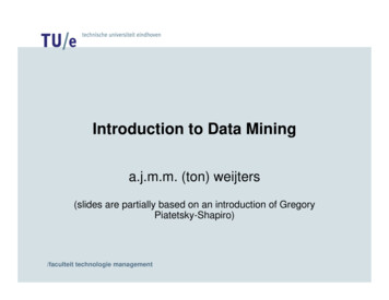
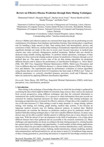
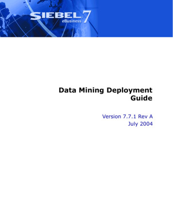
mass fo r a certain drivelength is increased. Foreac h ground condi tionirregularity, the length ofthe perimeter of the surface is increased by thefac tors shown on Figure l.Drill and BlastProcessThe control of the excavati on process may beconsidered a function of: The design of blasting pattern , particularly the location andc hargin g des ign ofthe bl ast holesGROUND CONDITIONDRILL & BLAST PROCESSExcellent CondtionDesigned Surface AreaFactor 1.0Perfect ConditionsHalf Barrels ThroughoutFactor 1.05Good Surface ConS lightly Rough SurfaceFactor 1.2Good Drill & BlastProcessHalf Barrels Across BackFactor 1.1Fair Surface ConditionBroken SurfaceFactor 1.4Poor Surface ConditionVery Blocky GroundFactor 1.6Fair Excavation ControlModerate Ove rbreakFactor 1 .15Poor Mining PracticesConsiderable OverbreakFactor 1 .25 T he layo ut of th e Figure 1. Ground Condition Irregularity and Drill and Blast Process.bl as t des ig n, es pecially the accuracy of surveying or estimating the cess is considered to be lower than that of the groundcondition. It is also noted that the two processes actlocations of the bl ast holesindependently of each other and should be consid The drilling orientation, especiall y of the con- ered separately.trolled bl asting perimeter holes across the backand down the sidewall sThe Roughness FactorThe Roughness Factor is found by mul tiplying The charging accuracy. This refers to the accuthe two factors found from an evaluation of the naturacy with which the explosives are located withinral rock mass conditions and the excavation prothe bl ast holes and the types of explosives usedcess, as shown on Tabl e I .in various holesThe prime di agonal has been hi ghl ighted as a The injti ation sequence. If the holes are loaded likely combination of the two fac tors. The Roughproperl y but the millisecond delay times and the ness Factors fro m the prime diagonal are used ininitiation sequence are fl awed, then the rock mass Table 2.will suffer more than the minimum amount ofReboundoverbreak.Up to thi s point, no consideration has been madeFour di screet combinations are proposed whi ch for the influence of the installation of any groundrefl ect decreasing excavation process quality:support system. However, the placement of shotcretePerfect- Half barrels visibl e thro ughout. Onl y a will inev itably lead to some rebound and overspraysmall amount of additional excavati on perimeter is that will increase the volume of shotcrete that needsgenerated fro m the inevitabl e "lookout" of the drill to be ordered to achieve the desired resul ts. Thi sholes.section will also introduce different co ncepts ofGood-75 % half barrels visibl e across back. "thickness."Some deficiencies in the excavation process lead toShotcrete rebound is primarily a function of theadditi onal overbreak beyond design.particle size distribution of the coarse and fi ne agFair- Moderate overbreak outside design.gregates, and the velocity of impact of the shotcretePoor-Considerabl e overbreak outside design. materi als.Profound difficulti es in the excavation process leadto considerable overbreak.Roughness Factor:(NOT including Rebound or other fac tors)The effect of the excavation process on the rockGround ConditionDrill and Blast Processmass is that a certain additi onal amount of overbreakPerfectGoodFairPooroutside design is caused and the surface area of the1.101.151.251.05Factorrock mass for a certain drive length is increased.Excellent1.001.051.101.151.25For each drill and bl ast combination, the length of1.261.38Good1.201.321.50the perimeter of the surface is increased by the facFair1.401.471.541.611.75tors shown on Figure 2. It is noted that these facto rsare smaller than those for the ground condition irPoor1.601.681.761.842.00regul arity since the influence of the excavation pro- Table 1. Roughness FactorShotcrete Magazine August 199913
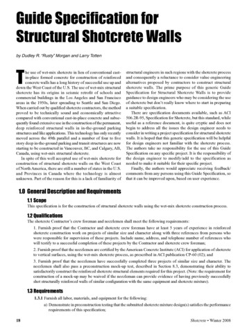
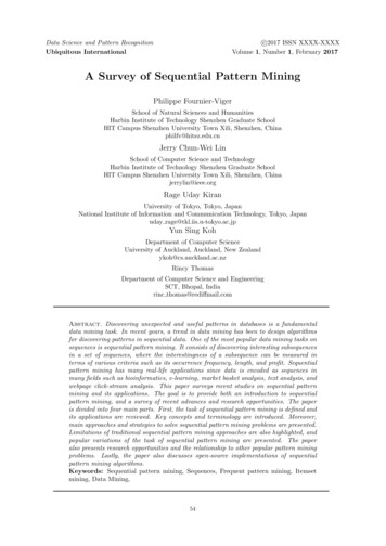
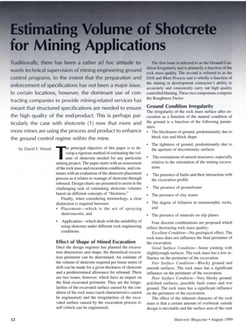
Cumulative Rebound30%"Cc:::l20%0.cQ)a: 10%0%mm 0in0502100415062008Average ThicknessFigure 3. Cumulative Rebound with Thickness Placed Particle size distribution depends on the Aggregate blend, Sand, Cement, and Silica fume Velocity of impact depends on the Pressure in the line or air flow, Distance of the nozzle from thereceiving surface, and Orientation of the nozzleA dense, well-placed shotcrete layerwill usually exhibit a good distribution ofaggregate particles including coarse aggregate to a maximum of about 10 mm (3fs in.).The most common aggregate blend seenin international projects is close to theAmerican Concrete Institute's GradationNo. 2 as shown in ACI 506R-90.A well-designed shotcrete mix will alsohelp to reduce rebound. There must be sufficient fine materials (cement and silicafume) to adequately cover the total surfacearea of the sand and aggregate particles.Since there is a high proportion of sandand relatively small aggregate in comparison with conventional cast concrete, the cement contents of shotcretes tend to be high.This is another reason that shotcretestrengths are high. If the cement content istoo low, rebound will again increase sincethere will be too little sticky paste for embedment and dynamic compaction.The relationships between rebound andvelocity of impact are equipment dependent and so specific rebound values are notpresented. In general, however, there willbe an optimum air pressure or volume flowrate, an optimum distance between thenozzle and the receiving surface and theshotcrete stream should be maintained perpendicular to the receiving surface.It is also noted that rebound is a function of the total placed thickness ofshotcrete Rebound is high at the beginning of ashoot, and Rebound becomes lower with increasing thickness.This concept is true for all shotcrete butis far more prevalent when using the drymix process. As the first material strikesthe receiving surface a very high proportion of the coarse aggregate and steel fibers bounces off the surface. Coarser rna-Figure 4. Thickness of ShotcreteMinimum 25 mm (I in.) Average 50 mm (2 in.), 15% Rebound14Irregular rockmass surfaceterial cannot embed itself into the plasticshotcrete until a paste layer has been builtup on the surface. This initial layer is usually rich in cement and is commonly responsible for the good bond developed byshotcrete. Once the coarser material canbecome part of the increasing layer, dynamic compaction starts to take place thatleads to the development of high strengths.As the layer thickness increases further, theinstantaneous rebound drops to almost zeroin the case of wet-mix process shotcrete.The cumulative rebound figures for wetmix shotcrete (the total amount of reboundfor a particular section thickness) areshown in Figure 3.This curve demonstrates the relationship between total anticipated rebound forwell-placed shotcrete and the section thickness called for. Site specific versions ofthischart could be produced by physically measuring the rebound values during pre-construction testing. The curve is based onfield observations and various publishedvalues for rebound.ThicknessThe definition of thickness in mining engineering applications is not at all straightforward . For a smooth walled excavationsuch as a tunnel boring machine (TBM)driven civil engineering tunnel, the concept of a uniform layer of a specified thickness is reasonable. This would be considered to be a "coating" by Windsor andThompson (I 999) (2). The "coat and fill"suggested by Windsor and Thompson ismore likely for mining applications inwhich a minimum coating thickness is required, but in order to successfully achievethis absolute minimum some additionalfilling of hollows in the rock mass isneeded. The "fill " profile, in which all ofthe hollows are filled and the surface between is relatively smooth is unlikely inmining due to high volumes of material required.Thus, in a mining application of shotcrete in a drill andblast excavation, there is nosingle concept of "thickness"that applies. If the design engineer calls for an absoluteminimum thickness of 25 mm(1 in.), then he will likely needan average of 50 mm (2 in.) toprovide the desired cover. Figure 3 shows that this averagelayer thickness would probablyShotcrete Magazine August 1999
be associated with a minimum of 15 % rebound .If the des ign is for a minimum of 50 mm(2 in.), then it is likely that an average of75 mm (3 in .) will be needed and the associated rebound fig ure could dro p to 10%.If the des ign call s fo r a minimum of 75mm (3 in .), an average of 100 mm (4 in.)mi ght appl y and the rebound could dropfurther to 7.5%. The majority of miningapplicati ons of shotcrete call fo r thi cknesses of 50, 75 or 100 mm (2, 3, or 4 in .).It is quite common to see the thickness desc rib ed as a " minimum thi ck ness ,"although estimating volumes based onminimum thickness is not recommended.It is strongly suggested that the notion ofminimum coating plu s some fi lling is themethod used to specify shotcrete in drilland bl ast applications.Figure 4 shows the placement of a minimum coating of 25 mm (1 in.) with localfi lling to 75 mm (3 in.). Thi s illustrates howdiffic ult it would be to assume that a uni fo rm layer thickness could ever be successfull y specified in a mining project.Volume .00Table 2. Vo lume Factorli ke ly th at a rock mass givin g a poorRoughness Factor would onl y require 50or 75 mm (2 or 3 in.) of shotcrete. Similarl y, a high quality rock mass that is wellexcavated would be unlikely to warrant a75 or 100 mm (3 or 4 in.) shotcrete layer.The numbers fo und for des ign purposesfro m this table are similar to those that havebeen developed empi ricall y over the lastfew years by the mi ning industry in Australi a. The process shown in thi s paper allows the engineer to determine where thedifferent components of the overall VolumeFactor come fro m.Planning ProcessSteps in the Planning ProcessIt has been shown that the surface of anexcavation driven by drill and bl ast methods is far from smooth and unifo rm, andthe perimeter of the excavation boundaryis much larger than designed. The amountof overbreak is a function of the inherentcharacter of the ground-rock mass quality-and the actual excavati on processqu a lity co ntro l of the drill a nd bl astmethod. The impact of the pl acement ofshotcrete can also be taken into considerati on at the des ign phase by consideringthe required thickness, as both a minimumand an average. Different levels of reboundcan be attributed to different total secti onthickness, so it is now possible to estimatea Volume Factor for a specific applicationusing site specific values fo r Ground Condition, Drill and Blast Process and Rebound, using Table 2.The Roughness Factors shown in Table2 are taken from the prime diagonal fromTable 1. It is noted that any combinationof Ground Condition and Drill and BlastProcess ca n be used to dete rmin e th eRo ug hn ess Factor, a nd the Re bo undFactor can then be used to generate a specific Volume Factor.The grayed-out zones on Table 2 referto matrix intersections that are not likelyto exist in reality. For example, it is un-The fo llowing outline presents the pl annin g process requi re d fo r es tim atin gshotcrete volumes in a drill and blast mining operation. Select locati on need ing shotcreteShotcrete Magazine August 1999 Estimate volume fac tor and calcul atevolume req uired Instruct contractor accordingly. A typical shotcrete request form should include precise info rmation concerningth e tim e a nd the locati o n of th eshotcreting, and a sketch on a cross section or pl an view of the profile, including overbreak and fall outs . Above all ,such a req uest form must include info rmation on the length, the perimeter, thethickness, the fac tor , and the volumeshotcreted, both as es timated and asshot. It then represents a hardcopy ofthe differe nces, if any, between the es-Continued next page Decide on plain or mesh reinforcedshotcrete or fiber-rei nforced shotcrete(Fibercrete) Determine area to be shot Confirm des ign shape per engineering Determine excavated shape by sitereview Estimate geological facto rs Estimate drill and blast factors Measure effective round/cut length(this may be more than the excavatedcut length depending on loss ofpreviously appli ed shotcrete, forexample) Estimate design area needingshotcrete Estimate ro ughness factor Consider design thickness (minimumand average) Estimate rebound fac tor15
Continued from previous pagetimated and the real quantity applied forevery section of the opening shotcreted.There are a number of other considerations that may come into play when designing a shotcrete program (quality ofscaling walls and back, operator training,fall outs, presence of other support systems,etc.). They may all have an influence onthe amount of shotcrete placed, and mayor may not be under the control of theplacement contractor.ConclusionsOne of the most demanding parts of ashotcrete program in the mining industryis determining what sort of contract to enter into with the placement contractor. Oneprocess commonly encountered in miningis for the design engineer to estimate therequired volume of shotcrete based on thedesign profile of the excavation with asmall allowance for rebound and wastage.Having made this estimate and instructedthe contractor to place a certain volume ofmaterial on the rock mass around the excavation, the engineer is surprised to findthat the volume requested did not cover theground to the desired thickness. Almostinevitably, a conflict starts to develop between the two parties since the engineerand the contractor are looking at the problem from two different viewpoints.It is hoped that by using a process suchas that suggested in this paper, less conflict will arise by making both parties moreaware of the considerations that need to bemade during the design phase of theproject. A clear understanding of the concept of thickness needs to be made beforea decision is taken on how to word the"Payment" clause of the contract. If thecontractor is to assume the majority of therisk, then unit costs will be high . If theowner and the contractor find a way toshare the risk and agree to pay on "cubicmetres through the pot," then both partiesmust use a shotcrete request form, andreach a consensus about the required volume of shotcrete materials to be placed.AcknowledgementsThis paper is based on a presentation madeat the Engineering Foundation's Shotcretefor Underground Support VIII held inCampos do Jordao, Brazil in Ap1il 1999. Iappreciate the opportunity to be offered aforum to explore ideas such as these in anopen framework. I would also like to thankMarnie Pascoe, now with Australian Mining Consultants, for her pioneering workin trying to unravel the difficulties in estimating shotcrete volumes in miningprojects. References1. Throughout this article, the term"shotcrete" is used to include the process of pneumatically placing concreteand the product thus created. It includes"sprayed concrete" and does not inferthe wet-mix or the dry-mix process. Itusually implies a blended aggregatewith up to 7-9 mm C/2- 1/3 in.) sized particles, although it may also be synonymous with the old term "gunite" (a termrestricted to the use of dry-mix processand sand sized aggregate).2. C.R. Windsor and A.G. Thompson, Thedesign of shotcrete linings for excavations created by drill and blast methodsin Rock Support and ReinforcementPractice in Mining, Eds. E. Villaescusa,C.R. Windsor and A.G. Thompson.Balkema, pp 231-242, 1999.David Wood is a registered Professionaland Chartered Engineer practicing in RockEngineering and Engineering Geologywith 25 years experience in consultinggeotechnical engineering programs inNorth and South America, Europe, Australia, Africa and Asia. His experience comprises rock mass evaluation, rock hazardappraisal, rock engineering analysis anddesign, rock slope stability assessment andstabilization design, engineering geological and geotechnical field data-collectionstudies, and report preparation for smalland large-scale civil and mining projects.16Shotcrete Magazine August 1999
ship between total anticipated rebound for well-placed shotcrete and the section thick ness called for. Site specific versions ofthis chart could be produced by physically mea suring the rebound values during pre-con struction testing. The curve is based on field observations and various published values for rebound. Thickness