Transcription
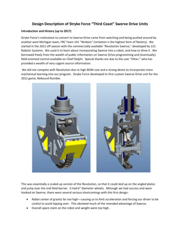
Design Description of Stryke Force “Third Coast” Swerve Drive UnitsIntroduction and History (up to 2017)Stryke Force’s motivation to convert to Swerve Drive came from watching and being pushed around byanother west Michigan team, FRC Team 141 “Wobots” (imitation is the highest form of flattery). Westarted in the 2011 off season with the commercially available “Revolution Swerve,” developed by 221Robotic Systems. We used it to learn about incorporating Swerve into a robot, and how to drive it. Weborrowed freely from the wealth of public information on Swerve Drive programming and (eventually)field-oriented control available on Chief Delphi. Special thanks are due to the user “Ether,” who hasprovided a wealth of very cogent source information.We did not compete with Revolution due to high BOM cost and a strong desire to incorporate moremechanical learning into our program. Stryke Force developed its first custom Swerve Drive unit for the2012 game, Rebound Rumble.This was essentially a scaled-up version of the Revolution, so that it could skid up on the angled platesand jump over the mid field barrier. It had 6” diameter wheels. Although we had success and werehooked on Swerve, there were several serious shortcomings with this first design: Robot center of gravity far too high—causing us to limit acceleration and forcing our driver to becareful to avoid tipping over. This obviated much of the intended advantage of Swerve.Overall space claim on the robot and weight were too high.
Too much weight on the perimeter of the robot—limiting rotationalacceleration/maneuverability.Difficulty driving straight in autonomous and dealing with obstacles.Our design for Ultimate Ascent in 2013 attempted to address some of these shortfalls by limiting wheelsize to 4”, removing discrete bushings for the rotation (employing the housings themselves), addingposi-traction, and adding a servo-actuated, dog clutch two-speed transmission. For the first time, wealso 3D printed timing belt pulleys to facilitate the design of the two-speed transmission.This swerve design was a large improvement. The ¼” throw posi-traction was helpful in improving thecontrol of the robot, but also made it sway during hard maneuvering and the recoil of the Frisbeeshooter was visible in the mechanism. There were some other, more significant, shortfalls: COG still too highSpace claim and weight still higher than desired.Shifting time limited utility of transmission.High maintenanceo Custom wheels/treado Multiple chains, which are pinch hazards and need to be adjusted periodically.o Multiple belts, which were prone to failureo Insufficient thickness in mounting plate on robot, leading to bendingo Motor mounting issues leading to belt walk.
Our next iteration, developed for 2014’s Aerial Assist game, began an emphasis on simplification. Themost significant and visible change was the elimination of the horizontal drive shaft and thecorresponding move to “dually” wheel sets. Overall height and complexity were reduced relative toprevious iterations, reliability was improved, and the maintenance load on the pit crew was dramaticallyreduced. We also started to notice improved handling. It was visibly unique, and our team started toidentify with it. Playing off the “West Coast Drive” name, we’ve taken to calling our dual wheel positraction swerve a “Third Coast Drive,” in reference to the Great Lakes region.Items targeted for improvement after competing with this first generation Third Coast Drive: WeightVertical drive shaft cantilevered off lower bearing too far—led to bent drive shafts.Conversion of azimuth chain to beltMethod of setting bevel gear mesh2015’s game, Recycle Rush, really didn’t emphasize the traditional capabilities of Swerve. However,since we had a lot of comfort and experience with it, we did it simply for the advantages ofmaneuverability in tight quarters. The main differences between this design and the former were thatwe changed how the axle was constructed and the bevel gear adjusted, and we converted the azimuthto belt drive. We also eliminated the bolted connection between the side plates and the top plate. Inthis version, this last change meant that we bolted a retainer for the axle bearings in from the bottom(not shown below).
In the off season between 2015 and 2016, we created a Third Coast Drive T-Shirt Cannon Robot. In thisdesign, we hoped to get rid of the hassles and time penalties of azimuth zeroing by shifting to absoluteencoders. We developed an in-house method of mounting an optical encoder on a Vex PlanetaryGearbox output—only to find out that Vex simultaneously released a similar product with a more robustmagnetic-based encoder!!! Other refinements included using a composite saddle, exploring using a gearset rather than pulleys and belts for azimuth control, moving to Colson wheels to improve wear,reduced wheel size to reduce the overall gear reduction needed, and elimination of secondarymachining on the wheels, and the axle bearing retainers. Overall, this module, which never saw FIRSTcompetition, was very light and a nice upgrade but we didn’t have faith in the composite saddles andazimuth gear set given the posi-traction axial motion.In our initial estimation, 2016’s game, FIRST Stronghold, did not lend itself to Swerve Drive. The amountof physical abuse we expected the robots to take gave us pause, and the wide variety of orientation inobstacles made us worry about Swerve’s appropriateness. Thus, we went to an eight wheel tank drivewith the outer wheels raised slightly for maneuverability. Each set of four wheels were mounted insuspended “skiis” intended to smooth out impacts going over obstacles. In hind sight, FRC 16 “BombSquad’s” robot for that game proved that Swerve could still be used to very good effect. Hat’s off totheir team’s insights on how to make that all work out.
With the wide-open field of 2017’s game, FIRST Steamworks, we went back to Swerve. This generationof Third Coast Drive started with what we learned from T-Shirt Cannon Robot and put a lot of emphasison simplicity, ease of manufacturing, and weight reduction. Key design elements were shifting to aNylon mounting “bonnet” vs. the traditional aluminum, and reduction of posi-traction throw to facilitatea stable shooting platform.2017 Stryke Force Third Coast Drive Detailed DescriptionWheel/Axle Assembly: Use of durable 2.5” Vex Colson wheels with ½” hex bores and Andy Mark’saffordable 2:1 bevel gear set allowed us to keep things simple and the drive pulley ratios reasonable. Touse the Andy Mark gears on axles made from Vex ½” Thunderhex, we removed the flange on the largegear’s back side, opened the 3/8” hex to ½” hex (drilling and broaching) and drilled a hole pattern in itsface matching the one in the Colson wheels. All torque is transmitted through the hex flats; the screwsare simply to keep the face of the gear flush against the wheel face, counteracting the moment createdby the bevel gear mesh forces.
The wheels are axially held in place on the axle with three snap rings (not shown); one for the gearedwheel (opposite side from the gear to take the mesh thrust), and one on each side of the non-gearedwheel. The location of the snap ring grooves in the axle is determined by the location to hold thegeared wheel in the nominal mesh location relative to the mating gear on the vertical drive shaft. Thenon-geared wheel is located symmetrically about the vertical drive shaft relative to the geared wheel.This is done so that scrubbing torques are equalized and the robot can stay stationary when azimuthinga Swerve unit. The axle length is set carefully so that it can just be rocked in position in the saddle whenthe bearings are not in place. This elimates the need for a complicated saddle with bearing retainerplates.Saddle: The incremental design goal for the saddle this year was for it to be machinable by build teamstudents using basic skills. The saddle starts life as a ¼” wall 4”x4” 6061-T6 Aluminum extrusion. Theextrusion is cut to length on a horizontal bandsaw and then cut in half using a vertical bandsaw. Thewidth is determined by what is necessary to provide complete support for the azimuth pulley diameterand the height is what is left after cleaning up the bandsaw cuts. The next step was to mill the saw-cutfaces in order to square them up. After the faces of the horseshoe are squared up, the axle shaft holesare carefully drilled and reamed to fit 1-1/8” OD Thunderhex flanged bearings. The top hole is thendrilled out to intersect the axle shaft axis at right angles. The bolt pattern at the top is also done on themill at this time and the holes are subsequently tapped. In order to minimize weight and sweptdiameter, the edges were chamfered and the bottom corners cut off around the axle bearings. Notethat in CAD, these corners are radiused, but on the actual robot, they were cut off at 45 degrees—simplyeasier for fabrication. On our prototypes we didn’t even bother with these cuts at all.Azimuth Pulleys: The azimuth pulleys were 3D printed by our sponsor in polycarbonate using acommercial FDM type printer (Fortus400MC). We have found that the teeth profiles need to betweaked a bit (opened 0.002”) to get the timing belt to settle into them fully.
Note that to be able to take advantage of the absolute encoder on the output of the azimuth gearbox,these two pulleys must be the same number of teeth. Also note that we now use HTD, 5mm pitch, 9mmwide belts. To minimize “backlash” due to belt stretch during direction reversals and possible slipping ofteeth, these belts need to be fairly tight. Earlier versions used XL type belts which weren’t quite assmooth or robust to the loads. The pulleys are a little wider than the belts in order to accommodate theposi-traction motion. One thing we struggled with in this design was durabiltiy of the hex drivenazimuth pulley. We prevented outright failure by JB Welding an SAE aluminum washer in around theboss surrounding the hex. This washer took the hoop stress and prevented the cracks we were seeing atthe hex vertices. The hex fit can still loosen a bit due to wear over the course of a tournament, leadingto some backlash in the system. We inspect for this closely and change them out as soon as we see onewith some relative motion. The hex shaft-mounted azimuth pulley is retained on its shaft with a washerand button head screw. Note that in order to keep the overall packaging as tight as possible, we cutdown the hex shafts to custom length and re-drill/tap the ends. Off the shelf shafts could be used if theazimuth actuator axis is moved further away from the Swerve Drive.Swerve Pivot Hub and Mounting Hub:These are the two “complicated” parts in the system which are currently done on a sponsor’s CNC lathewith secondary ops on a mill.
The Pivot Hub (left) is aluminum and supports an off the shelf 6” long Ø3/8” case hardened steel verticaldrive shaft (McMaster-Carr). This support is accomplished with a 7/8” OD flanged bearing (AndyMark)at the bottom, and a 7/16”OD needle bearing at the top (McMaster-Carr), both of which are pressed in.The separation of the two bearings nicely supports the vertical drive shaft. One key to success is to getthe lower bearing close to the bevel gear. If this distance gets too long, the 3/8” diameter drive shaftcan bend under the combined loading of the bevel gear thrust and wheel side loading. The Pivot Hub isbolted into the top of the saddle using flat head screws. It sandwiches the printed azimuth pulley and aspacer such that those printed plastic parts are vey well supported. The heads of the flat head screwsare slightly recessed below the face they go into. This is because that face serves as a thrust bearing forthe underside of the Mounting Hub. The hole pattern was originally determined by our use of off theshelf sprockets for our azimuth. At this point, it is vestigial, and since it drives us to make the milled“scallops” to clear the heads, we’ll probably be changing it on the next iteration. The moment istransferred through the assembly to the robot frame by two separated cylindrical faces. The first is thescalloped face and the second is the area immediately below the snap ring groove. The two faces andthe thrust face are all carefully deburred and lubricated. The Mounting Hub interfaces with these facesas described next.The Mounting Hub (right) is cast nylon, which makes a nice bushing material and is still strong. Therobot frame sits on the flange with the bolt pattern. The holes making up the bolt pattern in the flangeare tapped and this is how the Swerve Drive attaches to the robot.Positraction Description:For a robot to efficiently drive straight, the following must be satisfied:1. All wheels have same surface velocity. Usually:a. Same diameter
b. Same rotational speedc. Same traction2. All wheels pointed in the same direction (aligned)Pos-itraction helps with item 1c. Three points define a plane. More points are odd men out—inengineering speak, the plane is “overconstrained.” In practical terms, when four rigid swerve units areput on the ground, manufacturing tolerance stackup or post manufacture movement (such as from adamaging collision, or drop) cause one of the points to come off the ground. The robot will then be lessstable than it would otherwise be, possibly rocking, or will at least have less traction on the higherwheel. Even aligned, if the traction isn’t similar between wheels, the robot will not drive straight. Thepositraction spring is sized to push the Swerve Pivot Hub and Mounting Hubs apart with a force roughly20% of the fully weighted robot. Thus, the robot normally rides with its “suspension” bottomed out on athrust bearing. However, when one wheel starts to become unweighted or even comes off the carpet,the spring will push back down and keep the wheel in contact with the ground. We know from practicalexamples that the posi-traction works and will make up for significant frame bending. It also helpscontrol when accellerating hard, driving onto a shallow ramp or over minor obstacles. Unfortunately,the amount of travel must be limited to fairly small amounts, or the robot is not a stable shootingplatform. We limited travel to to approximately 3/32” for the 2017 robot because of the recoil from theShooter. The Nylon is protected from the end of the steel spring by a washer.Unit Assembly:The unit, less the Mounting Hub, Washers, and Spring is assembled off the robot.Shimming of the bevel gear set can either be done now or after mounting on the robot. Once assembledinto the saddles, the horizontal component of the mesh is adjusted by jacking the axle back and forthseveral thousandths from the nominal location. This jacking is accomplished using the ¼-20 button head
screw threaded into the Thunderhex bore (tapped) on the non-geared wheel side. Mesh is adjustedvertically with shims between the back of the vertical shaft bevel gear and the support bearing innerrace, (not shown). Mesh is proper when the gears line up as shown (maximizing facewidthengagement), have minimal backlash, and move freely through full rotation. Once set, the opposing ¼20 button head screw is tightened to lock the shaft in position. Both axle jacking screws are doped withBlue Loctite to prevent loosening. This process may need to be checked again after operation underload. Once re-adjusted after “burn in” we have not had to revisit the mesh during a season.Final Assembly:The Mounting Hubs are bolted into the robot frame. The posi-traction spring is set on the Pivot Hubwith a washer on top and then pushed into the Mounting Hubs from the bottom. The spring iscompressed until the snap ring groove at the top of the Pivot Hub comes through the top of theMounting Hub. A second washer is placed on top of the Mounting Hub and a 7/8” snap ring is put inplace to hold the whole thing together. The top washer protects the nylon of the Mounting Hub fromthe steel snap ring as it rotates with the Pivot Hub. Posi-traction motion can be reduced by addingwashers. Posi-traction force can be adjusted by adding washers inside the Monting Hub and/or grindingdown the spring.
Other Notes: We open the bore of the vertical drive shaft bevel gear and weld it to the drive shaft. We havealso succesfully cross-drilled and pined them, and used keyed connections in the past.It is good practice to try to get the Drive Pulley down close to the needle bearing in order tominimize that cantilever and the resultant moment loads on the shaft. However, we have nothad an issue with the upper portion of the shaft bending with the gear ratios we’re using.Give careful thought to how motors and gearboxes are mounted. Belt loadings can besignificant and if the shafts are not parallel to the Swerve Drive unit axis, belts will walk and slipoff pulleys. Also, note that our azimuth pulleys are significantly larger than the belt widths inorder to provide for posi-traction travel.Make allowances in your design to adjust belt tension for both drive and azimuth belts. Wemount the motors/gearboxes/encoders in either sections of tube, or printed structures asshown above and then bolt those down to structure using slots. The yellow “drive rails” arewelded or bolted into the robot frame. Note that this design accommodated either 775Proswith Cimiles or CIMs. The rear unit shows both in this screen shot.We set our azimuth motor pointing down (belt under the C-Channel in the above screen shot)and our drive motor pointing up (belt over the C-Channel above). The components nest withinthe belt paths to minimize overall footprint.In addition to the azimuth pulleys discussed above, we 3D print our drive pulleys to save weight.We make our hubs out of ¾” aluminum hex to reduce the stress on the plastic. We turn downthe ends of the hex to ½” round, slit them and then clamp onto the shaft through the slit roundsection using heavy duty collars. When tightened down, they don’t slip.Closed loop tuning will likely be necessary to get the whole package working nicely. Without it,larger motors, and/or gear ratios may be required. Tuning is discussed briefly below, but adetailed description is another subject .Stryke Force teaches a course on the subject in the offseason. A lot of information we go over is provided in CTR’s Talon SRX user manual/materials.o We like to use a BaneBot RS550 for the azimuth motor since it has plenty of power andis very lightweight. At various times we have geared it from 64:1 to 100:1 using Vexplanetary gearboxes with ½” hex output shaft and encoder stage. The pulleys are 1:1,and we use 2.5” Colson wheels set apart approximately 2-5/8.” Under position control,
with the Talson SRX PID loop properly tuned, that range of ratios easily turns the thosewheels on carpet and does so very quickly. The tuning is hot enough that the azimuthcontrol loop is marginally stable with the wheels in the air, but good on carpet.o This year, we used a Vex 775Pro drive motor with a Cimile and Cimcoder. The drivepulley ratio is adjusted to balance acceleration and top speed based on wheel size, thegame and driver preference. This year the drive pulley ratio was approximately 2.4:1.Since the Cimile has a ratio of 29:12 ( 2.42:1) and the AndyMark bevel gear set is 2:1,the total ratio used was 11.6:1 (2.42x2.4x2). Larger wheels would need more gearratio for similar performance. Note that if you use 775Pros, the motors need to becurrent limited or you will burn them up. The current limit necessary for robustness willdepend on how you gear and drive your robot. We use several driver techniques tohelp manage the issue. We are under closed loop velocity control during Auton andopen loop voltage control during Teleop.o Although our prototype robots and competition robots are nominally very similar, theirPID control loops are individually tuned and we will often re-tune them again after adrive train is broken in.We have helped other teams successfully get started with Swerve Drives based on our ThirdCoast design. One of the stumbling blocks is availability of 3D printing. Team 2054, “TechVikes” has done a conversion to (modified?) off the shelf pulleys and that may be worthexploring if robust printing isn’t available to you.We use the NavX gyro/accellerometer board to provide field orientation signal.We use USB connected flight controllers for the driver. The sticks then function similarly toflying a drone, but without the need to keep track of which way the drone is pointed: The leftstick is pushed forward to go down the field, left/right to move cross-wise, and pulled back tocome back. The right stick spins the robot clockwise or counter clockwise. This scheme allowsdrivers to easily drive in a straight line and spin while doing so if they desire. Without fieldorientation controls, this can be done, but requires difficult mental gymnastics by the driver.Even with this aid, there is no substitute for lots of driving practice.Chief Delphi has a wealth of information archived on its site. We’d like to thank its site managerand contributors, in particular “Ether” for publicly sharing and clearly communicating the criticalanalysis and algorythms necessary for Swerve and Field Orientated Controls implementation. Anexcellent place to start is 028 Ourswerve code is very accuractly described by this document and we would recommend it as astarting point independent of what coding language you are using. We write our code freshfrom the CD sources every year—and learn a lot every time.Thank you to everyone who has helped us get where we are. In particular, this swerve drivejourney started with inspiration from Wobots which led us to 221’s Revolution Swerve Drive.We’re grateful that they were there for us.Final Comments:Stryke Force didn’t arrive at this Third Coast Drive design on its own or overnight. It was an evolutionaryprocess combining inspiration, input, feedback, analysis, and experimentation. We believe it’s prettydarn good, but we’re not done and probably never will be. This is how great things are made possible,and one of the biggest lessons we hope to convey to our students.j
encoders. We developed an in-house method of mounting an optical encoder on a Vex Planetary Gearbox output—only to find out that Vex simultaneously released a similar product with a more robust magnetic-based encoder!!! Other refinements included using a composite saddle, exploring using a gear