Transcription
EVERYTHING YOU NEED TO KNOWABOUT MEMBRANE SWITCHESREV. A
TABLE OF CONTENTSWhat is a Membrane Switch?3What Are The Parts of a Membrane Switch?4Important Membrane Switch Considerations5How to Install a Membrane Switch6Non-tactile Switch7-89Tactile Feedback10Copper Flex Circuitry11-12Backlighting TechniqueSilicone-Rubber Keypads13Environmental Considerations14Visual Considerations15Why Use JN White162
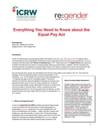
WHAT IS A MEMBRANE SWITCH?WHAT IS A MEMBRANE SWITCH?experience. Because of this flexibility, these man/machine interfaces are used across a wide range ofindustries, including medical, consumer electronics,military/DoD, and aerospace.A membrane switch is a momentary closure deviceused with a normally open circuit. They are calledmembrane switches because they are made up offlexible graphic and internal layers (or membranes)over a circuit printed on PET or etched onpolyimide.There are many parameters to consider inmembrane switch design including the graphics,overlays, adhesives, and use cases.The layered nature of membrane switchesallows a great deal of freedom for engineers todesign and implement a very precise customerNOT TO SCALE [RELATIVE ONLY IN PROPORTIONS]3
WHAT ARE THE PARTS OF A MEMBRANE SWITCH?SURFACE MOUNT DEVICES:There are many parameters to consider in thedevelopment of membrane switches, including thedesign, overlays, adhesives, and use cases. They canvary a great deal from simple to very complex. Thecomponents of a membrane switch will vary withcomplexity, but all contain some combination of thefollowing:Membrane switches can be designed withembedded LEDs if required.SHIELDING:GRAPHIC OVERLAYS:Proper shielding is necessary to meet ESD, EMI orRFI requirements.The overlay is the top layer of a membrane switchand is the interface between the user and themachine.TACTILE AND NON-TACTILE:Switches can be designed as tactile or non-tactile toachieve the desired product requirements.ADHESIVE:There are numerous differences in adhesives.Selecting the proper adhesive for a membraneswitch application requires consideration ofenvironmental, surface, appearance and otherperformance requirements.EMBOSSING:There are three basic styles of embossing; pillow,rim and dome. Depending on shape and size, logosand multi-level shapes can be embossed.CIRCUITS:Circuits can be printed conductive silver ink, etchedcopper flex or printed circuit boards.4
IMPORTANT MEMBRANE SWITCH CONSIDERATIONSWHY USE SILICON RUBBER KEYPADS?NON-TACTILE SWITCH WITH SILVERCIRCUITYMore complex user interfaces require higher-density,more miniatured components. In these situations,printed circuit boards (PCBs) and printed circuitboard assemblies (PCBAs) are often brought intoplay.This three-layer switch, comprised of graphicoverlay, a circuit spacer, and a screen-printed silverink circuit, is the simplest type of membrane switch.Because they tend to be the least expensive option,they are often implemented as a cost-cuttingmeasure in the overall design.WHAT IS TACTILE FEEDBACK?Tactile feedback refers to a mechanism in membraneswitches that utilizes touch for operation oractivation. By using different materials and sizesfor these domes, you can vary the actuation forcerequired to activate the switch.LED BACKLIGHTING OPTIONS FORMEMBRANE SWITCHDesigning the right backlighting technology intoa membrane switch assembly can help delivera superior user experience. A wide variety ofbacklighting options are available, allowingengineers to precisely manage light quality, color,intensity, and coverage, so it is important that yourselected switch manufacturer understands theadvantages and disadvantages of these differenttechniques.WHAT ARE COPPER FLEX MEMBRANESWITCHES?Unlike screen-printed silver, copper flex circuits aremanufactured by laminating copper to an underlyingsubstrate, and then etching that substrate in a waythat leaves specific conductive traces.DURABILITY IN HARSH ENVIRONMENTSVISUAL CONSIDERATIONS IN MEMBRANESWITCH DESIGNMore complex user interfaces require higher-density,more miniaturized components. In these situations,printed circuit boards (PCBs) and printed circuitboard assemblies (PCBAs) are often brought intoplay.Choose a vendor that has a computerized colorformulation system to achieve consistent resultsfrom printing to printing. Good suppliers can colormatch to the Pantone Matching System, FederalStandard Guide, a color swatch, or to your bezel.Calibrated light booths and/or digital densitometersare then used to inspect and measure results toensure conformance.5
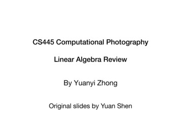
HOW TO INSTALL A MEMBRANE SWITCH1Very carefully cut and remove 1/8” of adhesiveliner on the bottom side of the membrane switch.2Turn the membrane switch over and pass theflex cable through the tail exit slot of the unit theswitch will be mounted to. With precision, positionthe membrane on the back support recess andadhere the membrane switch to the surface of theunit with the exposed adhesive.3Position the membrane with an angle around30 degrees, peel off the rest of the adhesiveliner keeping the set up the same as before. 4Gently laminate the membrane switch startingfrom the side with the removed adhesive liner,using a soft roller, apply slight pressure as rolledacross the top surface of the membrane switch. 5Lower the angle of the membrane switchgradually and roll out the air.6The lamination is completed. You can bendthe circuit slightly without damaging theswitches but use extreme caution so that themetal domes/buttons are not inverted thenbecoming non-functional.
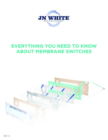
NON-TACTILE SWITCHThis three-layer switch, comprised of a graphic overlay, a circuit spacer, and a screen-printed silver ink circuit,is the simplest type of membrane switch. Because they tend to be the least expensive option, they are oftenimplemented as a cost-cutting measure in the overall design. However, because there is no tactile feel whenthese circuits are actuated, there is often a sound or light component put it place to indicate activation.Depending on the device and the design, electronic shielding techniques may also need to be incorporated.GRAPHIC OVERLAY:ADHESIVES:The overlay is the top layer of a membraneswitch and is the interface between you and themachine. The overlay creates the look and feelfor your product. Graphic overlays can be madeof polycarbonate, polyester or acrylic materials invarious gloss levels, textures, pencil hardness andgages to meet your needs.Selecting the proper adhesive for a membraneswitch application requires consideration ofenvironment, surface, appearance and otherperformance requirements.Surface contact is fundamental to adhesiveperformance. The strength of the bond isdetermined by the surface energy. High surfaceenergy materials (like an un-waxed car) are veryeasy to adhere to. For low surface energy materials(which are more like a highly waxed car), specialadhesives with flow agents are typically requiredto enhance both the initial bond and the long-termhold.Other factors to consider when selecting anadhesive technique include whether the surface istextured or smooth, flat or curved, and painted orunfinished.CIRCUIT SPACER:Non-tactile membrane switches can be designedwith a wide range of actuation forces. The actuationforce is determined by the circuit spacer thickness.The thicker the spacer, the more actuation forceis required. Conversely, the thinner the spacer, theless the actuation force. If required, a non-tactilemembrane switch can be designed as thin as .021”.7
NON-TACTILE SWITCH (continued)SILVER PET:SHIELDING:The circuity in this simplest of membrane switchestypically consists of conductive silver screenprinted onto an underlying flexible surface, such aspolyester. This approach is very simple, which makesit easier to design and produce, and therefore lessexpensive than copper flex or PCBA circuit layers.A good membrane switch manufacturer canrecommend and design the proper shielding tomeet your ESD, EMI, or RFI requirements.Most use two methods for shielding membraneswitches: 1) copper or aluminum foil with or withoutlaminated polyester to the second surface, or 2)screen printed conductive silver ink in a grid orcomplete coating on the first surface.When printed on .005 polyester, conductive silverink’s resistance range is 10 ohms to 100 ohms witha rating of 30 volts DC. These electrical propertiesare a key factor when determining whether screenprinted silver will be suitable for your specificproject since silver-printed circuits are for lowvoltage applications only.There are three common methods for groundingshields: 1) a tab can be attached to a stud orstandoff on the metal backer or the metal enclosure,2) the shield can be terminated into the pins ofthe membrane switch tail, or 3) the shield layer iswrapped around the membrane switch and groundto the enclosure.Different conductive and dielectric inks are availableto help engineers specify and manage theseelectrical properties more precisely.8
TACTILE FEEDBACKTactile membrane switches incorporate a metal dome or a polydome into the membrane assembly to achievea desired tactile response. By using different materials and sizes for these domes, you can vary the actuationforce required to activate the switch. An additional adhesive layer – called the dome retainer – is placed justunder the graphic overlay to hold the dome in place.GRAPHIC OVERLAY:typically reserved for copper flex or PCBA-baseddesigns.For tactile switches, the material selected isdetermined primarily by lifespan requirements.Another factor that can determine the platingchoice is the need to match the material of theunderlying circuit. For instance, gold on goldis a common approach to optimize electricalperformance.If you have an application that requires 50000actuations, polycarbonate is a good option;otherwise polyester is the material of choice. Lifecycle tests show that polyester can be actuatedover 1,000,000 times in a tactile switch withoutshowing signs of wear.For good tactile feedback in a membrane switch,choose an overlay thickness between .006 and.010. These thickness ranges will offer the durabilityto meet your requirements, with the sensitivity toprovide a quality tactile effect.POLYDOMES:METAL DOMES:Softer and quieter than metal domes, plasticpolydomes are another option for engineers tocreate a desired tactile experience.Metal domes come in a large variety of shapes andsizes, with actuation forces between 180 to 700grams. 340 grams is the most common.Metal domes are typically stainless steel, and arenickel-, silver-, or gold-plated. The selected platingdepends on the conductivity requirements of theswitch, chosen based on electrical resistance.Nickel is the standard, while gold drives down theresistance. Most screen-printed silver circuits arepaired with metal plated domes. Gold plating isTo make a polydome, a layer of polyester is screenprinted with silver “shorting” pad, and then it isthermo-formed into a dome. This also allows you tocreate multiple buttons across a single panel, and itis a very cost-effective technique for high-volumeswitches (after the cost of the initial tooling).9
COPPER FLEX CIRCUITRYUnlike screen-printed silver, copper flex circuits are manufactured by laminating copper to an underlyingsubstrate, and then etching that substrate in a way that leaves specific conductive traces. This is a morerigorous process than screen-printing, but it results in a more flexible, more durable, and more precise circuit.In addition, the base material of copper flex circuits is polyimide – a very high temperature substrate thatallows you to surface mount components such as LEDs, resistors, and light sensors.BASE MATERIAL:insurmountable interconnection challenges. Theresult is reduced weight, reduced size, and reducedoverall thickness.The typical base material for a copper flex circuit is.001″, .002″, 0.3″ and .005″ polyimide or polyester.Unlike silver flex (which uses a conductive epoxy),these materials will hold up to the robust solderrequired to attach components.EMBEDDED COMPONENTS:To enhance user feedback, membrane switchesare often designed with (but are not limited to)embedded LEDs, light sensors, and resistors. Thesesurface-mounted components can be adheredto the circuit layer with conductive epoxy andencapsulated with a UV cured polyurethane.COPPER FLEX:The copper can be either .50z, 1.00z, or 2.00z RA orED copper.However, if copper polyimide circuits are beingused, the components can be soldered into place,for a much more durable result. This becomes asignificant advantage in manufacturing, as you canautomate the application of solder and parts withpick and place methods.One of the key advantages of copper flex circuitry isthe precision it gives engineers when managing thesize and space (or pitch) between the conductivetraces. With silver, the minimum pitch is 1mm.Meanwhile, the minimum trace width for copperflex is .004″ with a pitch of .004″. This becomescritically important in compact devices whereswithc size must be as compressed as possible. Itis also important when a small connection must bemade on the mating PCBA, since surface area isalways at a premium on small “mother boards”.Another advantage of copper flex is its abilitywithstand bending and creasing. This allowsengineers to design extremely compact switchassemblies, leveraging flexible circuits and complex,intricate paths to solve what would otherwise be10
BACKLIGHTING TECHNIQUEDesigning the right backlighting technology into a membrane switch assembly can help deliver a superioruser experience. A wide variety of backlighting options are available, allowing engineers to preciselymanage light quality, color, intensity, and coverage, so it is important that your selected switch manufacturerunderstands the advantages and disadvantages of these different techniques.EL LAMPS:Solid-state electroluminescent (EL) lamps produce light by charging phosphors with AC/DC current. Theyare highly efficient and provide an extremely even appearance. In membrane switch assemblies, EL lampsare typically implemented as a panel just beneath the graphic overlay. They do require an alternating currentsource, so they are not appropriate for all applications. However, in devices that already feature inverters, ELlamps can be an ideal backlighting option.11
BACKLIGHTING TECHNIQUE (continued)FIBER OPTICS:By shining an LED through optical fibers, engineers can illuminate very specific parts of a membrane switch.This precision, combined with the low cost and low temperatures associated with fiber optics, make this apreferred technique for many applications. However, depending on the number of fibers that are broughttogether at an LED, there can be a bulky pigtail. To overcome this physical limitation, many designers willspecify woven, fiber optic pads. These can be expensive, but they result in a compact, low-power highlycontrolled backlighting result.LGL:With LGL – Light Guide Layer technology – a light-diffusing plastic material is used to evenly backlight broadareas with LED sources. LGL is more cost-effective than woven fiber optic pads. However, more LEDs arerequired to achieve the same backlighting effect, so while LGL can be a very good choice for high-volume,low-cost applications, this approach does require more components. Manufacturing automation can becomea critical deciding factor when implementing LGL technology.12
SILICONE-RUBBER KEYPADSMore complex user interfaces require higher-density, more miniaturized components. In these situations,printed circuit boards (PCBs) and printed circuit board assemblies (PCBAs) are often brought into play. Awide range of layers and thicknesses are available, allowing engineers to address a wide range of designrequirements. When combined with custom-molded, silicone-rubber keypads, the result is a unique andreliable user experience.PCBAS:SILICONE-RUBBER KEYPADS:Printed circuit board assemblies (PCBAs) can besingle or multiple layers (up to 16 layers typical).These keypads help to deliver unique tactilefeedback and a distinctive visual appearance. Theycan be custom-molded in different shapes, patterns,and colors to support user-friendly backlightingoptions.Using PCBAs in the membrane switch assemblyaffords many advantages to design engineers.Unlike a simple membrane switch featuring a tailthat plugs into a device’s motherboard (whichare always starved for real estate), PCBA-basedswitches provide another platform for electronics.Silicone-rubber keypads are ideal for industrialenvironments, where a bold look and a morerugged, robust interface is required. With thecorrect design features, they allow you tocompletely seal a product from moisture, dust, andother environmental conditions, and they can alsoprovide a level of vibration resistance.These secondary boards can be used to offloada portion of the circuitry to the switch, with thetop layers of the board reserved for the interfaceand the bottom layers reserved for the product.Conversely, the PCBA in the switch can house all ofthe necessary electronics, eliminating the need for amotherboard altogether.The typical base material for PCBAs is FR4, CEM-1or CEM-4. A wide range of thicknesses are available,ranging from .020” to .13”. Depending on thematerials and thicknesses selected, PCBAs can helpprovide back panel support, in addition to providinga base structure for components and circuitry.Minimum trace width for gold .003”, and for hotair leveling .006”. Plating thickness dependenton material can either be 1 micron to 25 microns.Plating options include copper, carbon, nickel orgold.13
ENVIRONMENTAL CONSIDERATIONSDURABILITY:WEATHER SEALING:Membrane switches need to be reliable for years,all the while being used on a daily or even hourlybasis. This requires active and purposeful design forlifetime actuation.Depending on the application, membrane switchescan be exposed to a range of adverse weatherconditions. In these situations, the ability to sealand protect internal components from moisturebecomes critical.The balance between visual and tactile qualitiesand the need for ongoing durability can be asignificant challenge, particularly when paired withever-present budgetary constraints. By workingwith experienced membrane switch designers andmanufacturers, engineers can leverage this supplychain expertise to optimize components to addressthis requirement.A variety of construction options are available (3MHV tapes, custom-designed solid gaskets, etc.) thatallow engineers to design interface assemblies thatmeet a range of different environmental standards.For instance, membrane switches can be developedto meet IP sealing standards, to handle submersiontesting applications, or to support NEMA closurerequirements.Polycarbonate is easier to work with, but it is not asdurable as polyester, so instead many manufacturersare opting for blended materials. Thesecombinations of polyester and polycarbonate canhelp engineers address visual and environmentalrequirements across a range of dimensions.MATERIALS SECTION:Because of their many applications, membraneswitches need to withstand a range ofenvironments. Dirt and grime, moisture, andchemical cleaners can all take their toll.By using polyester materials for the top layergraphic overlay, you can maximize environmentaldurability and chemical resistance. However,polyester’s dimensional stability also makes itdifficult to form, so visual embellishments like raisedbuttons and embossing can be difficult to execute.Polycarbonate is easier to work with, but it is not asdurable as polyester, so instead many manufacturersare opting for blended materials. Thesecombinations of polyester and polycarbonate canhelp engineers address visual and environmentalrequirements across a range of dimensions.14
VISUAL CONSIDERATIONSCOLOR MANAGEMENT:Inks can add another dimension to the visualappearance, and a variety of colors, tones, andreflective qualities are available to create the idealuser experience.Color matching is of critical importance to brandowners.Choose a vendor that has a computerized colorformulation system to achieve consistent resultsfrom printing to printing. Good suppliers can colormatch to the Pantone Matching System, FederalStandard Guide, a color swatch, or to your bezel.Calibrated light booths and/or digital densitometersare then used to inspect and measure results toensure conformance.The colors on the overlay are screen printed,digitally printed, or a combination of both, appliedon the backside (sub-surface) of the clear overlymaterial. The thickness of the overlays protects thegraphics from the environment and operator wear.Selective textures and window clearing agentsare printed on the first surface and UV cured toproduce a very durable finish. They can also be usedto create some very cool graphic enhancements.EMBOSSING:Embossed features can dramatically enhance thelook and functionality of the graphic overlay. Thereare three basic styles of embossing, pillow, rim anddome embossing. Depending on shape and size,logos and multi-level shapes can be embossed.There are two ways to emboss an overlay. The firstmethod is with male and female magnesium dies.This method is fine for most applications but thereare height limitations: embossing height is usually 2to 2-1/2 times the material thickness, the minimumwidth of a rim emboss is 0.050”, the distancebetween embossed objects should be .100” and theminimum inside radius should be .005”.INKS & FINISHES:Hydroforming is the second method and has moredesign flexibility, but higher tooling costs.By implementing different material finishes andink technologies, manufacturers can create visualimpact and differentiation via unique textures andcolors.Surface finishes can be created by selectingappropriate materials and treatments, whichprovides a great deal of design freedom.Manufacturers with the latest digital printingtechnologies can reproduce photographs ontosurface materials, allowing engineers to specifymost any type of background pattern. If you canthink it, digital can print it.15
WHY JN WHITE ?At JN White , we have developed deep expertiseand experience as a membrane switch supplier –an expertise that our customers have come to relyon when they are trying to design and implementspecific user interface objectives. Integratingfeatures like those noted on this page, we designand develop for the most challenging panelassembly applications in the most demandingenvironments, including medical, electronic,military/DoD, and industrial markets.129 N. Center StreetP.O. Box 219Perry, NY 14530-02191-800-227-5718jnwhiteusa.com16
ink circuit, is the simplest type of membrane switch. Because they tend to be the least expensive option, they are often implemented as a cost-cutting measure in the overall design. LED BACKLIGHTING OPTIONS FOR MEMBRANE SWITCH Designing the right backlighting technology into a membrane switch assembly can help deliver a superior user experience.