Transcription
KITCHEN KNIGHT II RESTAURANTFIRE SUPPRESSION SYSTEM(PCL-160/300/460/600)DESIGN, INSTALLATION, Recharge, and Maintenance ManualTECHNICAL MANUAL Components Design Installation Maintenance RECHARGEOne Stanton Street / Marinette, WI 54143-2542, USA / 1-715-735-7411 / www.pyrochem.comCopyright 2014 Tyco Fire Products LP. / All rights reserved. / Part No. 551274-06
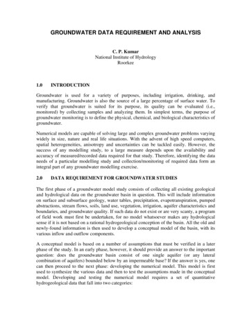
US / INTERNATIONALTyco Safety ProductsOne Stanton StreetMarinette, WI 54143-2542800-526-1079715-732-3465 CANADATyco Safety Products871 Equestrian Court Unit 1A,2nd FloorOakville, ON L6L 6L7 Canada877-992-6785905-847-0217BULLETINBulletin Number:2320Date:July 8, 2008TO:All PYRO-CHEM Restaurant System Distributors and OEM’sFROM:Product Management – Restaurant SystemsSUBJECT:KITCHEN KNIGHT II Nieco Broiler Protection – Model MPB 94 - with Catalyst OnlyPYRO-CHEM is pleased to announce KITCHEN KNIGHT II appliance-specific fire protection for the NiecoBroiler Model MBP 94 for low profile applications. This design was tested to offer overhead coverage protectionversus the chain broiler protection currently being utilized. This bulletin is a temporary supplement to theKITCHEN KNIGHT II Technical Manual (PN551274-4) dated March 1, 2006 and is not intended to replace therequirements and limitations outlined in the current manual. The information contained in this bulletin will beadded to the manual upon the next printing.Nieco Broiler: Model MPB 94 (109,590 Btu/hr Maximum)The following nozzle position and coverage limitations must be followed:Nozzle quantity.OneNozzle type.2LNozzle height.20 in. (508 mm)Nozzle location.6 1/2 in. (165 mm) inside from outside edge of the appliance topNozzle aim point.Aimed at center of catalyst2L NOZZLEBACKFRONT6 1/2 IN. (165 mm)FROM OUTSIDE EDGEOF THE APPLIANCEPRODUCTINPUTPRODUCTOUTPUT6 1/2 IN. (165 mm)FROM OUTSIDEEDGE OF THEAPPLIANCEBACKFRONTSIDE VIEWTOP VIEW008095008096If you should have any questions pertaining to this bulletin, please contact your Territory Sales Manager or callTechnical Services at 1-800-526-1079 or 1-715-732-3465.ULEX 3830
KITCHEN KNIGHT II Restaurant Fire Suppression ManualThis manual is intended for use with PYRO-CHEM KITCHENKNIGHT II Restaurant Fire Suppression Systems.Those who install, operate, recharge, or maintain these firesuppression systems should read this entire manual. Specificsections will be of particular interest depending upon one’sresponsibilities.Design, installation, recharge, and maintenance of the systemmust conform to the limitations detailed in this manual and performed by an individual who attended a PYRO-CHEM trainingprogram and became trained to install, recharge, design, andmaintain the PYRO-CHEM system.Fire suppression systems are mechanical devices. They needperiodic care. Maintenance is a vital step in the performanceof your fire suppression system. As such it must be performedin accordance with NFPA 96 (Standard for the Installationof Equipment for the Removal of Smoke and Grease-LadenVapors from Commercial Cooking Equipment) and NFPA17A (Standard on Wet Chemical Extinguishing Systems) byan authorized PYRO-CHEM distributor. To provide maximumassurance that the fire suppression system will operate effectively and safely, maintenance must be conducted at six-monthintervals, or earlier if the situation dictates. Twelve-year maintenance must include agent tank hydrostatic testing.PART NO. 551274-06PYRO-CHEM, KITCHEN KNIGHT, and the product names listed in this material are marksand/or registered marks. Unauthorized use is strictly prohibited.FOREWORDUL EX3830 ULC EX38302014-NOV-10 REV. 06
EXPLANATION OF SAFETY ALERTSUL EX3830 ULC EX3830REV. 06 2014-NOV-10KITCHEN KNIGHT II Restaurant Fire Suppression Manualp DANGER!Indicates a hazardous situation in which a person will experience serious personal injury or death if the situation is notavoided.! WARNINGIndicates a hazardous situation in which a person could experience serious personal injury or death if the situation is notavoided.! CAUTIONIndicates a hazardous situation in which a person could experience minor or moderate personal injury if the situation is notavoided.CAUTIONAddresses practices not related to personal injury, such asa system part malfunctioning, property damage, or system failure.NOTICEAddresses general practices or observationsrelated to system function that are not relatedto personal injury.
REVISION RECORDUL EX3830 ULC EX38302014-NOV-10 REV. 06 Page 1KITCHEN KNIGHT II Restaurant Fire Suppression ManualDATEPAGE2014-NOV-10 Complete manual hasbeen reformatted alongwith several revisedpages that containupdated technicalinformation. For clarity,all pages have beenchanged to Revision 06,regardless of previousrevision number.Technical informationchanges have beennoted with a revisionindicator (u).Indicates revised information.Indicates change in page sequence.REV. NO.DATEPAGEREV. NO.
REVISION RECORDUL EX3830 ULC EX3830Page 2 REV. 06 2014-NOV-10DATEPAGEIndicates revised information.Indicates change in page sequence.KITCHEN KNIGHT II Restaurant Fire Suppression ManualREV. NO.DATEPAGEREV. NO.
TABLE OF CONTENTSUL EX3470 ULC EX34702014-NOV-10 REV. 06 Page TOC-1KITCHEN KNIGHT II Restaurant Fire Suppression ManualSECTIONPAGES1. General InformationINTRODUCTIONTemperature LimitationsUL ListingULC ListingMEA ApprovalSECTIONPAGES1-11-11-11-11-1NOZZLESRUBBER BLOW-OFF CAPSSWIVEL ADAPTORNOZZLE AIMING DEVICEHORN/STROBE ASSEMBLYCOMPONENTS LIST2-112-112-112-122-122-132. ComponentsCYLINDERS & VALVEWET VALVE REBUILDING EQUIPMENTWet Valve Seal Rebuilding KitPressure Regulator AssemblyPressure Regulator Rebuilding KitModel VT-1 ToolCYLINDER BRACKETINGEXTINGUISHING AGENTMCH3 MECHANICAL CONTROL HEADECH3 ELECTRICAL CONTROL HEADNMCH3 MECHANICAL CONTROL HEADEN-MCU3 ENCLOSUREEN-S ENCLOSURE16 GRAM CO2 CARTRIDGEMB-P2 MOUNTING BRACKETPNEUMATIC ACTUATING CYLINDERSModel PAC-10DETECTION EQUIPMENTModel FLK-1Model FLK-1AModel FLH-1A-PC Fusible LinksThermal DetectorsFlexible ConduitRPS-M – REMOTE PULL STATION“QUIK-SEAL” ADAPTOR“COMPRESSION-SEAL” ADAPTOR“HOOD SEAL” ADAPTOR ASSEMBLYGAS SHUT-OFF VALVESGV Shut-off ValveEGVSO Gas Shut-off ValveCORNER PULLEYSSBP-1 Corner PulleyCBP-1 Corner PulleyWBP-1 Corner PulleyTEE PULLEYWIRE ROPEELECTRICAL SWITCHESSM-120 SOLENOID MONITORPIPE AND FITTINGSAGENT DISTRIBUTION HOSE ANDRESTRAINING CABLE KITSTAINLESS STEEL ACTUATION 2-92-92-92-92-92-102-102-102-112-112-113. System DesignGENERALNOZZLE COVERAGE AND PLACEMENTDuct ProtectionModularizing DuctTransition DuctsElectrostatic PrecipitatorPlenum ProtectionAppliance ProtectionDesign ChartFryersRange (Small)High-Proximity BackshelfRange (Large)Nozzle Positioning TableSmall WokLarge WokSmall GriddleLarge GriddleRadiant/Electric Char-BroilerLava Rock Char-BroilerNatural Charcoal Char-BroilerMesquite Char-BroilerSalamander BroilerUpright/Salamander BroilerChain BroilerTilt Skillet/Braising PanSPECIFIC APPLICATION BY MODELHenny Penny Fryer – Models 690, 691, 692Henny Penny Fryer – Models 580,581, 582, 590, 591, 592, 680, 682Nieco Broiler – Model MPB-84Nieco Broiler – Model JF94EBaker’s Pride BroilersPIPING LIMITATIONSGeneral Piping RequirementsDesign StepsDETECTOR PLACEMENTExhaust Duct(s)Electrostatic PrecipitatorCooking 24
KITCHEN KNIGHT II Restaurant Fire Suppression ManualTABLE OF CONTENTSUL EX3470 ULC EX3470Page TOC-2 REV. 06 2014-NOV-10SECTION4. System InstallationGENERALCYLINDER INSTALLATIONCONTROL HEAD INSTALLATIONSingle Cylinder InstallationMultiple Cylinder InstallationDETECTOR INSTALLATIONFusible Link DetectionFusible Links Without HangersFusible Links With Link HangersThermal DetectionSETTING THE CONTROL HEADMCH3/NMCH3 Control HeadECH3 Control HeadSOLENOID MONITOR INSTALLATIONIn Detection CircuitSolenoid Monitor When Used as aReset RelayREMOTE PULL STATION INSTALLATIONGAS SHUT-OFF VALVE INSTALLATION Mechanical Gas Shut-offValve InstallationElectrical Gas Shut-off Valve InstallationPULLEY TEE INSTALLATIONELECTRICAL (SNAP-ACTION) SWITCHINSTALLATIONPIPE AND NOZZLE INSTALLATIONINSTALLATION INSTRUCTIONS FORCASTERED/MOVEABLE EQUIPMENTUSING AGENT DISTRIBUTION HOSECritical Installation RequirementsAGENT DISTRIBUTION HOSE INSTALLATIONGeneral RequirementsInstallation RequirementsRestraining Cable InstallationFinal Installation Guidelines andCheckout ProceduresAgent Distribution Hose/RestrainingCable Six-Month MaintenanceBlank PageSYSTEM CHECKOUT AFTER INSTALLATIONModel MCH3/NMCH3 MechanicalControl HeadModel ECH3-24/120 ElectricalControl HeadTesting Thermal DetectorsTesting Remote Pull StationCompleting System CheckoutENCLOSURE INSTALLATION INSTRUCTIONS– MODEL EN-MCU3 AND MODEL EN-SEnclosure MountingFusible Link Detector 194-194-194-20SECTIONPAGESSetting the EN-MCU3Remote Pull Station InstallationGas Shut-off Valve InstallationElectrical (Snap-Action) Switch InstallationCylinder InstallationSingle Cylinder InstallationMultiple Cylinder InstallationSystem Checkout After InstallationFLEXIBLE CONDUIT INSTALLATIONDesign RequirementsInstallation RequirementsConnecting Flexible Conduit to ControlHead, Electrical Box, Pull Station, orMechanical Gas ValveConnecting Flexible Conduit to PulleyElbows, Pulley Tees, or Union FittingsInstalling Flexible Conduit Through aConduit OffsetFlexible Conduit SplicingTesting Pull Station/Mechanical Gas -244-264-274-294-315. System MaintenanceGENERALSEMI-ANNUAL MAINTENANCEANNUAL MAINTENANCE12-YEAR MAINTENANCE5-15-15-15-26. System RechargeGENERALSYSTEM CLEANUPSYSTEM RECHARGE6-16-16-1
SECTION 1 – GENERAL INFORMATIONUL EX3830 ULC EX38302014-NOV-10 REV. 06 Page 1-1KITCHEN KNIGHT II Restaurant Fire Suppression ManualINTRODUCTIONThis manual is intended for use with PYRO-CHEM KITCHENKNIGHT II Restaurant Fire Suppression Systems. Those whoinstall, operate, recharge, or maintain these fire suppressionsystems should read this entire manual. Specific sections willbe of particular interest depending upon one’s responsibilities.Design, installation, recharge, and maintenance of the systemmust conform to the limitations detailed in this manual andperformed by an individual who attended a PYRO-CHEM training program and became trained to install, recharge, design,and maintain the PYRO-CHEM system.Fire suppression systems are mechanical devices. They needperiodic care. Maintenance is a vital step in the performanceof your fire suppression system. As such, it must be performedin accordance with NFPA 96 (Standard for the Installationof Equipment for the Removal of Smoke and Grease-LadenVapors from Commercial Cooking Equipment) and NFPA17A (Standard on Wet Chemical Extinguishing Systems) byan authorized PYRO-CHEM distributor. To provide maximumassurance that the fire suppression system will operate effectively and safely, maintenance must be conducted at six-monthintervals, or earlier if the situation dictates. Twelve-year maintenance must include agent tank hydrostatic testing.The PYRO-CHEM KITCHEN KNIGHT II Pre-Engineered Systemutilizes a wet chemical agent specifically designed to suppressrestaurant cooking area fires. The system provides automaticactuation and can be manually actuated through a remotemechanical pull station. Upon actuation, the system dischargesa pre-determined amount of agent to the duct, plenum, andcooking appliances. The agent acts to suppress fires in threeways:1. The chemical chain reaction causing combustion is interrupted by both the agent itself and the resulting steamformation.2. The agent cools the fire bringing it below auto-ignitiontemperature.3. The agent reacts with hot grease forming a soap-like layer(saponification) that helps prevent the escape of combustible vapors, thus preventing re-ignition.The shutdown of all sources of fuel and electric power thatproduce heat to all equipment protected by the system isrequired upon system actuation. Make up or supply air fans,integral to the exhaust hood(s) being protected, shall be shutdown upon system actuation. Exhaust fan(s) in the ventilationsystem should remain on during system discharge as theyassist the dispersion of chemical through the ventilating system.The system is UL Listed with or without exhaust fan shutdown.The KITCHEN KNIGHT II and the KITCHEN KNIGHT RestaurantFire Suppression System are compatible as long as separateinstallation guidelines are followed per each system designmanual. Exception: The actuation limitations for the KITCHENKNIGHT II system may be utilized for the KITCHEN KNIGHTsystem. Also, control heads, prior to Model No. 3, may beutilized on KITCHEN KNIGHT II systems, provided that thelimitations used with those control heads are followed.Temperature LimitationsThe operating temperature range of the PYRO-CHEMKITCHEN KNIGHT II System is 32 F (0 C) minimum to120 F (49 C) maximum.UL ListingThe PYRO-CHEM KITCHEN KNIGHT II Restaurant FireSuppression System has been tested to the UL Standardfor Fire Extinguishing Systems For Protection of RestaurantCooking Areas, UL300 and Listed by Underwriters Laboratories,Inc.ULC ListingThe PYRO-CHEM KITCHEN KNIGHT II Restaurant FireSuppression System is listed by Underwriters Laboratories ofCanada (ULC). The ULC Listing No. is EX3830.MEA ApprovalThe PYRO-CHEM KITCHEN KNIGHT II Restaurant FireSuppression System has been approved for use by MEA(Material and Equipment Acceptance Division) for New YorkCity. The MEA Certification No. is 249-03-E.
SECTION 1 – GENERAL INFORMATIONUL EX3830 ULC EX3830Page 1-2 REV. 06 2014-NOV-10NOTES:KITCHEN KNIGHT II Restaurant Fire Suppression Manual
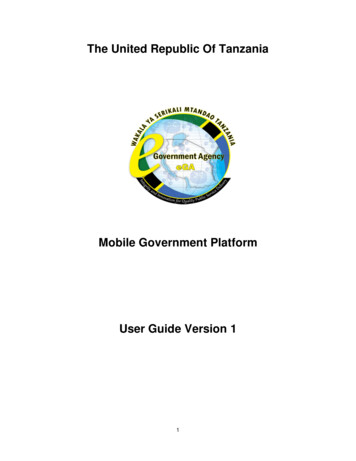
SECTION 2 – COMPONENTSUL EX3830 ULC EX38302014-NOV-10 REV. 06 Page 2-1KITCHEN KNIGHT II Restaurant Fire Suppression ManualCYLINDERS & VALVEThe PYRO-CHEM KITCHEN KNIGHT II System has availablefour different size cylinders: Models PCL-160 (Part No. 553163),PCL-300 (Part No. 551194), PCL-460 (Part No. 551193), andPCL-600 (Part No. 551196). Cylinder sizes are expressed interms of extinguishing agent capacity (i.e., the PCL-300 uses3.0 gallons (11.4 L) of extinguishing agent). The cylinder ismanufactured, tested, and meets DOT requirements. Cylinderscome pre-filled with extinguishing agent and are charged withdry nitrogen to a pressure of 225 psig @ 70 F (15.5 bar @21 C). Cylinder and valve assembly dimensions are shown inFigure 2-1.Figure 2-2006212PCWET VALVE REBUILDING EQUIPMENTWet Valve Seal Rebuilding KitAfter system discharge, the valve assembly must be rebuilt toensure proper future operation. The Wet Valve Seal Re build ingKit (Part No. 550698) should be used. It includes all componentsnecessary to properly rebuild the valve. See Figure 2‑3.Max.ABCDFlow Weight MountingModelin.in.in.in.PointlbBracketNo.(mm) (mm) (mm) (mm) Capacity (kg)UsedPCL-160 8.00 17.75 23.50 15.44534MB-15(203) (451) (597) (392)(15.4)PCL-300 8.00 25.06 30.81 22.7510 53MB-15(203) (637) (783) (578)(24.0)PCL-460 10.00 25.06 30.81 22.751583MB-15(254) (637) (783) (578)(37.6)PCL-600 10.00 35.81 41.56 33.5020108MB-1(254) (910) (1056) (851)(49.0)Figure 2-1002841PCAll cylinders utilize the same Wet Valve Assembly (Part No.551175). The wet valve assembly is a pressure sealed poppettype valve designed to provide rapid actuation and discharge ofagent. See Figure 2-2.Item Part No. Description1Valve Body2550705Conical Spring3550707Piston4550716Neck O-Ring5551236Pressure Gauge6550028Stem O-Ring7550802 Wet ValveAdaptorItem891011121314Part No. Description550386 Shrader ValveAss’y550714Valve Cap O-Ring550715Piston O-Ring550989Valve Stem551256 PressureRegulator551261Seal178516-32x3/8 ScrewFigure 2-3002906PCItem123456Part ionConical SpringNeck O-RingStem O-RingPiston O-RingValve StemValve Cap O-RingPressure Regulator AssemblyThe pressure regulator assembly (Part No. 550985) is availableif the complete regulator requires replacement (e.g. possiblethread damage).
SECTION 2 – COMPONENTSUL EX3830 ULC EX3830Page 2-2 REV. 06 2014-NOV-10KITCHEN KNIGHT II Restaurant Fire Suppression ManualWET VALVE REBUILDING EQUIPMENT (Continued)Pressure Regulator Rebuilding KitAfter system discharge and at hydrotest intervals, the pressureregulator must be rebuilt to ensure proper future operation. ThePressure Regulator Rebuilding Kit (Part No. 551061) should beused. It includes all components and instructions necessary toproperly rebuild the regulator. See Figure 2-4.In ValveBodySeal (PartNo. 551261)A#6-32 x 3/8 in. Screw(Part No. 17851)Internal O-Ring(Part No. 402745)PistonO-Ring(Part No.12837)Spring (PartNo. 551176)PistonBCExternal O-Ring(Part No. 551273)Model No. A#8-32 x 3/8 in.Holding Screw(Part No. 419045)Figure 2-4006103PCModel VT-1 Wet Valve ToolThe Model VT-1 Wet Valve Tool (Part No. 550788) is designedto facilitate the rebuilding of the wet valve assembly. It should beused to hold the wet valve piston while unscrewing the cap andstem assembly. See Figure 2-5.BCMB-1515.69 in.(399 mm)4.0 in.(102 mm)3.13 in.(7.9 mm)MB-120.44 in.(519 mm)4.0 in.(10\2 mm)2.13 in.(5.4 mm)Figure 2-6006842PCEXTINGUISHING AGENTThe agent used in PYRO-CHEM KITCHEN KNIGHT II Systemsis a potassium carbonate based solution that is extremely effective for grease-related kitchen fires. This agent is available forcylinder recharging in 1.6 Gallon and 3.0 Gallon containers. ForMSDS information, contact Tyco Fire Protection Products or visitwww.pyrochem.com.1.6 Gallon Shipping Assembly – Part No. 5531763.0 Gallon Shipping Assembly – Part No. 551188Figure 2-5002907PCCYLINDER BRACKETINGVertical bracketing of the PCL-160, PCL-300 and PCL-460 isprovided by the Model MB-15 Bracket Kit (Part No. 550054).Vertical bracketing of the PCL-600 is provided by the ModelMB-1 Bracket Kit (Part No. 550053). See Figure 2-6. These kitsmust be ordered separately with each cylinder/valve assembly.Cylinder installation instructions are provided in the installationsection of this manual.! CAUTIONPrecautions must be taken when handling and transferringwet agents as they are caustic in nature. Goggles must beworn at all times. If any agent gets into the eyes, they shouldbe flushed with clean water for 15 minutes and a physiciancontacted. If any agent contacts the skin, it should be flushedwith cold water to prevent irritation. The agent is electricallyconductive. Care must be taken to thoroughly clean up anyagent discharged around electrical appliances before turningthe power on.After system discharge, agent must be cleaned up immediatelywith hot, soapy water to prevent corrosion of affected surfaces.
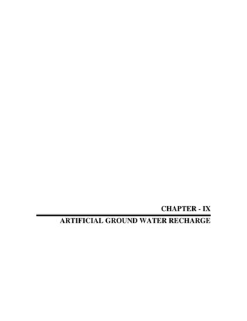
KITCHEN KNIGHT II Restaurant Fire Suppression ManualSECTION 2 – COMPONENTSUL EX3830 ULC EX38302014-NOV-10 REV. 06 Page 2-3MODEL MCH3 – MECHANICAL CONTROL HEADThe Model MCH3 Mechanical Control Head (Part No. 551200)is a fully mechanical control head which can be connected tothe PCL-160/300/460/600 cylinder valve. This control head willsupport a fusible link detection system, a remote mechanical pullstation (Model RPS-M), and a mechanical or electric gas shutoff valve. A micro electric switch (Model MS-SPDT, MS-DPDT,MS-3PDT, or MS-4PDT) can be ordered separately and fieldinstalled. It is equipped with a local manual control handle thatallows for mechanical system actuation. Operation of the localmanual control requires removing the pull pin and rotating thehandle clockwise. The Model MCH3 control head can actuate amaximum of five cylinders with the 16 gram CO2 cartridge. SeeFigure 2-7.MODEL MCH3 CONTROL HEADPULL PIN, TURN HANDLESETFIREDTO RELEASE FIRESUPPRESSION SYSTEMPYRO-CHEMONE STANTON STREETMARINETTE, WI 54143-2542Figure 2-8004789PCMODEL NMCH3 – MECHANICAL CONTROL HEADThe Model NMCH3 Mechanical Control Head (Part No. 551203)is a fully mechanical control head which can be connected tothe PCL‑160/300/460/600 cylinder valve. This control head willsupport a fusible link detection system, a remote mechanical pullstation (Model RPS-M), and a mechanical or electric gas shutoff valve. An electrical (snap-action) switch (Model MS-SPDT,MS‑DPDT, MS-3PDT, or MS-4PDT) can be ordered separatelyand field installed. There is no local manual actuation for theModel NMCH. The Model NMCH3 control head can actuate amaximum of five cylinders with the 16 gram CO2 cartridge.Figure 2-7004790PCMODEL ECH3 – ELECTRIC CONTROL HEADThe Model ECH3 electric control head is an electrically operatedcontrol head which can be connected to the PCL-160/300/460/600cylinder valve. This control head will support an electric thermaldetection system, a remote mechanical pull station (ModelRPS-M), and an electric gas shut-off valve. It will not supporta fusible link detection system. An electric (snap-action) switch(Model MS-DPDT) is included.The Model ECH3 control head is available in both 120VAC(Model ECH3-120 (Part No. 551202)) and 24VDC (ModelECH3-24 (Part No. 551201)). It is equipped with a local manualcontrol handle that allows for mechanical system actuation.Operation of the local manual control requires removing the pullpin and rotating the handle clockwise. The Model ECH3 controlhead can actuate a maximum of five cylinders with the 16 gramCO2 cartridge. See Figure 2-8.Figure 2-9006843PCMODEL EN-MCU3 ENCLOSUREThe Model EN-MCU3 Enclosure (Part No. 551208) is used forvertical mounting of a single PCL-160, PCL-300 or PCL-460.The EN-MCU3 also includes a mechanical control unit, eliminating the need for a Model MCH3 control head. See Figure 2-10.Note: The PCL-600 cannot be mounted in an EN-MCU3.Note: When utilizing electric detection, it is recommended thatthe Model ECH3-24 electric control head be used with eitherthe AUTOPULSE 542R Control Panel (Part No. 433607) orthe AUTOPULSE Z-10 Control Panel (Part No. 430525). If theECH3-120 control head is to be utilized, it must be used withSolenoid Monitor, Model SM-120 (Part No. 550302), along witha UL Listed 1A, 120VAC power supply (by others), in accordance with NFPA 17A, NFPA 96, and the local authority havingjurisdiction.Figure 2-10002845PC
SECTION 2 – COMPONENTSUL EX3830 ULC EX3830Page 2-4 REV. 06 2014-NOV-10KITCHEN KNIGHT II Restaurant Fire Suppression ManualMODEL EN-S ENCLOSUREPNEUMATIC ACTUATING CYLINDERSThe Model EN-S Enclosure (Part No. 550966) is used for verticalmounting of a single PCL-160, PCL-300 or PCL-460 when it isused as a secondary agent cylinder in a system. Dimensionsare the same as the Model EN-MCU3 enclosure (see Figure2-10). The EN-S has no control mechanism, and must be usedin conjunction with a Model EN‑MCU3 enclosure or a ModelMCH3/ECH3 control head. Note: The PCL-600 cannot bemounted in an EN-S enclosure.Model PAC-1016 GRAM CO2 CARTRIDGEThe Model PAC-10 (Part No. 550104) is a pneumatic actuatingcylinder that can actuate a maximum of ten agent cylinderssimultaneously. The Model PAC-10 includes a DOT 4BA350cylinder pressurized with dry nitrogen to 350 psig @ 70 F(24.1 bar @ 21 C), a brass valve with pressure gauge, anda wall mounting bracket. A Model MCH3, NMCH3, or ECH3control head must be purchased separately and connected tothe PAC-10 to open the valve. See Figure 2-12.The 16 Gram CO2 Cartridge (Part No. 551059) is required topneumatically actuate the tank valve. The cartridge is installed inthe control head on top of the tank valves. The cartridge shippingassembly contains six cartridges.MODEL MB-P2 – CONTROL HEAD MOUNTING BRACKETThe Model MB-P2 Mounting Bracket (Part No. 550853) mustbe used to mount the Model MCH3, NMCH3, or ECH3 controlheads if the control head is not mounted directly on a cylindervalve. See Figure 2-11.Figure 2-12002847PCFigure 2-11002846PC
KITCHEN KNIGHT II Restaurant Fire Suppression ManualSECTION 2 – COMPONENTSUL EX3830 ULC EX38302014-NOV-10 REV. 06 Page 2-5DETECTION EQUIPMENTModel FLH-1 AssemblyModel FLK-1 AssemblyThe Model FLH-1 Fusible Link Hanger Assembly (Part No.550876) is an accessory designed to simplify the installationof fusible links in the fusible link line. It can be used with theModel FLK-1 fusible link kit (kits must be ordered separately).The fusible link hanger makes it possible to install fusible linkswithout cutting and crimping loops in the fusible link line for eachlink. They are available in packages of 25 (FLH-25) only. SeeFigure 2-14.The Model FLK-1 Assembly (Part No. 550131) includes a 10 in.(254 mm) steel bracket, two 1/2 in. EMT connectors, two cablecrimps, and two “S” hooks. Fusible links must be ordered separately. See Figure 2-13.Model FLK-1A AssemblyThe Model FLK-1A Assembly (Part No. 550132) includes an8 in. (203 mm) steel bracket, two 1/2 in. EMT connectors, twocable crimps, and two “S” hooks. Fusible links must be orderedseparately.Figure 2-13002849PCFigure 2-14002850PC
SECTION 2 – COMPONENTSUL EX3830 ULC EX3830Page 2-6 REV. 06 2014-NOV-10KITCHEN KNIGHT II Restaurant Fire Suppression ManualA-PC Fusible LinksThe A-PC fusible link is designed to separate at a specifictemperature, releasing tension from the fusible link line, causingsystem actuation. See Figure 2-15.Note: A transient rush of warm air up to 40 F (4 C) perminute may expand the shell, but not enough to trigger the unit.Temperature increases over 40 F (4 C) per minute however,may initiate an alarm condition.Note: When possible, temperature readings should be takenat each detector location to determine optimum fusible linktemperature ratings. Temperature can be recorded usingeither a Maximum Registering Thermometer (Part No. 15240)temperature tape (by others), or any other accurate thermometerthat will record the maximum temperature experienced at thedetector location.6 IN. LEADS(152 mm))1/2 – 14 NPT1 IN.HEX4.9 IN.(124 mm)3.7 IN.(93 mm)5/8 IN.(16 mm)Figure 2-16007354Flexible ConduitFigure 2-15002851PCAfter determining the maximum ambient temperature at thefusible link location, select the correct fusible link according tothe temperature condition chart below:Fusible LinkShippingAssemblyTemperaturePart No.RatingTo Be UsedWhere TemperatureDoes Not Exceed439227 (10)165 F100 F (38 C)439229 (10)280 F (138 C)439228 (10)439230 (10)439231 (10)439232 (25)(74 C)212 F (100 C)360 F (182 C)450 F (232 C)500 F (260 C)439104Pre-Fed Flexible Conduit Assembly –50 ft (15.2 m)435959290 F (143 C)436063400 F (204 C)79827434347360 F (182 C)436150Part NumberTD-225155 F (68 C)13976TD-450380 F (193 C)13974530 F (277 C)Flexible Conduit – 500 ft (152.4 m)225 F (107 C)MaximumThermalDetector AmbientModel ting thermal detectors are normally open,mechanical contact closure switches designed to operate at afactory preset temperature. They are available in four presettemperatures which meet NFPA standards and are UL Listedand FM Approved. After determining the maximum ambienttemperature at the thermal detector location, select the correctthermal detector according to the temperature condition chartbelow:255 F (124 C)Part No.434525150 F (66 C)Thermal DetectorsTD-325Flexible Conduit can be used with the Mechanical Pull StationAssemly (Part No. 551074) and Mechanical Gas Valves.Flexible Conduit eliminates the need for rigid EMT conduit in themechanical pull station and gas valve lines, significantly reducing the overall installation time.139751397155813Flexible Conduit – 500 ft (152.4 m) andWire Rope – 500 ft (152.4 m)Flexible Conduit Strain Relief (50-Pack)Flexible Conduit Insert (50-Pack)Conduit Offset (6-Pack)P-Clip (50-Pack)Compression Union, 1/2 in.1/2 in. Compression Connector
SECTION 2 – COMPONENTSUL EX3830 ULC EX38302014-NOV-10 REV. 06 Page 2-7KITCHEN KNIGHT II Restaurant Fire Suppression ManualMODEL RPS-M – REMOTE MECHANICAL PULL STATION“COMPRESSION-SEAL” ADAPTORRemote manual control for the Model MCH3, NMCH3, orECH3 control head is provided by the Model RPS-M RemoteMechanical Pull Station (Part No. 551074). It is connected tothe system control head by stainless steel cable. This cable isenclosed in 1/2 in. EMT conduit with corner pulleys or flexibleconduit with bends and/or corner pulleys at each change indirection. The remote mechanical pull station shall be located atthe point of egress. See Figure 2-17.This adaptor is a mechanical bulkhead fitting that produces aliquid-tight seal around pipe and conduit when installing distribution piping and detection conduit through restaurant hoods andducts. The “Compression-Seal” Adaptor is a straight-throughdesign requiring no cutting or threading of conduit or pipe. Theadaptor is available for EMT conduit size of 1/2 in. (Part No.79152). See Figure 2-19. “Compression-Seal” Adaptor ShippingAssembly must be ordered as stated below:ShippingAssemblySizePart No.Qty.1/2 in. EMT Conduit7915324Hole SizeRequired1 1/8 in.Compression NutAdaptor BodyGasketLockwasherNutFigure 2-19“HOOD SEAL” ADAPTOR ASSEMBLYFigure 2-17002852PC“Quik-Seal” AdaptorThe “Quik-Seal” adaptor is a listed mechanical bulkhead fittingthat produces a liquid-tight seal around both distribution pipingand detection conduit which runs through restaurant hoodsand ducts. The “Quik-Seal” adaptor accepts threaded pipe orconduit. The adaptor is available for 3/8 in. and 1/2 in. pipe orconduit sizes. When using with EMT conduit, a conduit connector must be installed in each end of the adaptor. The “Quik-Seal”Adaptor Shipping Assembly can be ordered in single or packageof 24. See Figure 2-18.ShippingAssemblyHole SizeSizePart No.Qty.Required3/8 in.55085711 1/8 in.3/8 in.550858241 1/8 in.1/2 in.1/2 in.5508595508601241 1/8 in.1 1/8 in.Adaptor BodyGasketLockwasherNutFigure 2-18000154This adaptor is a mechanical bulkh
KITCHEN KNIGHT II Restaurant Fire Suppression Manual UL EX3830 ULC EX3830 2014-NOV-10 REV. 06 FOREWORD This manual is intended for use with PYRO-CHEM KITCHEN KNIGHT II Restaurant Fire Suppression Systems. Those who install, operate, recharge, or maintain these fire suppression systems should read this entire manual. Specific