Transcription
Large Bolted JointsTESTS OF A490 BOLTS(Preliminary Report)byGordon SterlingJohn W. FisherMarch 1964
SYNO-PSISPresented in this report are the results of calibration testst,of individual ASTM A490 alloy steel bolts.The b'olts tested were 7/8 in.nominal diameter. ' Results of'twenty direct tension and thirty torquedtension tests are reported.This is a preliminary report and will eventually be re-writtento include information on similar tests conducted on the same bolt lots'at, the University of Illinois.INTRODUCTIONAt the February 14, 1963 meeting of Committee 15 of the ResearchCouncil on Riveted and Bolted Structural Joints, it was recommended thatLehigh University and the University of llinoisconduct tests on boltsfrom the same 'lot to determine if -testing procedures constitute a variable.Each university was to test bolts in direct tension and torquedtension using its own standard calibration procedures.This report discusses the results of the tests conducted atLehigh.The bolts were purposely ordered near the minimum specifiedtensile strength.-1-
TEST PREPARATIONTwo lots of 7/8 in. diameter, heavy hexagon head, A490 boltswere tested.'B'efore testing', all bolts were st'arriped with a lot designationand bolt nu ber.,of the' head andIn additio , each ,bolt had ho es ril1ed in the centersnut 'ends ,toaccommodate the C-frame extensometer. lts designate as AB ot· were'9 in. long wit 1 in. of cutthread.'Those labelled' Lot' :U were 5 in. long with 1% in. of rolledthread.Inal tests, one hardened washer was used under .n A194 Grade2Hnut· (heavy hexagon).ofLot hread'Each lot w s tested with 1/8 in. and 9/16 in.in ·the grip . This gave grip lengths of 8\ and 8-11/16 in. forAB. bolts, .and 4-1/8 in. and 4-9/16 in. grip for the, LI bolts.A representative sample of twenty bolts and nuts from the ABlot were'checked for tolerance by using the NC2A go and no-go ring gagesand the NC2Bable. oand no-go plug gages.All specimens tested were accept-The AB lot bolts were received with a light coating of shipping oil.The L1 lot bolts were received with a greasy film, but were not, as'well lubricated as the AB bolts.with the NC2A gages.This lot of bolts was not checked'The, same keg of nuts and washers was used in thetests of both the AB and LI lots.-2-
TEST PROCEDUREa. ORQUEDTENSION TESTSSpecimens from both lots were tested in the Model M SkidmoreWilhelm calibrating device.Ten bolts from the L1 lot were also testedin a solid block of' A440 steel.For all tests conducted in the Skidmore-Wilhelm calibratorthe nut was turned by using a hand wrench until a lI'snug" tension often kips was reached in the bolt.Bolt load, elongation and turn-of-the-nu,t (in degrees) measurements were taken at 5 and 10 kips.The nutwas then rotated in 45 increments (1/8 tur'n-of-the-nut) with a pneumatic impact wrench until failure oc'curred either by fracture or bythread stripping.Bolt elongation and load data were taken at each45 increment of nut rotation.From the tests doneinthe Skidmore-Wilhelm device a meanelongation at a "snug" lo'ad of ten kips was determined for the L1 lotspecimens.This mean elongation was applied tothos specimens beingtested to failure in the solid A440 steel block by using a hand wrenchto turn the nut.in rements,The bolt was then tested b . turning the nut', in 45 using a pneumatic impact wrench.Bolt elongation measure-ments were taken at -each posi tioIJ, of, nut rotation.al1owe This procedu'rea direct comparison of the nut rotation VB. elongation charac-teristics of bolts tested by torquing in a block of A440 steel and inthe less rigid Skidmore-Wilhelm device.-3-
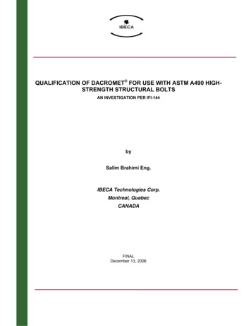
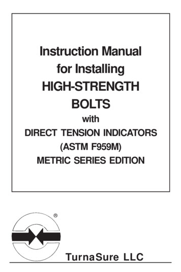
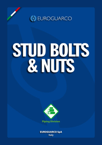
-4.,,b. DIRECT TENSION TESTSAs. a preliminary check the bolt being tested was loaded to thespecified proof load and then unloaded to check the ASTM requirement ofminimum 'permissible set (0.0005 in.).No bolts were rejected by thistest. ,The 'bolt wa's ·then' reloaded and elongation readings were, taken. at ten kip interva1s until the inelastic range was reached.At thispoint load readings were taken for every 0.01 in. of elongation in the. bolt . The direct tension tests were conducted in a 300 kip Baldwinhydraulic testing machine at a, strain rate of approximately 0.01 in. per'minute.A detailed description of the procedures used, in the calibratingof bolts is given in Reference 1.The reader is referred specifically toFigures 1 and 2 of this ,report for the specific set ups used in thedirect and torqued tension tests liEST RESULTSTable 1 and Figures 1 throughU summarize the test results.Theactual test points are given on most figures, and, therefore, Table 1merely indicates the significant mean values determined from all the tests.The 'specified proof load'for these 7/8 in. diameter, A490 bolts is1) John L. Rumpf ,and John W. Fisher"Calibration of A325 Bolts", Journal of the Structural Division,Va 89, No. ST6, Prec. Paper 3731, December, 1963, pp. 215-234. 5.45ASC ,
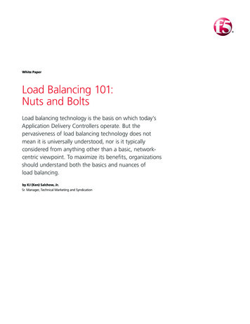
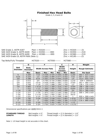
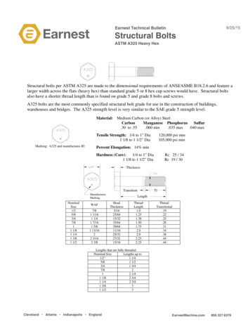
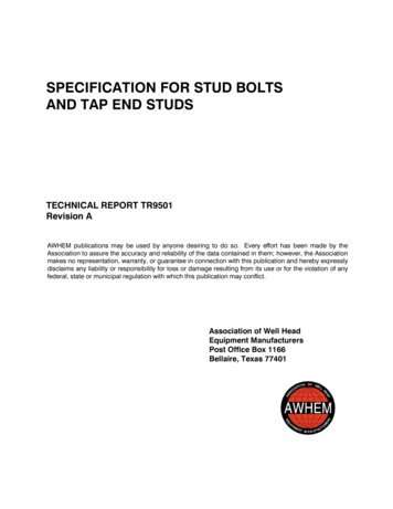
-5-kips, (i,e. the loadtowhich the bolt may be loaded so that after un-loadi.ng there is no more than 0.0005i .permanent set), andthe speci-fied minimum ultimate load is 69.3 kips.All the ,AB lot bolts failedFour failure 'modes were noticed.in the direct tension tests on a jagged diagonai through the threads.Two of the AB lot bolts tested in torqued tension with 1/8 in. thread ingrip failed by thread stripping as did two L1 bolts in direct tension'with the same amount 0, thread under the nut.In all four cases, thenut and bolt thread was so badly damaged that it was impossible to tellwhich thread had originally failed.The LI specimens tested in directtension with 9/16 in. thread in grip failed on a jagged diagonal asnoticed with the AB direct tension tests.However, three bolts with1/8 in. thread in the grip, failed on a level plane, through the threads,The other two LIat the juncture of the thread ·runout and bolt shank.bolts failed in the diagonal manner previously noted.All bolts testedin torqued tension (with the exception of the two AB lot bolts thatstripped) failed by "twisting off" on' a level plane through the firstthread under the nut at the time of failure.Figures 1 through 4 relate the load-elongation characteristicsof the bolts tested in direct and torqued tension.In all cases boltstested with 1/8" thread in grip gave.greater ultimate load than boltsfrom the same lot tested in the same manner with 9/16" thread' in grip;however, the specimens with 9/16" thread in grip sustained greater deformations before failure.
-6Figure 5 'shqws a typical relationship between the direct andtorqued tension tests.'Bo'1ts tested in direct tension gave greaterulti mate loads and sustained greater deformations to failure than did thosetested in torqued tension.Bolts tested' in the' solid A440 steel blo.ck gave greater loadsfor, fewe"r turns" as,isindicated in Fig. 6.Although there is, a broadscatter of the data associated with each test there is a definite separationof' 'the two mean curves.The bolt load is related to the number of turns from a "snug"bolt load of 10 kips in Figs. 7, 8, 9 and 10.The data s,hown in Figse7 and 8 refers to tests conducted in the Skidmore-Wilhelm calibrator.Figure 8 presents the results of tests done in a solid A440 steel block.The mean urvesfrom ;Figs. 8 and 9 (with 1/8" thread in grip) are plottedin Fig. 10 to compare with results of tests on A325 bolts(l).The "snug"load for the' A325 bolts was 8 kips.The load-elongation relationship of A490 and A325 bolts torquedin the Skidmore-Wilhelm calibrator areco paredin Fig. 11.7/8" x 9-!" bolts there is practically no difference at For "theturn from snug o(Again, for the A325 bolts "snug" was defined as 8 kips whereas for theA490 "snug" was 10 kips).The effect of exposed thread under the nut is given in Fig. 12and compared with results obtained on A325 bolts(l).This plot showsthat the A325 bolts ,sustain slightly more rotation to failure than do the"A490 bolts, especially at 9/16" thread in. grip.
CONCLUSIONSThe following conclusions are based on the results of 50 testsof individual bolts.(Twenty 7/8" x 9 " bolts and thirty 7/8" x 5 bolts).These results and conclusions are ,not greatly different from those'reported in a more comprehensive study of A354 alloy steel bolts(2).Similar results and conclusions, based on a limited number of tests,were also eportedin Ref. 3.'1. Bolts from the, same lot, and' with the' same amount of ,threadin grip, gaveB'greater ultimate strength in direct tension .tests thanwas achieved in torqued tension tests.For the AB l?t specimens thisincrease was 10 to 15 percent of the ultimate torqued, tension value, andfor the L1 lot bolts the increase was about 26 '·percent.'2. A lesser amount of thread in grip gave anultimate bolt strength in both the(SeiFigures 1 totorqu din reasein theand direct tension tests.4).3. For specimens with 1/8 in,. thread in grip the LI lot boltsrequired in average of1 turns from "snug" to failure; the AB lot bo1tsneeded an average of 1-3/8 turns.With 9/16 in. thread under the nutthis requirements increased to 1-5/8 and 1-3/4 turns for the LI and Alllot bolts respectively.Thus an increase from 1/8 in. to 9/16 in. threadin grip required an additional 3/8 turn' to failure for both bolt lots.(2) Richard J. Ch istopher and John W. Fisher"Calibration of A354 Bolts", Fritz' Engineering Laboratory Report No0288.9, March 1963.(3) E. Chesson, Jr. and W. H. Munse ."St\ld'ies of the B haVior of High Strength Bolts and Bolted Joints",Dept. ·of Civil Engineering, University of Illinois, Urbana, Illinois,Dec. 1963'-7-
-8-4. The'ave·r geload at turn from "snug" was less than thespecified proof load for both lots tested in the Skidmore-Wilhelm device.Three o the ten 5 , in. long LI lot bolts tested did give loads greaterthan. the ·specified proof load (55.45 kips) atthe AB lot bolts reached proof load at % turn from snug.turn from snug e(SeeNone ofFigs 2arid 4, ,and 7 and 8).5. Figure 6 indicates that the LI specimens, with 1/8" thread ingrip, torqu'ed in solid steel did reach proof load at turn from "snug".,Also this plot shows that, to· achieve the same bolt elongation) fewer turnsof the nut are required in specimens torqued in the solid steel blockthan is required forIf oneassume t osetested in the less rigid Skidmore-Wilhelm device.that the load vs'. elongation characteristics of the bolts,tested in torqued tension, are not' influenced by the material gripped,then (from Fig. 6) one observes that the bolt load at tu nabove proof load for those tested in the solid steel block.shows that proof load was also reached atqued in solid steel with 9/16"t read nis indeedFigure 8% turn for most specimens torgrip.6. The A325 and A490 bolts tested in the Skidmore-Wilhelm gavesubstantially the same load-turns relationship up to the elastic limitof the A325 bolts.(With such a broad scatter of data (see Figs. 7 and 8)it is strictly fortuitous that the mean curves fallon the exact sameline However, in the" elastic range of the bolts one would expectthe mean curves to be veryclose 7. The· 7/8 x 9 " A490 and A325 bolts (with similar amounts ofexposed thread under the nut,) behaved similarly into quedthe A490 bolts merely going to a higher "plateau".However, ,for the shortertension tests, withbolts the A490 tests indicate a relatively quick load drop off as comparedto the A325 bolts.Note that at turn from snug the load in the long boltswas approximately the same regardless of typee (See Fig. 11).
- 9-TABLE 1A490' BOLTS - 7/8" DIAMETERDIRECT TENSIONABBolt LotNominal GripThread in Grip'ins.8%ins . 1/8.Noe of Specimens TestedABTORQUED TENSION (inSkidmore Wilhelm)L1L1ABAB8-1 8-11/16 4-1/8 4-9/16 8tL1LI4-1/8 4-9/169/161/89/161/855555555.9/161/89/16Mean Ult. Loadkips73.270 876.072.165.461.861.158.4Std. Dev. from Ult. Loadkips1.59;1.690.540.172.802.182.803.00Mean Eloug. at Ult.ins.0.0779 0.0846Mean Rupture Loadkips65Mean Elong. after ruptureins.Mean Elong. at Proof Loadins.% Min. Spec. Ult. LoadMean Load at Turn0.051 0.0650.053 0.070 0.026 0.0316167520.120.180.137 0.245 .0.080.0280.0290.015 0.01710610211059400.114 0.075 0.110.028 0.031 0.016 0.01841.1 53.41-3/8 1-3/4 1% '1-5/80.900.870.800.77200048.8Ave. Turns to Failureoo234104kips(Torqued Tension ·Ult)'(Direct Tension UIto)No. of Stripping Failures50050.0TORQUED TENSION (insolid block)L1Thread in GripNo. of Strippingin o ailuresMean Elong. after Rupturein.Ave. Turns to "Snug" from "Finger Tight"Ave. Turns,to Failure' from "Snug"Ave. Turns to Proof Load from "Snug"Proof Load 55.4S kSpecified Minimum Ult. Load 69.3 kLI1/89/1600'.09'6.10.20.281.301.440.290.41
liS Thread in Grip80--t -tf- . .-. j in.Sp d Ultimate60Proof Load,- -55.45 kips --BOLT LOAD(kips)40gripI--wi. 8x9 i bolts, CutThreads20Jo.02-9-L1- - Fracture of Boltt thread in· grip.04.06.08 .10.12BOLT ELONGATION (inches)FIG o 1DIRECT TENSION CALIBRATION AB-LOT-BOLTS.14.16
80lIe Thread in Gripo60.1.-'proof JD0.9, 5.45 kips-- ------ --.- -- - . - ?- 1-.9"6T hreod in GripBOLT LOAD(kips)--Q- -40i'2 T;I urn- 0 f Nut f rom .SnugIII'la x9 lti bolts, CutThreads- -, - -20·.0.02.04.06BOL Flf}g 2TORQUED.08Fracture of Bolt.10.12ELONGATION (inches)TE SIONCALIBRATION At1-LOT SOLTS.14
.-.-.-aThread in Grip -,BOLT LOADe .1. . - II' .-tZ : -.9'r6ThreodPrO t 55.45 kips-.-.'. .: .d69.3kips,M n. SpecifiedUlti.mate·· Load.-l/8060. .' ,--'-. -,. '--. -.--- .in Grip. (kips)407,20o .02.0-4.06X 5 2 bolts, Rolled.06Threads!IQBOLT ELONGATION -(inches)FIG. 3 DIRECT TENSION CALIBRATION LI-LOT BOLTS.12.-.14I
80·"iThread in Grip60 Proof Load ,55.4 kips--------BOLT LOAD "(kips)-40 - t-. -rl.:' .9·116 Thread n "Grip«20Y8 x 5 2· bolts, Rolled ThreadsUo.02.04".06.08.10.12.14 .BOLT ELONGATION (inches)FIG o "4TORQUED TENSION CALIBRATION LI-LOT BOLTSf"' f r
- 80Direct TniQl'ee-- " e. Proof Lood . -55.45 kips \-60:BOLT LOAD(kips)40-4-. Torqued inSkidmore Wilhelm'l8X5 2 Bolts 8Thread in Grip20--o.02.04.06.08.10' 12.BOLT ELONGATION (inches
t, of individual ASTM A490 alloy steel bolts. The b'olts tested were 7/8 in. nominal diameter. ' Results of'twenty direct tension and thirty torqued tension tests are reported. This is a preliminary report and will eventually be re-written to include information on similar tests conducted on the same bolt lots 'at,the University of Illinois. INTRODUCTION At the February 14, 1963 meeting of .