Transcription
Standard Method of Test forSurface Resistivity Indication ofConcrete’s Ability to ResistChloride Ion PenetrationAmerican Association of State Highway and Transportation Officials444 North Capitol Street N.W., Suite 249Washington, D.C. 20001www.salmanco.comCopyright American Association of State Highway and Transportation Officials-- , ,,,, , , ,,,,,, - - ,, ,, , ,, ---Provided by : www.spic.irAASHTO Designation: T 358-151
Standard Method of Test forSurface Resistivity Indication ofConcrete’s Ability to ResistChloride Ion PenetrationAASHTO Designation: T 358-151Provided by : www.spic.ir-- , ,,,, , , ,,,,,, - - ,, ,, , ,, ---1.SCOPE1.1.This test method covers the determination of the electrical resistivity of water-saturated concreteto provide a rapid indication of its resistance to the penetration of chloride ions. This test methodis applicable to types of concrete where correlations have been established between this testprocedure and long-term chloride diffusion procedures such as those described in ASTM C1556.Examples of such correlations are discussed in the reference shown in Section 15.2.1.2.The values stated in SI units are to be regarded as the standard.1.3.This standard does not purport to address all of the safety concerns, if any, associated with its use.It is the responsibility of the user of this standard to establish appropriate safety and healthpractices and determine the applicability of regulatory limitations prior to use.2.REFERENCED DOCUMENTS2.1.AASHTO Standards: R 39, Making and Curing Concrete Test Specimens in the Laboratory T 23, Making and Curing Concrete Test Specimens in the Field T 24M/T 24, Obtaining and Testing Drilled Cores and Sawed Beams of Concrete T 277, Electrical Indication of Concrete’s Ability to Resist Chloride Ion Penetration2.2.ASTM Standards: C670, Standard Practice for Preparing Precision and Bias Statements for Test Methods forConstruction Materials C1202, Standard Test Method for Electrical Indication of Concrete’s Ability to ResistChloride Ion Penetration C1556, Standard Test Method for Determining the Apparent Chloride Diffusion Coefficientof Cementitious Mixtures by Bulk Diffusion3.SUMMARY OF TEST METHOD3.1.This test method consists of measuring the resistivity of 200-mm (8-in.) or 300-mm (12-in.)nominal length and 100-mm (4-in.) or 150-mm (6-in.) nominal diameter cylinders or cores by useof a 4-pin Wenner probe array. An alternating current (AC) potential difference is applied by thesurface resistivity apparatus at the outer pins of the Wenner array generating current flow in theconcrete. The resultant potential difference between the two inner pins is measured. The currentused and resultant potential along with the affected sample area are used to calculate the resistivitywww.salmanco.comTS-3cT 358-1 2015 by the American Association of State Highway and Transportation Officials.Copyright American Association of State Highway and Transportation OfficialsAASHTO
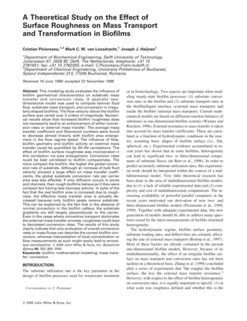
of the concrete. The resistivity, in kilohms-centimeters (kΩ-cm), has been found to be related tothe resistance of the specimen to chloride ion penetration.4.SIGNIFICANCE AND USE4.1.This test method covers the laboratory evaluation of the electrical resistivity of concrete samplesto provide a rapid indication of their resistance to chloride ion penetration. Wenner probemeasurements have shown good correlations with other electrical indication tests such as theT 277 and the ASTM C1202 tests. In most cases, the electrical resistivity results have shown goodcorrelation with chloride exposure tests, such as ASTM C1556, on companion cylinders cast fromthe same concrete mixtures (see references in Sections 15.2, 15.4, and 15.5).4.2.This test method is suitable for evaluation of materials and material proportions for designpurposes, as well as for research and development.4.3.The qualitative terms in the left-hand column of Table 1 should be used in most cases unlessotherwise noted by the specifying agency. The numerical results (resistivity, in kΩ-cm) from thistest method must be used with caution, especially in applications such as quality control andacceptance testing.Table 1—Chloride Ion PenetrationChloride IonPenetrationSurface Resistivity Test100-by-200-mm (4-by-8-in.) Cylinder150-by-300-mm (6-by-12-in.) Cylinder(kΩ-cm)(kΩ-cm)a 1.5a 1.5HighModerateLowVery lowNegligible 1212–2121–3737–254 254 9.59.5–16.516.5–2929–199 199a Wenner probe tip spacing4.4.Provided by : www.spic.ir-- , ,,,, , , ,,,,,, - - ,, ,, , ,, ---The details of the test method apply to 100-mm (4-in.) and 150-mm (6-in.) nominal diameterspecimens. Other specimen diameters may be tested with appropriate changes to the Wenner probetip spacing and the correction factor in the calculating equation. (See reference in Section 15.3.)www.salmanco.comTS-3cT 358-2 2015 by the American Association of State Highway and Transportation Officials.Copyright American Association of State Highway and Transportation OfficialsAASHTO
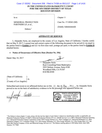
Provided by : www.spic.ir5.INTERFERENCES5.1.This test method can produce misleading results when calcium nitrite has been admixed into aconcrete. The results from this test on concrete mixtures including calcium nitrite indicate lowerresistivity values, that is, lower resistance to chloride ion penetration, when compared to tests onidentical concrete mixtures (controls) without calcium nitrite. However, long-term chloridediffusion tests indicate the concretes with calcium nitrite were at least as resistant to chloride ionpenetration as the control mixtures.Note 1—Other admixtures might affect results of this test similarly. Long-term diffusion tests arerecommended if an admixture effect is suspected.5.2.Sample curing condition is known to affect the resistivity of the solution in the pore structure (seeSection 15.4). Lime-water curing on average reduces resistivity by 10 percent.5.3.Because the test results are a function of the electrical resistance of the specimen, the presence ofreinforcing steel or other embedded electrically conductive materials may have a significant effect.The test is not valid for samples containing reinforcing.5.4.Sample age may have significant effects on the test results, depending on the type of concrete andthe curing procedure. Most concretes, if properly cured, become progressively and significantlyless permeable with time.www.salmanco.comTS-3cT 358-3 2015 by the American Association of State Highway and Transportation Officials.Copyright American Association of State Highway and Transportation OfficialsAASHTO-- , ,,,, , , ,,,,,, - - ,, ,, , ,, ---Figure 1—Four-Point Wenner Array Probe Test Setup
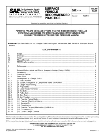
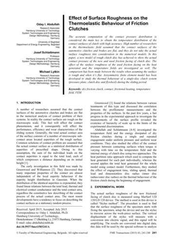
5.5.The degree of water saturation and concrete temperature may have a significant effect on theelectrical resistivity of concrete. A standardized conditioning procedure has been developed tominimize this effect.5.6.Factors that are known to affect resistivity as well as chloride ion penetration includewater/cement ratio, pozzolans, the presence of polymeric admixtures, air-void system, aggregatetype, and degree of consolidation.6.APPARATUS6.1.Surface Resistivity Apparatus—Apparatus needs to be able to supply a flat-topped trapezoidalwave at a frequency of about 13 Hz and a pk-pk level with a nominal voltage limit of 25V pk-pk.Use a Wenner probe capable of an adjustment of the probe tip spacing to 38.1 mm (1.5 in.).Figure 2—Surface Resistivity Apparatus with 4-Pin Wenner Probe ArraySpecimen holder to prevent specimen rotation while under test. (See Figure 3 for example.)Provided by : www.spic.ir-- , ,,,, , , ,,,,,, - - ,, ,, , ,, ---6.2.www.salmanco.comTS-3cT 358-4 2015 by the American Association of State Highway and Transportation Officials.Copyright American Association of State Highway and Transportation OfficialsAASHTO
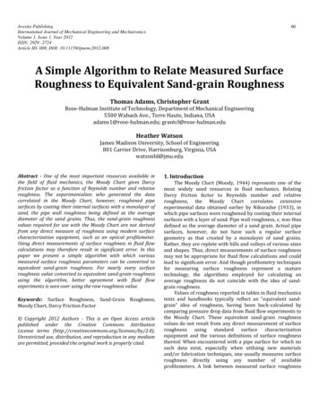
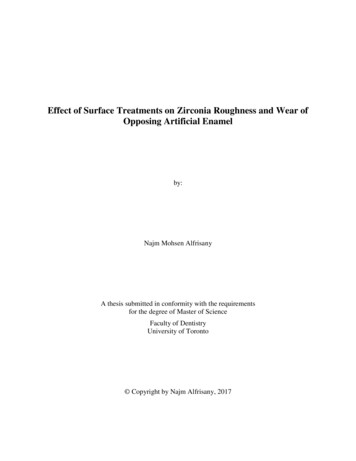
REAGENTS AND MATERIALS7.1.None required.8.TEST SAMPLES8.1.A set is composed of a minimum of three samples. Sample preparation and selection depends onthe purpose of the test. For evaluation of materials or their proportions, samples may be (a) coresfrom structures or from larger diameter cast cylinders, (b) 100-mm- (4-in.) diameter cast cylinders,or (c) 150-mm- (6-in.) diameter cast cylinders. Cylinders cast in the laboratory shall be preparedfollowing procedures in R 39. Unless specified otherwise, moist-cure test samples for 28 daysprior to testing (Notes 2 and 3).Note 2—This test method may be used with various test durations and curing regimens to meetagency guidelines or specifications. Moist-cure in a 100 percent relative humidity moist room isthe preferred curing method. Curing by immersion in lime solution produces results that aretypically lower by a factor of 10 percent. Care should be exercised when comparing resultsobtained from specimens subjected to differing conditions.Note 3—Accelerated Moist-Curing—Provide 7 days of moist-curing in accordance with R 39 forspecimens prepared in the laboratory or in accordance with the standard curing procedure of T 23for specimens prepared in the field. After 7 days of moist-curing, immerse the specimens for21 days in lime-saturated water at 38.0 2.0 C (100 3 F). The accelerated moist-curingprocedure has been found useful in providing an earlier indication of potential propertydevelopment with slower hydrating supplementary cementitious materials. Because the twodifferent curing methods may not provide the same results, the specifier of the test may require acorrelation between results for extended moist-cured and accelerated moist-cured specimens andestablish appropriate acceptance criteria when the accelerated moist-curing procedure is used orpermitted.Provided by : www.spic.ir7.www.salmanco.comTS-3cT 358-5 2015 by the American Association of State Highway and Transportation Officials.Copyright American Association of State Highway and Transportation OfficialsAASHTO-- , ,,,, , , ,,,,,, - - ,, ,, , ,, ---Figure 3—Specimen Holder
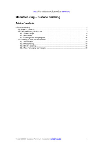
8.2.Transport the cores or field-cured cylinders to the laboratory in a moist condition in a sealedwatertight container. If samples must be shipped, they should be packed to be properly protectedfrom freezing and damage in transit or storage.8.3.Immediately after removing the sample from the mold, make four indelible marks on the topfinished circular face marking the 0-, 90-, 180-, and 270-degree points of the circumference.Randomly assign one of the marks as 0 degrees, and then counterclockwise assign the next markas 90 degrees, and so on. Extend the marks onto the longitudinal sides of each sample. On thelongitudinal sides of the sample, mark the center of the sample to use as a visual reference duringtesting. (See Figure 4 for example.)CONDITIONING9.1.In order to saturate concrete cylinders with water, they must remain in a 100 percent relativehumidity condition (moist room) from the moment of mold removal to the moment of the test.10.PROCEDURE10.1.During the test, the air temperature around the specimens shall be maintained in the range of 20 to25 C (68 to 77 F).10.2.Remove the first sample from the moist room or water tank and transfer the sample to the sampleholder with the 0-degree mark on top (Note 4). Immediately clean the surface with a saturatedsponge or towel. The surface should be saturated surface wet during testing.Note 4—One recommendation is to place the sample into a pan with about an inch of water androtate the sample during testing in order to prevent the sample from drying. If the sample begins todry, the resistivity readings drift higher, increase variability in the readings, and give erroneousresults. Frequently changing the water is also recommended (approximately every 5 samples).Keeping the sample surface wet during testing reduces testing variability.Provided by : www.spic.ir9.www.salmanco.comTS-3cT 358-6 2015 by the American Association of State Highway and Transportation Officials.Copyright American Association of State Highway and Transportation OfficialsAASHTO-- , ,,,, , , ,,,,,, - - ,, ,, , ,, ---Figure 4—Sample Marking
Place the Wenner array probe on the longitudinal side of the sample, making sure the longitudinalcenter mark is equidistant between the two inner probe pins. (See Figure 5.)-- , ,,,, , , ,,,,,, - - ,, ,, , ,, ---10.3.Figure 5—Wenner Array PlacementRecord the measurement from the display unit after the reading becomes stable. (See Table 2 inSection 11.)10.5.Rotate the sample from the 0- to the 90-degree mark, and repeat the steps in Sections 10.2 through10.4.10.6.Rotate the sample from the 90- to the 180-degree mark, and repeat the steps in Sections 10.2through 10.4.10.7.Rotate the sample from the 90- to the 270-degree mark, and repeat the steps in Sections 10.2through 10.4.10.8.Rotate the sample to the 0-degree mark and repeat the steps in Sections 10.3 through 10.7 for thesample in order to obtain a second set of readings at each degree mark. These will be used toobtain an average of two readings at each location.10.9.Repeat the steps in Sections 10.1 to 10.8 for the other samples in the set.Provided by : www.spic.ir10.4.www.salmanco.comTS-3cT 358-7 2015 by the American Association of State Highway and Transportation Officials.Copyright American Association of State Highway and Transportation OfficialsAASHTO
11.CALCULATION AND INTERPRETATION OF RESULTSTable 2—Sample Table for Recording the Surface Resistivity ReadingsSurface Resistivity (SR) Readings, kΩ-cmSample0 90 180 270 0 90 180 270 AverageABCProvided by : www.spic.ir11.1.Calculate the average resistivity and the percent relative standard deviation (%RSD) for eachsample in the set. If the %RSD is above 7.5 percent, immerse the sample in a water bath (20 to25 C (68 to 77 F)) for 2 h, and then repeat the test. If the %RSD on the second set is below 7.5percent, use the last set of readings to compute the average. If the %RSD is greater than 7.5percent, then average all 16 readings.11.2.Calculate the average
TS-3c T 358-2 AASHTO of the concrete. The resistivity, in kilohms-centimeters (kΩ-cm), has been found to be related to the resistance of the specimen to chloride ion penetration. 4. SIGNIFICANCE AND USE 4.1. This test method covers the laboratory evaluation of the electrical resistivity of concrete samplesFile Size: 1MBPage Count: 10