Transcription
Using Term Rewriting Systems to Design and VerifyProcessorsComputation Structures Group Memo 419November 1998Arvind and Xiaowei Shenarvind, xwshen@lcs.mit.eduTo appear in IEEE Micro Special Issue on "Modeling and Validation of Microprocessors", May/June 1999.This paper describes research done at the Laboratory for Computer Science of theMassachusetts Institute of Technology. Funding for this work is provided in partby the Advanced Research Projects Agency of the Department of Defense underthe O ce of Naval Research contract N00014-92-J-1310 and Ft Huachuca contractDABT63-95-C-0150.
Using Term Rewriting Systems to Design and Verify ProcessorsArvind and Xiaowei ShenLaboratory for Computer ScienceMassachusetts Institute of Technologyarvind, xwshen@lcs.mit.eduAbstractWe present a novel use of Term Rewriting Systems (TRS's) to describe micro-architectures.The state of a system is represented as a TRS term while the state transitions are representedas TRS rules. TRS descriptions are amenable to both veri cation and synthesis. We illustratethe use of TRS's by giving the operational semantics of a simple RISC instruction set. Wethen present another TRS that implements the same instruction set on a micro-architecturewhich permits register renaming and speculative execution. The correctness of the speculativeimplementation is discussed in terms of the ability of the two TRS's to simulate each other. Ourmethod facilitates understanding of important micro-architectural di erences without delvinginto low-level implementation details.1 IntroductionTerm Rewriting Systems (TRS's) o er a convenient way to describe parallel and asynchronoussystems, and can be used to prove the correctness of an implementation with respect to a speci cation. TRS descriptions, augmented with proper information about the building blocks, also holdthe promise of high-level synthesis. High-level architectural descriptions, which are both automatically synthesizable and veri able, open up the possibility of architectural exploration at a fractionof the time and cost than what is feasible using current commercial tools.Formal veri cation of microprocessors has gained considerable attention in recent years [2, 3,7, 11]. Other formal techniques, such as Lamport's TLA and Lynch's I/O automata, can also beused to model microprocessors. While all these techniques have something in common with TRS's,we nd the use of TRS's more intuitive in both architecture descriptions and correctness proofs.TRS's can be used to describe both deterministic and non-deterministic computations. Althoughthey have been used extensively in programming language research to give operational semantics,their use in architectural descriptions is novel.In this paper, we will use TRS's to describe a speculative processor capable of register renamingand out-of-order execution. The lack of space does not permit us to discuss a synthesis procedurefrom TRS's or to give su cient details that are needed to make automatic synthesis feasible.Nevertheless, we will show that our speculative processor produces the same set of behaviors asa simple non-pipelined implementation. Though the reader is the ultimate judge, we believe thatour descriptions of micro-architectures are more precise than what one may nd in a moderntextbook [4]. It is the clarity of these descriptions that lets us study the impact of features such aswrite bu ers or caches, especially in multiprocessor systems [10, 9]. In fact, part of the motivationfor this work came from one of the author's experience in teaching computer architectures.1
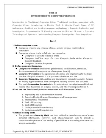
2 Term Rewriting SystemsA term rewriting system is de ned as a tuple (S, R, S0 ), where S is a set of terms, R is a set ofrewriting rules, and S0 is a set of initial terms (S0 S). In the architectural context, the termsand rules of a TRS represent states and state transitions, respectively. The general structure ofrewriting rules is as follows:s1 if p (s1)! s2where s1 and s2 are terms, and p is a predicate.A rule can be used to rewrite a term if the left-hand-side pattern of the rule matches the termor one of its subterms, and the corresponding predicate is true. The new term is generated inaccordance with the right-hand-side of the rule. If several rules are applicable, then any one ofthem can be applied. If no rule is applicable, then the term cannot be rewritten any further. Inpractice, we often use abstract data types such as arrays and FIFO queues to make the descriptionsmore readable. More information about TRS's can be found elsewhere [1, 6].A small but fascinating example of term rewriting is provided by the SK combinatorysystem, which has only two rules, and a simple grammar for generating terms. Thesetwo rules are su cient to describe any computable function!TERM K [] S [] TERM.TERMK-rule:S-rule:(K.x).y((S.x).y).z! x! (x.z).(y.z)The interested reader may want to verify that, for any subterm x, the term ((S.K).K).xcan be rewritten to (K.x).(K.x) by applying the S-rule. This term can be rewrittenfurther to x by applying the K-rule. Thus, if one reads the .' as function applicationthen the term ((S.K).K) behaves as the identity function.Notice the S-rule rearranges .' and duplicates the term represented by x on the righthand-side. In architectures where terms represent states, rules must be restricted so thatterms are not restructured or duplicated.3 AX: A Minimalist RISC Instruction SetWe will use AX, a minimalist RISC instruction set, to illustrate all the examples in this paper.The TRS description of a simple AX architecture also provides a good introductory example to theTRS notation.In the AX instruction set (see Figure 1), all arithmetic operations are performed on registersand only the Load and Store instructions are allowed to access memory. The grammar uses []' asa meta notation to separate disjuncts. Throughout the paper r' represents a register name, v'a value, a' a data memory address and ia' an instruction memory address. An identi er maybe quali ed with a subscript. We do not specify the number of registers, the number of bits in aregister or value, or the exact bit-format of each instruction. Such details are not necessary for ahigh-level description of a micro-architecture but are needed for synthesis.2
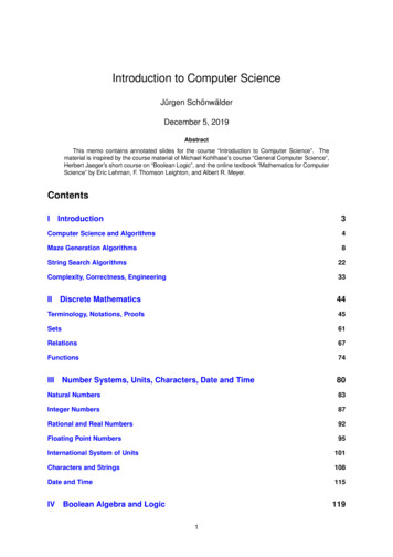
INST [][][][][]r: Loadc(v)r: Loadpcr: Op(r1 ,r2 )Jz(r1 ,r2 )r: Load(r1 )Store(r1 ,r2 )Load-constant InstructionLoad-program-counter InstructionArithmetic-operation InstructionBranch InstructionLoad InstructionStore InstructionFigure 1: AX Instruction SetTo avoid unnecessary complications, we assume that the instruction address space is disjointfrom the data address space, so that self-modifying code is forbidden. AX is powerful enough tolet us express all computations as location independent, non-self-modifying programs.Semantically, AX instructions are executed strictly according to the program order: the programcounter is incremented by one each time an instruction is executed except for the Jz instruction,where the program counter is set appropriately according to the branch condition. The informalmeaning of the instructions is as follows:The load-constant instruction r: Loadc(v) puts constant v into register r. The load-programcounter instruction r: Loadpc puts the content of the program counter into register r. Thearithmetic-operation instruction r: Op(r1 ,r2 ) performs the arithmetic operation speci ed by Opon the operands speci ed by registers r1 and r2 , and puts the result into register r. The branchinstruction Jz(r1 ,r2 ) sets the program counter to the target instruction address speci ed by registerr2 if register r1 contains value zero; otherwise the program counter is simply increased by one. Theload instruction r: Load(r1 ) reads the memory cell speci ed by register r1 , and puts the data intoregister r. The store instruction Store(r1 ,r2 ) writes the content of register r2 into the memory cellspeci ed by register r1 .We de ne the operational semantics of AX instructions using the PB model, a single-cycle, nonpipelined, in-order execution processor. The datapath for such a system is shown in Figure 2. Theprocessor consists of a program counter (pc), a register le (rf), and an instruction memory (im).The program counter holds the address of the instruction to be executed. The processor togetherwith the data memory (dm) constitutes the whole system, which can be represented as the TRSterm Sys(Proc(pc, rf, im), dm). The semantics of each instruction can be given as a rewriting rulewhich speci es how the state is modi ed after each instruction is executed.It is important to realize that pc, rf, im and dm can be grouped syntactically in any convenientway. Grouping them as Sys(Proc(pc, rf, im), dm) instead of Sys(pc, rf, im, dm) provides a degreeof modularity in describing the rules that do not refer to dm. Abstract data types can also enhancemodularity. For example, rf, im and dm are all represented using arrays on which only two operations, selection and update, can be performed. Thus, rf[r] refers to the content of register r, andrf[r: v] represents the register le after register r has been updated with value v. Similarly, dm[a]refers to the content of memory location a, and dm[a: v] represents the memory with location aupdated with value v.We use the following notational conventions in the rewriting rules: all the special symbols suchas : ', and all the identi ers that start with capital letters are treated as constants in patternmatching. We use -' to represent the wild-card term that can match any term. Notation Op(v1 ,v2 )represents the result of operation Op with operands v1 and v2 .3
DataMemdm 1pcInst.MemReg.FileimrfALUSys(Proc(pc, rf, im), dm)Figure 2: The PB Model: A Single-Cycle In-Order ProcessorLoadc RuleProc(ia, rf, im) if im[ia] r: Loadc(v)! Proc(ia 1, rf[r: v], im)Loadpc RuleProc(ia, rf, im) if im[ia] r: Loadpc! Proc(ia 1, rf[r: ia], im)Op RuleProc(ia, rf, im) if im[ia] r: Op(r1 ,r2 )! Proc(ia 1, rf[r: v], im) where v Op(rf[r1 ],rf[r2 ])Jz-Jump RuleProc(ia, rf, im) if im[ia] Jz(r1 ,r2 ) and rf[r1 ] 0! Proc(rf[r2 ], rf, im)Jz-NoJump RuleProc(ia, rf, im) if im[ia] Jz(r1 ,r2 ) and rf[r1 ] 6 0! Proc(ia 1, rf, im)Load RuleSys(Proc(ia, rf, im), dm) if im[ia] r: Load(r1)! Sys(Proc(ia 1, rf[r: dm[a]], im), dm) where a rf[r1 ]Store RuleSys(Proc(ia, rf, im), dm) if im[ia] Store(r1 ,r2 )! Sys(Proc(ia 1, rf, im), dm[a: rf[r2 ]]) where a rf[r1 ]Since the pattern Proc(ia, rf, im) will match any processor term, the real discriminant is theinstruction at address ia. In the case of a branch instruction, further discrimination is made basedon the value of the condition register.It is important to understand the atomic nature of these rules. Once a rule is applied, the statespeci ed by its right-hand-side must be reached before any other rule can be applied. For example,on an Op instruction, both operands must be fetched and the result computed and stored in theregister le in one atomic action. Furthermore, the program counter must be updated during thisatomic action as well. This is why these rules describe a single-cycle, non-pipelined implementationof AX.To save space, we may use a table to describe the rules informally. For example, Figure 3summarizes the PB rules given above. It is our hope that, given proper context, the reader will beable to deduce the precise TRS rules from a tabular description.4
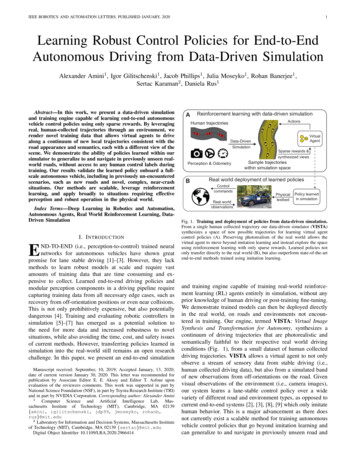
Rule Name Instruction at ia Next pcLoadcLoadpcOpJzr: Loadc(v)r: Loadpcr: Op(r1 ,r2 )Jz(r1 ,r2 )LoadStorer: Load(r1 )Store(r1 ,r2 )ia 1ia 1ia 1ia 1 (if rf[r1 ] 6 0)rf[r2 ] (if rf[r1 ] 0)ia 1ia 1Next rfNext dmrf[r: dm[rf[r1 ]]]rfdmdm[rf[r1 ]: rf[r2 ]]rf[r: v]rf[r: ia]rf[r: Op(rf[r1 ],rf[r2 ])]rfdmdmdmdmFigure 3: Operational Semantics of AX (Current State: Sys(Proc(ia, rf, im), dm))4 Register Renaming and Speculative ExecutionThere are many possible micro-architectures that can implement the AX instruction set. Forexample, in a simple pipelined architecture, instructions are fetched, executed and retired in order,and there can be as many as 4 or 5 partially executed instructions in the processor. Storage inthe form of pipeline bu ers is provided to hold these partially executed instructions. In moresophisticated pipelined architectures, there are multiple functional units, which may be specializedfor integer or oating-point calculations. In such architectures, even if instructions are issued inorder, they may complete out of order because of varying latencies of functional units. To preservecorrectness, a new instruction is not issued when there is another instruction in the pipeline thatmay update any register to be read or written by the new instruction. Seymore Cray's CDC 6600,which is one of the earliest examples of such an architecture, used a scoreboard to dispatch andtrack partially executed instructions in the processor. In Cray-style scoreboard design, the numberof instructions in the pipeline is limited by the number of registers in the instructions set.The technique of register renaming was invented by Tomasulo at IBM in mid sixties to overcomethis limitation on pipelining. Tomasulo assigned a renaming tag to each instruction as it wasdecoded. The following instructions used this tag to refer to the value produced by this instruction.A renaming tag became free, i.e., could be used again, once the instruction was completed. Themicro-architecture maintained the association between the register name, the tag and the associatedvalue (whenever the value became available). This innovative idea was embodied in IBM 360/91 inlate sixties but went out of favor until late eighties for several reasons. For example, the performancegains were not considered commensurate with the complexity of the implementations. Registerrenaming is common place today and present in all the high-end microprocessors (PentiumPro,PowerPC 604, MIPS R10000 and later models in these product lines).An important state element in a micro-architecture with register renaming is a reorder bu er(ROB), which holds instructions that have been decoded but have not completed their execution(see Figure 4). Conceptually, ROB divides the processor into two asynchronous parts: the rst partfetches an instruction and, after decoding and renaming registers, dumps it into the next availableslot in the ROB. The ROB slot index serves the purpose of the renaming tag, and the instructionsin the ROB always contain tags or values instead of register names. An instruction in the ROBcan be executed if all its operands are available. The second part takes any enabled instructionout of the ROB and dispatches it to an appropriate functional unit, including the memory system.This mechanism is very similar to the execution mechanism in data ow architectures. Such anarchitecture may execute instructions out of order, especially if functional units have di erentlatencies or there are data dependencies between instructions.In addition to register renaming, most contemporary microprocessors also permit speculative5
Kill / Update eorder BufferrobMemmpbALUsCommitrfSys(Proc(pc, rf, rob, btb, im), pmb, mpb)Figure 4: The PS Model: A Processor with Register Renaming and Speculative Executionexecution of instructions. The speculative mechanisms predict the address of the next instruction tobe issued based on the past behavior of the program. (Several researchers have recently suggestedmechanisms to speculate on memory values as well but none of these have been implemented so far;we do not consider such mechanisms in this paper). The address of the speculative instruction isdetermined by consulting a table known as the branch target bu er (BTB), which can be indexedby the current content of the program counter. If the prediction turns out to be wrong, thespeculative instruction and all the instructions issued thereafter are abandoned and their e ect onthe processor state nulli ed. The BTB is updated according to some prediction scheme after eachbranch resolution.The correctness of the speculative processor is not contingent upon how the BTB is maintained,as long as the program counter can be set to the correct value after a misprediction. However, different prediction schemes can give rise to very di erent misprediction rates and thus have profoundin uence on the performance. Generally, it is assumed that the BTB produces the correct nextinstruction address for all non-branch instructions. We will not discuss the BTB any further because the branch prediction strategy is completely orthogonal to the mechanisms for speculativeexecution.Any processor that permits speculative execution has to make sure that a speculative instructioneither does not modify the programmer visible state until it can be \committed", or save enoughof the processor state so that the correct state can be restored in case the speculation turns outto be wrong. Most implementations use a mixture of these two ideas: speculative instructions donot modify the register le or memory until it can be determined that the prediction is correct,but are allowed to update the program counter. Both the current and the speculated instructionaddress are recorded so that the correctness of speculation can be determined later, and the correctprogram counter can be restored in case of wrong prediction. Typically, all the temporary state ismaintained in the ROB itself.5 PS: A Speculative ProcessorWe now present the rules for a simpli ed micro-architecture that does register renaming and speculative execution. The simpli cation is achieved by not showing all the pipelining and not giving thedetails of some hardware operations. The memory system is modeled as operating asynchronouslywith respect to the processor. Thus, a memory instruction in the ROB is dispatched to the memorysystem via an ordered processor-to-memory bu er (pmb); the memory provides its responses via a6
memory-to-processor bu er (mpb). Exactly how the memory system is organized is not discussed.However, memory system details can be added in a modular fashion without changing the processordescription presented here [10, 9].We need to add two new components, rob and btb, to the processor state. Reorder bu er robis a complex device to model because di erent types of operations need to be performed on it. Itcan be thought of as a FIFO queue which is initially empty ( ). We use the constructor ', whichis associative but not commutative, to represent this aspect of rob. It can also be considered asan array of instruction templates where array index serves the purpose of a renaming tag. It iswell known that a FIFO queue can be implemented as a circular bu er using two pointers into anarray. We will hide these implementation details of rob and assume that the next available tag canbe obtained.An instruction template in rob contains the instruction address, opcode, operands and someextra information needed to complete the instruction. For instructions that need to update aregister, the Wr(r) eld records the destination register r. For branch instructions, the Sp(pia)eld holds the speculated instruction address pia which will be used to determine the correctnessof the prediction. Each memory access instruction maintains an extra ag to indicate whetherthe instruction is waiting to be dispatched (U), or has been dispatched to the memory (D). Thememory system returns a value for a load and an acknowledgment (Ack) for a store. We have takensome syntactic liberties in expressing various types of instruction templates below:ROB Entry Itb(ia,t: v,Wr(r))[][][][]Itb(ia,t: Op(tv1 ,tv2 ),Wr(r))Itb(ia,Jz(tv1 ,tv2 ),Sp(pia))Itb(ia,t: Load(tv1 ,mf),Wr(r))Itb(ia,t: Store(tv1 ,tv2 ,mf))where tv stands for either a tag or a value, and the memory ag mf is either U or D. The tag usedin the Store instruction template is intended to provide some exibility in coordinating with thememory system, and does not imply updating of any register.5.1 Instruction Fetch RulesEach time an instruction is issued, the program counter is set to the address of the next instructionto be issued. For non-branch instructions, the program counter is simply incremented by one.Speculative execution happens when a Jz instruction is issued: the program counter is then set tothe instruction address obtained by consulting the btb entry corresponding to the address of the Jzinstruction.When an instruction is issued, an instruction template for the issued instruction is allocated inthe rob. If the instruction is to modify a register, an unused renaming tag (typically the index of theslot in the rob) is used to rename the destination register and the destination register is recordedin the Wr eld. The tag or value of each operand register is found by searching the rob from theyoungest bu er (rightmost) to the oldest bu er (leftmost) until an instruction template containingthe referenced register is found. If no such bu er exists in the rob, then the most up-to-date valueresides in the register le. The following lookup procedure captures this idea:lookup(r, rf, rob) rf[r] if Wr(r) 2 roblookup(r, rf, rob1 Itb(ia,t: -,Wr(r)) rob2 ) tif Wr(r) 2 rob27
Rule Name Instruction at ia New Template in adFetch-Storer: Loadc(v)r: Loadpcr: Op(r1 ,r2 )Jz(r1 ,r2 )r: Load(r1 )Store(r1 ,r2 )Itb(ia,t: v,Wr(r))Itb(ia,t: ia,Wr(r))Itb(ia,t: Op(tv1 ,tv2 ),Wr(r))Itb(ia,Jz(tv1 ,tv2 ),Sp(btb[ia]))Itb(ia,t: Load(tv1 ,U),Wr(r))Itb(ia,t: Store(tv1 ,tv2 ,U))Next pcia 1ia 1ia 1btb[ia]ia 1ia 1Figure 5: PS Instruction Fetch Rules (Current state: Proc(ia, rf, rob, btb, im))It is beyond the scope of this paper to give a hardware implementation of this procedure but itis certainly possible to do so using TRS's. Any implementation that can look up values in the robusing a combinational circuit would su ce.For example, the fetch rule for an Op instruction simply puts the instruction after registerrenaming at the end of the rob as follows:Fetch-Op RuleProc(ia, rf, rob, btb, im) if im[ia] r: Op(r1 ,r2 )! Proc(ia 1, rf, rob Itb(ia,t: Op(tv1 ,tv2 ),Wr(r)), btb, im)where t represents an unused tag; tv1 and tv2 represent the tag or value corresponding to theoperand registers r1 and r2 , respectively, i.e., tv1 lookup(r1 , rf, rob), tv2 lookup(r2 , rf, rob).The instruction fetch rules are summarized Figure 5. In any implementation, there are a nitenumber of rob entries, and the instruction fetch has to be stalled if rob is full. This availabilitychecking can be easily modeled, and we leave it as a simple exercise for the interested reader. Itshould be noted that a fast implementation of the lookup procedure in hardware is quite di cult.Often a renaming table that keeps the association between a register name and its current tag ismaintained separately.5.2 Arithmetic Operation and Value Propagation RulesThe arithmetic operation rule states that an arithmetic operation in the rob can be performed ifboth operands are available. It assigns the result to the corresponding tag. Note that the instructioncan be in any position in the rob.Op RuleProc(ia, rf, rob1 Itb(ia1 ,t: Op(v1 ,v2 ),Wr(r)) rob2 , btb, im)! Proc(ia, rf, rob1 Itb(ia1 ,t: v,Wr(r)) rob2 , btb, im) where v Op(v1 ,v2 )There are two value propagation rules, the forward rule and the commit rule. The forwardrule sends the value of a tag to other instruction templates, while the commit rule writes the valueproduced by the oldest instruction in the rob to the destination register and retires the correspondingrenaming tag. Notation rob2 [v/t] means that one or more appearances of tag t in rob2 are replacedby value v.Value-Forward RuleProc(ia, rf, rob1 Itb(ia1 ,t: v,Wr(r)) rob2 , btb, im) if t 2 rob2! Proc(ia, rf, rob1 Itb(ia1 ,t: v,Wr(r)) rob2 [v/t], btb, im)Value-Commit RuleProc(ia, rf, Itb(ia1 ,t: v,Wr(r)) rob, btb, im) if t 2 rob! Proc(ia, rf[r: v], rob, btb, im)8
Rule Namerob rob1 Itb(ia1,Jz(0,nia),Sp(pia)) rob2 Next rob Next pcpia niarob1 rob2 iapia 6 niarob1niaRule NameNext rob Next pcrob1 rob2 iaJump-CorrectSpecJump-WrongSpecrob rob1 Itb(ia1,Jz(v,-),Sp(pia)) rob2NoJump-CorrectSpec v 6 0, pia ia1 1NoJump-WrongSpec v 6 0, pia 6 ia1 1rob1ia1 1Figure 6: PS Branch Completion Rules (Current state: Proc(ia, rf, rob, btb, im). btb update is notshown)It is worth noting that the rob pattern in the commit rule dictates that the register le canonly be modi ed by the oldest instruction after it has forwarded the value to all the bu ers inthe rob that reference its tag. Restricting the register update to just the oldest instruction in therob eliminates output (write-after-write) hazards, and protects the register le from being pollutedby incorrect speculative instructions. It also provides a way to support precise interrupts. Thecommit rule is needed primarily to free up resources and to allow the reuse of the tag by thefollowing instructions.5.3 Branch Completion RulesThe branch completion rules determine if the branch prediction was correct by comparing thespeculated instruction address and the resolved branch target instruction address. If they donot match (indicating that the speculation was wrong), all instructions issued after the branchinstruction are aborted, and the program counter is set to the new branch target instruction. Thebranch target bu er btb is updated according to some prediction algorithm. The branch resolutioncases are summarized in Figure 6.The reader may want to ponder over the fact that the branch rules allow branches to be resolvedin any order. The branch resolution mechanism becomes slightly complicated, if certain instructionsneeded to be killed are waiting for responses from the memory system or some functional units.In such a situation, killing may have to be postponed until no instruction in rob2 is waiting for aresponse. (This is not possible for the rules that we have presented).5.4 Memory Access RulesMemory requests are sent to the memory system strictly in order and only when there is nounresolved branch instruction in front of it. This dispatch rules ip the U bit to D, and enqueuethe memory request into the pmb. The memory system can respond to the requests in any orderand the response is used to update the appropriate entry in the rob. The ;' is used to represent anordered queue, and the j' an unordered queue (i.e., it is both commutative and associative). Thememory access rules are given in Figure 7.We do not present the rules for how the memory system handles memory requests from thepmb. The table in Figure 8 shows a simple interface between the processor and the memorythat ensures memory accesses are processed in order by the external memory system to guaranteesequential consistency in multiprocessor systems. More aggressive implementations of memoryaccess operations are possible than the ones presented here, but they lead to various relaxed memorymodels in multiprocessor systems. A discussion of such optimizations is beyond the scope of thispaper.9
Rule NameitbpmbRule NameLoad-RetireStore-RetireitbNext itbNext pmbItb(ia1,t: Store(a,v,D))pmb;ht,Store(a,v)iNext itbNext mpbItb(ia1,t: Load(a,D),Wr(r)) pmb;ht,Load(a)iLoad-Dispatch Itb(ia1 ,t: Load(a,U),Wr(r)) pmbU, Jz 2 rob1Store-Dispatch Itb(ia1 ,t: Store(a,v,U))pmbU, Jz 2 rob1mpbItb(ia1 ,t: Load(a,D),Wr(r)) ht,vijmpbItb(ia1,t: v,Wr(r))Itb(ia1 ,t: Store(a,v,D))ht,Ackijmpb (deleted)mpbmpbFigure 7: PS Memory Access Rules (Current state: Sys(Proc(ia, rf, rob1 itb rob2 , btb, im), pmb,mpb))dm pmbmpb Next dm Next pmb Next mpbdm ht,Load(a)i;pmbmpb dmpmbmpbjht,dm[a]idm ht,Store(a,v)i;pmb mpb dm[a: v] pmbmpbjht,AckiFigure 8: Processor-Memory Interface Speci cation6 Correctness of the PS ModelOne way to prove that the speculative processor is a correct implementation of the AX instructionset is to show that PB and PS can simulate each other in regards to some observable property. Anatural observation function is the one that can extract all the programmer visible state, includingthe program counter, the register le and the memory from the system. One can think of anobservation function in terms of a print instruction that prints a part or the whole of the programmervisible state. If model A can simulate model B , then for any program, model A should be able toprint whatever model B prints during the execution.The programmer visible state of PB is obvious { it is the whole term. The PB model doesnot have any hidden state. It is a bit tricky to extract the corresponding values of pc, rf and dmfrom the PS model because of the partially or speculatively executed instructions. However, if weconsider only those PS states where the rob, pmb and mpb are empty then it is straightforward tond the corresponding PB state. We will call such states of PS as the drained states.It is easy to show that PS can simulate each rule of PB . Given a PB term s1 , a PS term t1 iscreated such that it has the same values of pc, rf, im and dm, and its rob, pmb and mpb are allempty. Now, if s1 can be rewritten to s2 according to some PB rule then we can apply a sequenceof PS rules to t1 to obtain t2 such that t2 is in a drained state and has the same programmer visiblestate as s2 . In this manner, PS can simulate each move of PB .The simulation in the other direction is tricky because we need to nd a PB term correspondingto each term (not just the terms in the drained state) of PS . We somehow need to extract theprogrammer visible state from any PS term. There are several ways in which a PS term can bedriven to a drained state using the PS rules, and each way may lead to a di erent drained state.We illustrate this via an example.Consider the snapshot shown in Figure 9(a) (we have not shown pmb and mpb and let us assumeboth are empty). There are at least two ways to drive this term into a drained state. One way isto stop fetching instructions and complete all the partially executed instructions. This process c
The load-program-coun ter instruction r: Loadp c puts the con ten t of program in to register. The arithmetic-op eration instruction r: Op(1, 2) p erforms the arithmetic op eration sp eci ed b y Op on the op erands sp eci ed b y registers r 1 and 2, puts result in to register. The branc h instruction Jz(r 1, 2) sets the program coun ter to the .