Transcription
High-speed Serial InterfaceLect. 6 – TX Driver and Equalizer1High-Speed Circuits and Systems Lab., Yonsei University2013-1
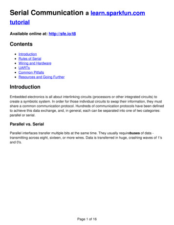
Block diagram Where are we izerClockRecoveryPLLTx2SamplerRxHigh-Speed Circuits and Systems Lab., Yonsei University2013-1
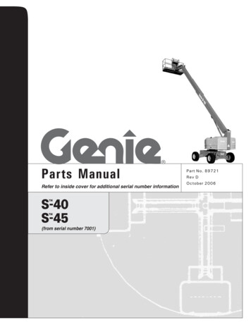
Classic output driver An inverter can be used as voltage-mode outputdriverRRTTL output buffer3CMOS output bufferHigh-Speed Circuits and Systems Lab., Yonsei University2013-1
Classic output driver It is difficult to use inverter-style output driver inhigh-speed applications– Full-swing logic is speed-limited because of slow switching timeof inverter-style driver– Impedance matching is not easy Transistors have variable output resistances during output voltagetransients4High-Speed Circuits and Systems Lab., Yonsei University2013-1
Single-ended signaling Signal is transferred via single channelSimple but Threshold should be generated in RX side.– Logic levels in TX may not be same as in RX side Supply and ground levels are different for RX and RX sides Poor noise immunity– Noises are added while signals travel through channel50-Ω Channel5High-Speed Circuits and Systems Lab., Yonsei UniversityThresholdgeneratedin RX2013-1
Differential signaling Differential signals are transferred via twoadjacent channels– Each signal has opposite logic level– Ex) twisted pair, differential PCB linesPositive channelNegative channelDifferential 100Ω6High-Speed Circuits and Systems Lab., Yonsei University2013-1
Differential signaling Larger signal swing and self-reference– Signal (positive signal – negative signal) Decision margin enhanced– threshold (positive signal negative signal)/2 Common-mode noise rejection– Noise usually affects both positive and negative channels– Subtraction rejects common-mode noiseCommon-modenoisePositive channelNegative channelDifferential 100Ω7High-Speed Circuits and Systems Lab., Yonsei University2013-1
Current-mode driver Reduced switching time– Current-steering: Switching current path while source current iskept constant.– Switching time is reduced since current source is not turned-off DisadvantageI – Differential signaling is required.– Static current causesstatic power consumption Usually larger power consumptionthan voltage-mode8High-Speed Circuits and Systems Lab., Yonsei UniversityI-Ibias2013-1
50-Ω termination Why 50Ω?– Historical issue In early microwave systems, it was known that– 33Ω shows best performance in power transfer– 75Ω shows best performance in signaling– For convenience, 50 Ω was selected instead of medium value, 54 Ω Nowadays, almost all high-speed instruments are 50Ω-based Significant for high-speed serial interface– In CATV systems, 75-Ω termination is still used9High-Speed Circuits and Systems Lab., Yonsei University2013-1
50-Ω termination Tx-side termination topology– Voltage-mode driver has small output impedance Series termination50-Ω Channel50Ω50ΩVoltage-modeDriver(Ro 0Ω)– Current-mode driver has large output impedance Parallel termination50-Ω ChannelCurrent-modeDriver(Ro Ω)1050ΩHigh-Speed Circuits and Systems Lab., Yonsei University50Ω2013-1
DC- and AC-coupling AC coupling with a series capacitor– Both TX and RX are possible– Common-mode voltage can be separately controlled in both side– Coupling capacitor can causes low-frequency loss Capacitance 100nF is generally used.50-Ω Channel50Ω50ΩVoltage-modeDriver50-Ω ChannelCurrent-modeDriver1150ΩHigh-Speed Circuits and Systems Lab., Yonsei University50Ω2013-1
DC- and AC-coupling AC coupling cannot be used if consecutiveidentical bits are transmitted 8B/10B coding for many standards50-Ω Channel50Ω50ΩVoltage-modeDriver50-Ω ChannelCurrent-modeDriver1250ΩHigh-Speed Circuits and Systems Lab., Yonsei University50Ω2013-1
Push-pull driver 2 current sources13IN Positive channel100Ω– Current path switching– Upper and lower pairs– Same rising and falling timeINfor each differential signal– Upper PMOS pair can bereplaced by NMOS pair toenhance switching time– Head room problem in lowINvoltage technologies– Used in Low-Voltage DifferentialSignals (LVDS) standard– TX termination?Negative channelIN IbiasHigh-Speed Circuits and Systems Lab., Yonsei University2013-1
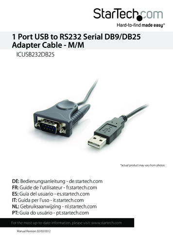
CML (Current-Mode Logic) driver Loaded by 50ohm resistorVDD50Ω50ΩPositive channelNegative channelIN IN-IbiasVSS14High-Speed Circuits and Systems Lab., Yonsei University2013-1100Ω– Current steering– Both side are terminated by 50Ω– Output voltage can beboth DC, AC-coupled– Used in most high-performanceserial link
TX equalization Channel causes ISI on received signal.– High-frequency loss in channel eye-diagram closedTxDriver15ChannelHigh-Speed Circuits and Systems Lab., Yonsei UniversityRxSampler2013-1
TX equalization TX driver can be also channel equalizer– TX driver can enhance high-frequency components beforetraveling through channel.TxDriver16ChannelHigh-Speed Circuits and Systems Lab., Yonsei UniversityRxSampler2013-1
How to reject ISI? FIR filtering– Forcing cursors to 0 can be implemented by FIR filtering.– ISI can be removed since we know input data in TX-side– Tx-side FIR filtering can include pre-cursorSubtractpre-cursor tract1st post-cursor 2nd post-cursorMain bitPeriodDelayHigh-Speed Circuits and Systems Lab., Yonsei University2013-1
Feedforward vs Feedback DFEDecisionInputData(Digital)Channel 8SamplerEqualization1-bitPeriodDelayHigh-Speed Circuits and Systems Lab., Yonsei University2013-1
Pre-/De-Emphasis– Tx FIR is often called Pre-/De-Emphasis De-emphasis: to reduce low-frequency components Pre-emphasis: to enhance high-frequency components– High-frequency component is transition bitsNormalWaveformNominalswingNominal nalswingHigh-Speed Circuits and Systems Lab., Yonsei University2013-1
Circuit implementation Current-mode drivers can be easily used for pre/de-emphasis– It is very easy to modify drivers into current-mode adderincluding controllable gainVDD50ΩPositive channelNegative channelD 0 D 0-D 1-D 1 Main cursorC0100Ω50Ω1st post-cursorC1VSS20High-Speed Circuits and Systems Lab., Yonsei University2013-1
Circuit implementation Simultaneous implementation of pre-/de-emphasis– D1 D0 Vout,diff /-50 x (C0-C1) De-emphasis– D1 D0 Vout,diff /-50 x (C0 C1) Pre-emphasis– Level difference is defined as sum and subtractVDD50ΩPositive channelNegative channelD 0 D 0-D 1-100Ω50ΩD 1 50x(C0 C1)50x(C0-C1)Main cursorC01st post-cursorC1VSS21High-Speed Circuits and Systems Lab., Yonsei University-50x(C0-C1)-50x(C0 C1)2013-1
Tx- vs. Rx- equalization Tx equalization– Consumes large power– Enlarged output signal improves SNR at Rx side– Easy implementation Rx equalization– Relatively low power consumption– More complex implementation (especially DFE)– For best performance, LE and DFE combination22High-Speed Circuits and Systems Lab., Yonsei University2013-1
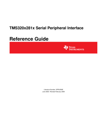
Design example“4-Channel 3.2/6.4-Gbps Dual-rate Transmitter”김두호, 최우영대한전자공학회 논문지 20104ch transmitter with 1-tap pre-emphasisDual-rate (3.2/ 6.4 Gbps)130nm CMOS technology / COB package600mW dissipation @1.2V power supply23High-Speed Circuits and Systems Lab., Yonsei University2013-1
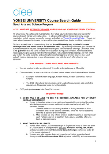
Design example 4-channel transmitter sharing a clock generator– 2:1 serializer function is included in pre-emphasis circuit– Displayport application24High-Speed Circuits and Systems Lab., Yonsei University2013-1
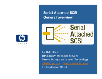
Design example Clock generator performance– PLL jitter is main performance metric of transmitter evaluation.3.2Gb/s256.4Gb/sHigh-Speed Circuits and Systems Lab., Yonsei University2013-1
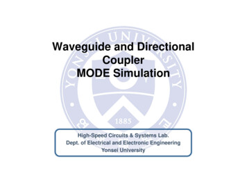
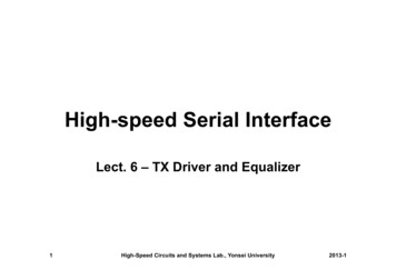
Design example De-emphasis waveform3.2Gb/s26Vswing 600mVdiff / De-emphasis 1/3Vswing 600mVdiff / De-emphasis 1/2Vswing 600mVdiff / De-emphasis 2/3Vswing 600mVdiff / De-emphasis 1High-Speed Circuits and Systems Lab., Yonsei University2013-1
Design example De-emphasis waveform6.4Gb/s27Vswing 600mVdiff / De-emphasis 1/3Vswing 600mVdiff / De-emphasis 1/2Vswing 600mVdiff / De-emphasis 2/3Vswing 600mVdiff / De-emphasis 1High-Speed Circuits and Systems Lab., Yonsei University2013-1
5 High-Speed Circuits and Systems Lab., Yonsei University 2013-1 50-ΩChannel Threshold generated in RX. Differential signaling Differential signals are transferred via two adjacent channels - Each signal has opposite logic level - Ex) twisted pair, differential PCB lines