Transcription
R evi e w A r tic leUltrasound as a diagnostic boon in Dentistry A ReviewShubham Sharma,1Deepali Rasila,2Mohit Singh,3Mansha Mohan4BDS, 2BDS, 3Post Graduate Student, Department of Prosthdontics and Implantology, D J College ofDental Sciences & Research, Modinagar (Uttar Pradesh) India, 4Post Graduate Student, Departmentof Prosthdontics and Implantology, D J College of Dental Sciences & Research, Modinagar,Uttar Pradesh, India1Corresponding Author: Dr. Shubham Sharma, # 1392, Sector 34-C, Chandigarh 160022,Phone: 09888898717, E-mail: docshubhamsharma@gmail.comAbstractTMJ imaging protocol begins with hard tissue imaging to eval uate the osseous contours, the positional relationship of thecondyle and fossa, and the range of motion.Many diagnostic means have been indicated for the diagnosis of temporomandibular disorders (TMD), including electrodiagnostictests such as jaw-tracking devices, electro-myography, thermography, sonography for the evaluation of joint sounds, vibrationanalysis, and several imaging techniques. Such imaging techniques consist of plain and panoramic radiography, conventionaland computerized tomo-graphy (CT) scan, arthrography, magnetic resonance (MRI) and radionuclide imaging.The use ofultrasonography for the diagnosis of tem-poromandibular joint (TMJ) disorders is uncommon.Keywords: Temporomandibular joint (TMJ), Three Dimensional (3D), Two Dimensional (2D), UltrasoundINTRODUCTIONAfter William Roentgen discovered x-rays in 1895, thehead & neck region began to be explored in ways thathad never been possible before the development ofradiology grew at a good place until the World War II.Dental radiology has long played an exerting & criticaldiagnostic role in dentistry, never truer than now rapidlyexpanding array of imaging modalities. Recent decadeshave been the development of Computed Tomography,Magnetic Resonance Imaging, Nuclear Medicine andUltrasonography. These imaging modalities that haverevolutionized dental & medical diagnosis.1All diagnostic ultrasound applications are based on thedetection & display of acoustic energy reflected frominterfaces within the body.2After the evolution of 2-D ultrasonography systemshave been developed that are capable of preservingquantitatively the amplitude information termed grayscale ultrasonography.3 in the last decade, by combiningadvances in ultrasound image quality with recent advancesin 3D visualization developed the 3D ultrasound whichhas demonstrated advantages both for diagnosis of diseaseInternational Journal of Scientific Study May 2014 Vol 2 Issue 2and in providing image guidance for minimally invasivetherapy.4The development of contrast agents for ultrasound hasopened new horizons for this non-invasive modality forenhancing the echogenicity of blood and for delineatingother structures of the body.1,5,6Its application in dentistry has been used to investigatesalivary glands, cysts and tumors in the oral region and indiagnosis of temporomandibular joint disorders, midfacialfractures, fractures of mandibular condyle and ramus,cervical lymphadenopathy and swelling in oro-facial region.Ultrasound guided core needle biopsies recommended as asafe and reliable technique in the diagnosis of cervico-facialmasses with a high diagnostic yield.6GENERAL REQUIREMENTS FORRADIOLOGICAL ULTRASOUND SCANNERS7-9Minimum9 Display examination detailsElectronic adjustment of focal zoneMovable zoom box70
Sharma, et al.: Ultrasound in Dentistry Simultaneous display of at least two modesCineloop for 5 seconds at 25 frames per secondHard disk storage of adequate capacityControllable signal processing facilitiesTissue specific pre-sets capabilityCaliper accuracy of better than 2% or 0.5 mmScreen and hardcopy image distortion of less than 5%Tissue harmonic imagingDesirable9 High definition, variable size display magnificationExtended field of viewDigital beam formerCineloop up to one minute at 25 frames per secondAbility to store images digitally (more than 0.5 Gb)Fast random access image reviewRemovable storage media (DVD, CD or MO)Automated tissue specific pre-setsCustomizable pre-sets and calculations for individualusers and for different types of applications for all modesDICOM-3 standardMicrobubble contrast imaging facility2 Safety and Quality Assurance (required)9 Compliance with Medical Devices DirectiveAll newly delivered equipment should be checkedin accordance with MDA DB9801 Supplement1 Dec 1999: - Checks and Tests for Newly DeliveredMedical DevicesAnnual electrical safety tests to be carried out bypersonnel/contractors trained in safety tests onultrasound unitsRegular maintenance by qualified personnel for theplanned lifetime of the machineFull maintenance and service contract with anappropriate organizationAnnual or biannual monitoring of the performanceof the unit (QA)by qualified operators Controls Needed7 An overall sensitivity control to alter the amount ofinformation on the screen.Separate controls to alter the surface (near)echoes andthe deep (distant)echoes. These are known as near gainand fair gain controls.A control (frame freeze)to hold the image on the screenso that it can be viewed for as long as necessary.A control to measure the distance between twopoints and distance between dots should be shownautomatically in cm or mm on the screen. Transmitter – most clinical applications use pulsedultrasound in which brief bursts of acoustic energy are71transmitted into the body. The ultrasound transducer thatis the source of these pulses is energized by application ofprecisely timed, high-amplitude voltage.2Tranducer – A transducer is any device that converts oneform of energy to another. In case of ultrasound, thetransducer converts electric energy to mechanical energyand vice versa.2Ultrasound transducers use piezoelectricity, a principlediscovered by Pierre Curie in 1880. Each transducer isfocused at a particular depth.2In pulsed operating modes, ultrasound pulses containadditional frequencies both higher and lower thanpreferential frequency. The range of frequency producedby a given transducer is termed its bandwidth. Generally,shorter the pulse of ultrasound produced by the transducer,greater the bandwidth.2For continuous wave (CW)ultrasound devices, a constantalternating current is applied to the transducer, thealternating polarity producing a continuous ultrasoundwave.2Near field or Fresnel zone – Interference of pressure wavesresult in an area near the transducer in which the pressureamplitude varies greatly. This region is termed as the Nearfield or Fresnel zone.2Far field or Frauenhofer zone – from the transducer at adistance is determined by the radius of the transducer andthe frequency, the sound field begins to diverge and thepressure amplitude decreases at a steady rate with increasingdistance from the transducer. This region is called the Farfield or Frauenhofer zone.2The shapes of scans from different transducers are –1. Linear Arrays –. Used for small parts, vascular andobstetric applications.72. Curved Arrays – linear arrays that have been shapedinto convex curves.23. Phased Arrays4. Two-Dimensional Arrays –Receiver- The receiver detects and amplifies the weaksignals and provides the means of compensatingfor the differences in echo strength, which resultfrom attenuation by different tissue thickness bycontrol of time depth compensation or time gaincompensation (TCG). Another important functionof the receiver is the compression of the wide rangeof amplitudes returning to the transducer into a rangethat can be displayed to the user.2International Journal of Scientific Study May 2014 Vol 2 Issue 2
Sharma, et al.: Ultrasound in DentistryImage Display- Ultrasound signals may be displayed inseveral ways –7, 21. A-Mode2. M-Mode –3. B-Mode4. Real–timewave, regular pressure variations occur with alternatingareas of Compression, which correspond to areas of highpressure and high amplitude.Special Imaging Modes2Interaction of Ultrasound with Tissue1. Harmonic imaging2. Spatial Compounding –3. 3-D UltrasoundImage storage – the brightness and contrast of the imageon this display are determined by the brightness andcontrast settings of the video monitor, by the system gainsetting and the TCG adjustments.2Image quality – the key determinants of the quality of anultrasound image include its spatial, contrast, and temporalresolution, and freedom from certain artifacts.2Spatial resolution – the ability to differentiate two closelysituated objects as distinct structures is determined bythe spatial resolution of the ultrasound device and mustbe considered in three planes, and there are differentdeterminants of resolution in each of these.2Axial resolution2 – the resolution along the axis of theultrasound beam and is determined by the pulse length.Transducer operating at 5 MHz produces sound with awavelength of 0.0308 mm.Lateral resolution2 – refers to resolution in the planeperpendicular to the beam and parallel to the transducerand is determined by the width of the ultrasound beam.It is controlled by focusing the beam, usually by electronicphasing, to alter the beam width at a selected depth of interest.Elevation or azimuth resolution2 – refers to the slicethickness in the plane perpendicular to the beam and to thetransducer and is determined by the construction of thetransducer and generally, it cannot be controlled by the user.Ultrasound imaging and Doppler ultrasound are basedon the scattering of sound energy by interfaces formedof materials of different properties through interactionsgoverned by acoustic physics.2 The sound waves useddiagnostically in ultrasound have a frequency over20 000 cycles per second (20 kHz), whereas the audiblerange for humans is up to 20 kHz.7Sound waves are propagated through a medium by thevibration of molecules (longitudinal waves). Within theInternational Journal of Scientific Study May 2014 Vol 2 Issue 2Rarefaction or low pressure zones where widening ofparticles occurs.This can be described by attenuation, reflection, scattering,refraction and diffraction.Attenuation is the decrease in amplitude and intensity ofwave as it travels through a medium.8 higher frequenciesare more readily absorbed and scattered (attenuated)thanlower frequencies.7It is determined by the insonating frequency and thenature of the frequency of the attenuating medium andattenuation of common tissues.Reflection means the waves are thrown back or return backto the transducer.2 The way ultrasound is reflected whenit strikes an acoustic interface is determined by size andsurface of the interface.2Refraction the change in direction of propagation is calledrefraction. If the sound has been refracted, the echoesdetected and displayed in the image may, in fact, be comingfrom a different depth or location than is shown in thedisplay. Increasing the scan angle so that it is perpendicularto the interface minimizes the artifact.2Diffraction the ultrasound beam spreads out with distancefrom the transducer. This has the effect of lessening theintensity of the beam.2Mechanism of Scanning7Ultrasound pulses of the type produced by the scannersare of a frequency from 2 to 10 MHz. The duration of thepulse is about 1 microsecond and the pulses are repeatedabout 1000 times per second.7The reflected ultrasound pulses detected by the transducerneed to be amplified in the scanner. The echoes that comedeep within the body are more attenuated than thosefrom the more superficial parts, and therefore requiremore amplification. Ultrasound scanners have controlthat can alter the overall sensitivity, the “threshold”, ofthe instrument, as well as change the amplification of theechoes from different depths to achieve a balanced image.7Three-dimensional (3-D) UltrasoundOver the past few years, the development of real-time 3-Dultrasound imaging has revealed a number of potential72
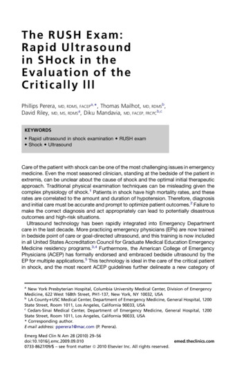
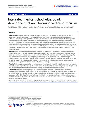
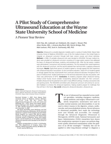
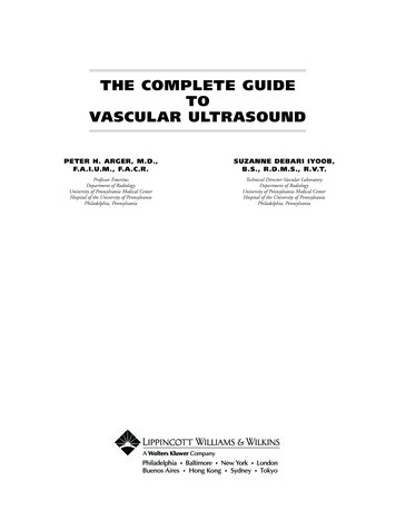
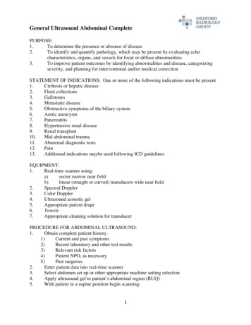
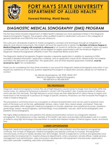
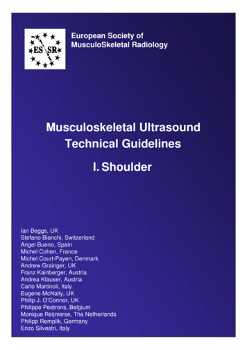
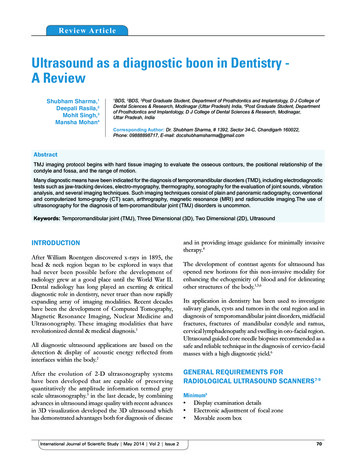
Sharma, et al.: Ultrasound in Dentistryapplications in image-guided neurosurgery as an alternativeapproach to open magnetic resonance (MR)and intrainterventional computed tomography (CT).10,11of 2D ultrasound images, and differ only in the methodused to determine the position and orientation of these2d images within the 3D image volume being examined.4In a 3D ultrasound examination, the 2D ultrasound imagesare combined by a computer to form an objective 3D imageof the anatomy and pathology (Figures 1-4). This imagecan then be viewed, manipulated and measured in 3D bythe physician on the same or another computer. Also, a 2Dcross-sectional image can be generated in any orientation,without restriction, at any anatomical site, which may easilybe registered with a previous or subsequent 3D image.Thus, 3D ultrasound imaging promises to overcome thelimitations of 2D ultrasound imaging.4,10-12AdvantagesScanning TechniquesMost 3D ultrasound imaging systems make use ofconventional 1D ultrasound transducers to acquire a seriesFigure 1: Ultrasonographic picture of the swelling showingoval-shaped lesion with anechoic internal echo pattern andunchanged posterior wall echo. These features are suggestiveof a dentigerous cystFigure2 : Ultrasonography picture showing anechoic lesionin the region of buccal space suggesting of buccal spaceabscess. (USG, 8 MH2 probe)731. 3-D imaging permits volume data to be viewedin multiple imaging planes and allows accuratemeasurement of lesion volume.22. It offers both for the diagnosis of disease and inproviding image guidance for minimally invasivetherapy.43. The major advantage of 3-D US over existing intraoperative imaging techniques are its comparatively lowcost and simplicity of use.104. Its ability to measure the length, area or volume oforgans or lesions in arbitrary orientations.4Figure 3: Longitudinal sonogram of the parotid gland. Unilateralhypoechogenic swelling of the gland, color Doppler revealshyperemia. Acute sialoadenitis was diagnosedFigure 4: Transverse sonogram of the left parotid gland.Echogenic swelling of both parotid glands was present.The deep parts of the gland are not visualized due to strongacoustic attenuation. Sialoadenosis was diagnosedInternational Journal of Scientific Study May 2014 Vol 2 Issue 2
Sharma, et al.: Ultrasound in DentistryMeasurement Accuracy with 3D Ultrasound1. Distance measurement - With a 3D image, distancemeasurements need not be made in the plane of anacquired 2D image, but instead can be made in anyorientation.42. Measurement of cross-sectional area using 3Dultrasound- Using the multiplanar reformatting(MPR)technique, the 3D image can be ‘sliced’ in anyorientation, to obtain the optimal cross section for theorgan measurement.43. Volume measurement using 3D ultrasound- Theavailability of 3D images allows the measurementof organ volume using either manual or algorithmictechniques.4Doppler UltrasoundDoppler ultrasound is based upon the Doppler Effect.Christian Andreas Doppler (Austrian mathematician andphysicist)1841 proposed that the observed color of a starwas caused by a spectral shift of white light that occurredbecause of the motion of the star relative to the earth.Doppler used analogies based on the transmission oflight and sound. Although his theory on light was in error,Doppler’s theories on the change in frequency of soundwaves were correct.6The Doppler Effect – the Doppler Effect, as the theorybecame known, is defined as “the observed changes infrequency of transmitted waves when relative motion existsbetween the source of the wave and an observer”. Thistheory was applied to many aspects of science, includingastronomy and medicine.6ADVANTAGES1. It is a dynamic and readily available technique.132. It is particularly useful in the examination of superficialstructures.133. It is widely available and relatively inexpensive.124. It is a non-invasive technique.125. It is well tolerated by the patient.136. It does not interfere with normal function.147. Artifacts are few.138. The technique is highly acceptable to most patients.139. Images are rapidly acquired.1310. Images are simple to store and retrieve.1511. Images obtained are easy to read once the observer istrained.1612. It can be performed without heavy sedation.1213. It has no known cumulative biological effects.1814. It is proven to be reproducible and simple.1715. Equipments are portable.19International Journal of Scientific Study May 2014 Vol 2 Issue 216. It is easily accessible and painless.2017. It is a less discomfort, relatively rapid and examinationcan be performed even at the patient’s bedside.2018. Its absolute non ionizing nature.2019. Equipments are relatively cheap.1620. It is convenient to use.1621. Its possibility of real time imaging.2122. It helps to distinguish between solid and cystic lesions.2023. Its ability to detect non calcified pathological entitiessuch as sialoliliths.21DISADVANTAGES1. The technique is very operator- and equipmentdependent.122. Clinically only the bone surfaces and not the wholecortex or spongiosa can be visualized in intact donedue to ultrasound frequencies.223. It has to be performed by experienced investigators.194. Images when archived they may be difficult to orientateand to interpret unlike CT and MR scans, which haveacquired in standard reproducible scans.135. The difficulty of picturing the TMJ using ultrasoundsdepends on the limited accessibility of the deepstructures, especially the disc, due to absorption of thesound waves by the lateral portion of the head of thecondyle and the zygomatic process of the temporalbone.236. Ultrasound images are affected by inherent noiseaccompanying the signal returned to the transducerwhich makes interperatation of the static images, andsometimes the dynamic ones as well and a nonmovingobject will vary in appearance because of this noise.157. Ultrasonography waves do not visualize bone or passthrough air, which acts as an absolute barrier duringboth emission and reflection.23Depending on the application and ultrasonic intensities itis divided into twoDiagnostic ultrasound – the ultrasonic intensities used aretypically 5 to 500 mW/cm2 and it includes: Swellings in orofacial region Salivary glands disorders Periapical lesions Lymph nodes – benign/malignant Intraosseous lesions Temporomandibular disorders Assessment of masticator y muscles intemporomandibular dysfunction Congenital vascular lesions of head and neck Primary lesions of the tongue74
Sharma, et al.: Ultrasound in Dentistry Fractures of mandibular condyle and ramus andmidfacial fractureDetecting the foreign bodiesDistracted mandibular boneMiscellaneous lumps and bumps of the head and neckUltrasound guided Core needle biopsy Submandibular gland injection of botulinum toxinfor hypersalivation in cerebral palsy Basket retrieval of salivary stones 2. Therapeutic ultrasound – use intensities of 1 to3 W/cm2 and it includes – Myofascial pain Temporomandibular joint dysfunction Ultrasound guided lithotripsy of salivary calculi usingan electromagnetic lithotripter Bone healing and oestointegration Oral Cancer Healing of full thickness excised skin lesion. Other applications Ultrasonic descaling Modifications of the ultrasonic descaling1. Endodontics2. Surgical applications3. Other dental uses4. Ultrasonic cleaning bathsSUMMARY & CONCLUSIONRadiography has been widely used for obtaining acomprehensive overview of the maxillofacial complex.The clinical use of Radiography is limited by theuncertainty regarding the actual dimensions of structures.24Ultrasonography has revolutionized the world of medicalimaging as a diagnostic and therapeutic aid. Thoughdiagnostic ultrasound has been used as a reliable diagnostictool in the medical field but still not found its place as aroutine diagnostic aid in the orofacial region.It is recognised as one of the most risk-free methods ofevaluating any disease in the human. Ultrasound real timeimaging has wide application in numerous diagnostic fields.It has been suggested that it can provide useful informationfor the assessment of TMJ disorders. Despite the limitationsthat it is operator dependent, better standardization isrequired and normal parameters must be set and it remainspotentially useful as an alternative imaging technique formonitoring TMJ disorders particularly for the diagnosis ofarticular disc displacement and joint effusion.75It may be acceptable treatment of choice in many types ofclinical procedures involving maxillofacial bone.It has several advantages over conventional radiographynamely its non- invasive nature, easy reproducibility,possibility of real time imaging, its ability to detectnon calcified pathological entities, relatively rapid andinexpensive 14.15.16.17.18.19.20.Douglas L. Miller, Michalakis A. Averkiou, Andrew A. Brayman etal. Bioeffects considerations for diagnostic ultrasound contrast agents.J Ultrasound Med. 2008; 27:611-632.Carol M. Rumack, Stephanie R. Wilson, J. William Charboneau, Diagnosticultrasound. volume 1; edition 3rd.W.F. Sample. Gray scale ultrasonography. The western Journal of Medicine.1976;124(5):403.Aaron Fenster, Donal B Downey and H Neale Cardinal. Three-dimensionalultrasound imaging. Phys Med Biol. 2001;46(5):R67-R99.P.A.Dijkmans, L.J.M Juffermans, R.J.P Musters, et al. Microbubblesand ultrasound: from diagnosis to therapy. Eur J Echocardigraphy.2004;5:245-256.Paul G. Newman and Grace S. Rozycki. The history of ultrasound. Surgicalclinics of North America. 1998;78(2):179-195.P.E.S Palmer. Manual of diagnostic ultrasound. Published by the worldhealth organization in collaboration with the world federation for ultrasoundin medicine and biology; 2007.Courtney M. Townsend, R. Daniel Beauchamp, B. Mark Evers andKenneth L. Mattox. Sabiston textbook of surgery the biological basis ofmodern surgical practice; volume 1 edition 18th 2009.Board of the Faculty of Clinical Radiology. Standards for ultrasoundequipment. The royal college of radiologists. Feb 2005.Alexis Roche, Xavier Pennec, Grégoire Malandain, and Nicholas Ayache.Rigid Registration of 3-D Ultrasound with MR Images: A New ApproachCombining Intensity and Gradient Information. IEEE transactions onmedical imaging. 2001;20(10):1038-49.Tong S, Dwney D B, Cardinal H N and Fenster A. A three-dimensionalultrasound prostate imaging system. Ultrasound Med. Biol. 1996;22:735-46.Elliot T L, Downey D B, Tong S, McLean C A and Fenster A. Accuracy ofprostate volume measurements in vitrousing three-dimensional ultrasound.Acad. Radiol. 1996;3(5):401-6.Rachel S. Oeppen, Daren Gibson and Peter A. Brennan. An update on theuse of ultrasound imaging in oral and maxillofacial surgery. British Journalof Oral and Maxillofacial Surgery. 2010;48(6):412-418.I Rozylo-Kalinowska, A Brodzisz, E Galkowska et al. Application ofDoppler ultrasonography in congenital vascular lesions of the head andneck. Dentomaxillofacial Radiology. 2002;31:2-6.Stanley Braun, J. Shaun Hicken. Ultrasound Imaging of Condylar Motion:A Preliminary Report. Angle Orthod. 2000;70:383-386.M Gundappa, SY Ng, EJ Whaites. Comparison of ultrasound, digitaland conventional radiography in differentiating periapical lesions.Dentomaxillofacial Radiology. 2006;35(5):326-333.Hayashi T. Application of ultrsonography in Dentistry-Review. JapaneseDental Sciences.2012;28(1):5-15.Fikret Satiroglu, Tülin Arun, Fulya Isik. Comparative data on facialmorphology and muscle thickness using ultrasonography. EuropeanJournal of Orthodontics. 2005; 27(6):562-567.R. E. Friedrich, M. Heiland, S. Bartel-Friedrich. Potentials of ultrasound inthe diagnosis of midfacial fractures. Clin Oral Invest. 2003;7:226-229.Vinod Vijay Chandar, M. Venkateswarlu. Utility of ultrasonography asadjunct to diagnosis in certain orofacial lesions over the clinical andradiological evaluation: A comparative study. Journal of Indian Academyof Oral Medicine and Radiology. 2009;21(1).International Journal of Scientific Study May 2014 Vol 2 Issue 2
Sharma, et al.: Ultrasound in Dentistry21.22.Shivanand B Bagewadi, Mahima VG, Karthikeya Patil. Ultrasonography ofswellings in orofacial region. Journal of Indian Academy of Oral Medicineand Radiology. 2010;22(1):18-26.R.E. Friedrich, K. Plambeck, S. Bartel-Friedrich et al. Limitations of B-scanultrasound for diagnosing fractures of the mandibular condyle and ramus.Clin Oral Invest. 2001;5:11-16.23.24.Marcello Melis, Simona Secci and Caroline Ceneviz. Use of ultrasonographyfor the diagnosis of temporomandibular joint disorders: A review. AmericanJournal of Dentistry.Chandak Shruti, Shalini Saraswat, Vijai Pratap Omprakash. Role ofDentascan V/S Radiography in the Evaluation of Tumours of the Jaw.International Journal of Scientific Study. 2013;1(3):77-80.How to cite this article: Shubham Sharma, Deepali Rasila, Mohit Singh, Mansha Mohan. "Ultrasound as a diagnostic boon in Dentistry-AReview". Int J Sci Stud. 2014;2(2):70-76.Source of Support: Nil, Conflict of Interest: None declared.International Journal of Scientific Study May 2014 Vol 2 Issue 276
Its application in dentistry has been used to investigate salivary glands, cysts and tumors in the oral region and in diagnosis of temporomandibular joint disorders, midfacial fractures, fractures of mandibular condyle and ramus, cervical lymphadenopathy and swelling in oro-facial region. Ultrasound guided core needle biopsies recommended as a