Transcription
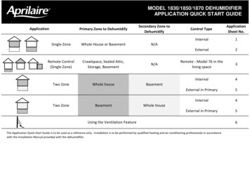
MODEL 1830/1850/1870 DEHUMIDIFIERAPPLICATION QUICK START GUIDEApplicationPrimary Zone to DehumidifySecondary Zone toDehumidifySingle ZoneWhole House or BasementN/ARemote Control(Single Zone)Crawlspace, Sealed Attic,Storage, BasementN/ATwo ZoneTwo ZoneWhole houseBasementBasementWhole houseControl TypeApplicationSheet No.Internal1External2Remote - Model 76 in theliving space3Internal4External in Primary5Internal4External in Primary5Using the Ventilation FeatureThe Application Quick Start Guide is to be used as a reference only. Installation is to be performed by qualified heating and air conditioning professionals in accordancewith the Installation Manual provided with the dehumidifier.6
Application Sheet 1 – Single Zone Using Internal ControlParts Needed (additional parts may be required):Model 1830/1850/1870Thermostat wireInsulated duct20A Outlet (1870 only)Duct fittings & hardwareGrilles (if required)Drain Pan and Float Switch (if required)Main Return to Main Return - RecommendedSUPPLYRETURNHVAC EQUIPMENTMain Return to Main SupplySUPPLYRETURNHVAC EQUIPMENTFigure 3 Wiring (shown without “disable withAC” feature being used)Sequence of OperationDedicated Return to Main Supply or ReturnSUPPLYRETURNHVAC EQUIPMENTFigure 1 Dehumidifier Ducted to HVAC SystemFigure 2 Dehumidifier Ducted DirectlyThe dehumidifier will automatically “sample”the air by turning on its blower (and the HVACblower if this option has been wired – seeFigure 3), and measuring the relative humidity(RH) once every hour. Sampling will also occurwhen the RH setting is lowered using the UP orDOWN buttons on the control.During sampling, if the RH of the air is abovethe setting the dehumidifier, the compressorwill turn on. The compressor, dehumidifierblower and HVAC system blower (if on) turnsoff when the RH of the air is 3% RH below thesetting.
Application Sheet 2 – Single Zone Using External ControlParts Needed (additional parts may be required):Model 1830/1850/1870Thermostat wireInsulated duct20A Outlet (1870 only)Duct fittings & hardwareModel 76, Model 8620Grilles (if required)or Model 8910 controlDrain Pan and Float Switch (if required)Main Return to Main Return - RecommendedSUPPLYRETURNHVAC EQUIPMENTMain Return to Main SupplySUPPLYRETURNHVAC EQUIPMENTFigure 3 Wiring (shown without “disablewith AC” feature being used)External ControlDedicated Return to Main Supply or ReturnSUPPLYRETURNHVAC EQUIPMENTFigure 1 Dehumidifier Ducted to HVAC SystemFigure 2 Dehumidifier Ducted DirectlyThe external control (i.e. Aprilaire Model 76Dehumidifier Control, Model 8620Thermostat or Model 8910 Home ComfortControl) must have a normally open (NO –all Aprilaire controls are normally open type)or normally closed (NC) dry contact output,and must be installed in the space that isgoing to be dehumidified. Select the type ofcontrol using the NO/NC dip switch on thedehumidifier control.Sequence of OperationWhen the external control calls fordehumidification, the dehumidifier blowerthe HVAC blower (if this option has beenwired – see Figure 3) turn on, then threeseconds later the compressor turns on. Allwill turn off when the external control stopscalling for dehumidification.
Application Sheet 3 – Remote Control Using Model 76 ControlParts Needed (additional parts may be required):Model 1830/1850/1870Model 76 Dehumidifier ControlInsulated ductThermostat wireDuct fittings & hardware20A Outlet (1870 only)Grilles (if required)Drain pan and float switch (if required)FLOATDH DHSWITCHNCNOMODEL 76 REMOTECONTROLABC/R/ DHDHFigure 1 Dehumidifier Ducted DirectlyAfter wiring the Model 76 to the dehumidifier as shown, use thepower switch located on the outlet panel of the dehumidifier topower up the dehumidifier. The dehumidifier control shoulddisplay “OFF”.HVAC EQUIPGh Rf Cf Gs W YSet Up the Dehumidifier for Remote ControlDEHUMIDIFIERCONTROLBOARDFigure 2 Wiring the Control1. Enter the Installer Set-Up menu by pressing and holding the“Mode” button on the dehumidifier control for 3 seconds;“REMOTE DISABLED” will appear on the display.2. Press the Up or Down button to select “REMOTE ENABLED”.3. Press the Mode button again to complete set up (“DONE”will appear on the display).Sequence of OperationThe Model 76 Dehumidifier Control can be installed in any convenient location within the living space while thedehumidifier is installed in the space that is going to be dehumidified such as a crawl space, attic or basement. Therelative humidity (RH) displayed on the Model 76 is the RH in the space where the dehumidifier is located – thedehumidifier communicates this to the Model 76. Changes to the dew point setting (1 – less dry, 7 – more dry) aremade at the Model 76 and communicated to the dehumidifier. The dehumidifier can be turned on and off using theON/OFF buttons of the Model 76.Once every hour the dehumidifier will turn on its blower and sample the air in the zone to be dehumidified (samplingwill also occur whenever the dew point setting is raised). If the dew point of the air is higher than the setting on thecontrol, the dehumidifier compressor will turn on. When the dew point of the air is below the setting on the Model 76Control, the dehumidifier will turn off.When the Model 76 Control is wired to the dehumidifier in this application and after completing the set up (see Set Upthe Dehumidifier for Remote Control above), “REMOTE” will appear on the display of the dehumidifier control.
Application Sheet 4 – Two Zone using Internal ControlTO/FROM PRIMARY ZONETO BE DEHUMIDIFIEDParts Needed (additionalparts may be required):Model 1830/1850/1870Insulated ductThermostat wireDuct fittings & hardware20A Outlet (1870 only)Drain pan and float switch (ifrequired)Grilles4522 Damper Kit (includes:2 – 8” dia N.O. dampers,2 – 8” dia N.C. dampers andone 40VA, 24VAC plug-intransformer)EXISTING WIRENEW WIRENORMALLYOPEN DAMPERFLOATDH DHSWITCH20 VA (MIN.) AC EQUIPGh Rf Cf Gs W YCFigure 3 WiringSet Up the Dehumidifier for Zoning1.2.3.4.NORMALLYOPEN DAMPERFigure 1 Duct/Damper Layout withWhole House as Primary Zone24VACRNORMALLYCLOSEDDAMPERTO/FROM SECONDARY ZONE TOBE DEHUMIDIFIEDN.C. DAMPERSN.O. DAMPERSHVAC EQUIPMENTNORMALLYCLOSEDDAMPERDEHUMIDIFIERCONTROL BOARDNCNOTO/FROM SECONDARY ZONETO BE DEHUMIDIFIEDNORMALLYOPEN DAMPERNORMALLYCLOSEDDAMPERHVAC EQUIPMENTNORMALLYOPEN DAMPERNORMALLYCLOSEDDAMPERTO/FROM PRIMARY ZONE TO BEDEHUMIDIFIEDFigure 2 Duct/Damper Layout withBasement as Primary ZoneSequence of OperationAdjust the relative humidity (RH) setting on thedehumidifier control; this will be the setting for both thePrimary and Secondary Zone. Once an hour, thedehumidifier will “sample” the air in the Primary Zone.If there is no need for dehumidification in the PrimaryZone the dehumidifier will then sample the air in theSecondary Zone.When sampling in the Primary Zone the dehumidifierwill energize the dampers and then turn on its blower(and the HVAC System blower if wired as shown inFigure 3), to measure the RH of the air. If the RH of theair is above the setting, the compressor will turn on. Ifthe Primary Zone does not need dehumidification, thedampers are de-energized and the HVAC System Blower(if on) is turned off while the dehumidifier blowercontinues to run to sample the air in the SecondaryZone. If the RH of the air in the Secondary Zone is abovethe setting, the compressor will turn on.With “OFF” showing on the control, press the Mode button for 3 seconds to enter the Installer Set Up menuPress the Mode button until “ZONE DISABLED” appears.Press the Up or Down button to change to “ZONE ENABLED”.Press the Mode button repeatedly until “DONE” shows on the display.
Application Sheet 5 – Two Zone with External Control in Primary ZoneTO/FROM PRIMARY ZONETO BE DEHUMIDIFIEDParts Needed (additionalparts may be required):Model 1830/1850/1870Model 76, Model 8620 orModel 8910 controlInsulated ductThermostat wireDuct fittings & hardware20A Outlet (1870 only)Drain pan and float switch (ifrequired)Grilles4522 Damper Kit (includes: 2– 8” dia N.O. dampers,2–8” dia N.C. dampers and one40VA, 24VAC plug-intransformer)NORMALLYCLOSEDDAMPERHVAC EQUIPMENTNORMALLYOPEN DAMPERNORMALLYCLOSEDDAMPERNORMALLYOPEN DAMPERTO/FROM SECONDARY ZONE TOBE DEHUMIDIFIEDFigure 1 Duct/Damper Layout withWhole House as Primary ZoneTO/FROM SECONDARY ZONETO BE DEHUMIDIFIEDNORMALLYOPEN DAMPERNORMALLYCLOSEDDAMPERHVAC EQUIPMENTNORMALLYOPEN DAMPERNORMALLYCLOSEDDAMPERTO/FROM PRIMARY ZONE TO BEDEHUMIDIFIEDFigure 2 Duct/Damper Layout withBasement as Primary ZoneSequence of OperationREMOTEDAMPERSODT - A B SENSOR VENT DEHFigure 3 WiringThe external control (i.e. Model 76 Control or Model 8910Home Comfort Control) provides on-demand control of thedehumidifier for the Primary Zone. When the Primary Zonecalls for dehumidification, the dehumidifier energizes thedampers, and turns on its blower and compressor. Thedehumidifier will also turn on the HVAC System Blower if wiredas shown in Figure 3). The Primary Zone demand will overridean existing Secondary Zone demand.The Secondary Zone is controlled by the relative humidity (RH)setting at the dehumidifier control. Once an hour, orimmediately after dehumidifying the primary zone, thedehumidifier will “sample” the air in the Secondary Zone.When sampling, the dampers are not energized while thedehumidifier blower runs and the RH is measured If the RH isabove the setting on the control, the compressor will turn onand the Secondary Zone will be dehumidified.Set Up the Dehumidifier for Zoning and External Control1.2.3.4.5.6.Press the Mode button for 3 seconds to enter the Installer Set Up menuPress the Mode button until “ZONE DISABLED” appears.Press the Up or Down button to change to “ZONE ENABLED”.Press the Mode button again to show “EXTERNAL DISABLED”Press the Up or Down button to change to “EXTERNAL ENABLED”Press the Mode button repeatedly until “DONE” shows on the display.
Application Sheet 6 – Using the Ventilation Feature of the DehumidifierParts needed for ventilation:Model 6506 damperModel 8052 OutdoorTemperature Sensor(optional)Model 4010 10VATransformer6” Insulated Duct, fittingsand hardwareIntake HoodThermostat wireFigure 1 Ventilation Duct LocationFigure 2 Ventilation WiringInstall a ventilation duct with a normally closed Model 6506 damper to the return duct of the HVAC system (see Figure1) and wire the dehumidifier to the HVAC system as shown in Figure 2. The outdoor temperature (ODT) sensor is usedto limit ventilation if the outdoor temperature gets too hot or too cold (see Set Up the Dehumidifier for Ventilationbelow), if temperature limits are not needed, the ODT sensor does not have to be installed. Follow the set upinstructions below and set the number of minutes per hour that ventilation will be needed (refer to the InstallationManual for details on determining how much ventilation is needed). Whenever the heating or cooling turns on, orwhen the dehumidifier turns on, the dehumidifier will open the damper and bring in fresh outdoor air. If theequipment doesn’t run for the set number of minutes, the dehumidifier will turn on HVAC fan at the end of the hour toensure ventilation needs are met.Set Up the Dehumidifier for Ventilation1.2.3.4.With “OFF” showing on the control, press the Mode button for 3 seconds to enter the Installer Set Up menuPress the Mode button until “VENT DISABLED” appears.Press the Up or Down button to change to “VENT ENABLED”.Press the Mode button and “VENT TIMED” will be displayed. Press the Up or Down button to toggle between:TIMED: no temperature limitsAUTO – B: Ventilation not allowed if ODT 100 F or ODT 0 F; allowed only when heating if 0 F ODT 20 .AUTO – C: Ventilation not allowed if ODT 100 F or ODT 0 FAUTO – D: Ventilation not allowed if ODT 90 F; allowed only when heating if 0 F ODT 40 F5. Press the Mode button, the use the Up and Down buttons to set the Vent Time (minutes/hour).6. Press Mode repeatedly until “DONE” appears on the display.Using the Dehumidifier to Pre-Condition the Ventilation AirODTSENSORMODEL 6506NORMALLYCLOSED DAMPERFigure 3 Dehumidify Ventilation AirThe dehumidifier can be used to removemoisture from the ventilation air before it isdelivered to the home. Install the ventilationduct to the dehumidifier inlet duct as shown inFigure 3. The control on the dehumidifier mustbe used for the Primary Zone (i.e. an externalcontrol cannot be used) in this installation. Ifthe RH of the incoming air is above the settingon the control the air will be dehumidified.
10010431B2206146AP.O. Box 1467 Madison, WI 53701-1467 Phone: 800/334-6011 Fax: 608/257-4357 www.aprilairepartners.comPrinted in U.S.A 2013 Aprilaire – A division of Research Products Corp.
Sequence of Operation When the external control calls for dehumidification, the dehumidifier blower the HVAC blower (if this option has been wired - see Figure 3 ) turn on, then three seconds later the compressor turns on. All will turn off when the external control stops calling for dehumidification. HVAC EQUIPMENT SUPPLY RETURN SUPPLY RETURN