Transcription
USER’S HANDBOOKUSER’S HANDBOOKINCLUDING INSTALLATION MANUALAND LOG BOOKSERIAL NUMBER LABELEMERGENCY LOCATOR TRANSMITTERMODEL ADT406² AF/APPN: 01N65900IN THE COSPAS / SARSAT SYSTEMIssued byELTAF661414 Place Marcel Dassault31702 BLAGNACFrancewww.elta.frDocumentation P/N: 02E62356 Rev GInitial issue: Jun 30/02Title PageMay 16/14
USER’S HANDBOOKPAGE INTENTIONALLY LEFT BLANK
USER’S HANDBOOKLIST OF dateUpdateUpdateUpdateUpdateUpdateJun 30/02Apr 30/03Jul 30/03Jun 30/06Oct 01/06Oct 11/07May FFEE.LABRIFFEE.LABRIFFEE.LABRIFFEC.CRESPA DOMPSPage 1May16/14
USER’S HANDBOOKPAGE INTENTIONALLY LEFT BLANKPage 2BLANK
USER’S HANDBOOKLIST OF EFFECTIVE PAGESCHAPTER/SECTIONPAGETITLE PAGEDATEMay 16/14LISTE OF UPDATES12Oct 11/07BLANKLIST OF EFFECTIVE PAGE34Oct 11/07BLANKTABLE OF ILLUSTRATIONS56Oct 11/07BLANKLEADING PARTICULARS78Oct 11/07BLANKTABLE OF 03132333435Oct 11/07BLANKOct 11/07Oct 11/07Oct 11/07Oct 11/07Oct 11/07Oct 11/07Oct 11/07Oct 11/07Oct 11/07Oct 11/07Oct 11/07Oct 11/07Oct 11/07Oct 11/07Oct 11/07Oct 11/07Oct 11/07Oct 11/07Oct 11/07Oct 11/07Oct 11/07Oct 11/07Oct 11/07Oct 11/07Oct 11/07CHAPTER/SECTIONAppendix AAppendix BPAGEDATE1234567891011121314Oct 11/07Oct 11/07Oct 11/07Oct 11/07Oct 11/07Oct 11/07Oct 11/07Oct 11/07Oct 11/07Oct 11/07Oct 11/07Oct 11/07Oct 11/07Oct 11/071234567891011121314-Oct 11/07Oct 11/07Oct 11/07Oct 11/07Oct 11/07Oct 11/07Oct 11/07Oct 11/07Oct 11/07Oct 11/07Oct 11/07Oct 11/07Oct 11/07Oct 11/07Oct 11/07Oct 11/07Page 3May 16/14
USER’S HANDBOOKPAGE INTENTIONALLY LEFT BLANKPage 4BLANK
USER’S HANDBOOKTABLE OF ILLUSTRATIONSPageFigure 1 : COSPAS/SARSAT - System Principle12Figure 2 : ELT ADT 406² AF / AP Presentation14Figure 3 : ELT ADT 406² AF / AP – Dimensions (Basic Configuration)16Figure 4 : Tolerances on the Axis for Installation of the ELT ADT 406² AF / AP23Figure 5 : Automatic activation direction selection for ELT ADT 406² AF / AP24Figure 6 : Installation of the ELT ADT 406² AF / AP - Drilling Pattern Dimensions25Figure 7 : ELT ADT 406² AF / AP Installation - Wiring Diagram27Figure 8 : ELT ADT 406² AF / AP - Detailed Description35Page 5Oct 11/07
USER’S HANDBOOKPAGE INTENTIONALLY LEFT BLANKPage 6BLANK
USER’S HANDBOOKLEADING PARTICULARSCAUTION 1 : THIS TRANSMITTER IS AUTHORIZED FOR USE ONLY DURING SITUATIONS OF GRAVEAND IMMINENT DANGER.CAUTION 2 : IT IS IMPERATIVE THAT EACH BEACON OWNER REGISTERS THEIR BEACON. CONTACTELTA OR APPROVED AGENT TO OBTAIN THE INFORMATION RELATIVE TO THISREGISTRATION.CAUTION 3 : THE BEACON MUST IMPERATIVELY BE PROGRAMMED WITH THE RELEVANTIDENTIFICATION AUTHORIZED BY THE LOCAL AIRWORTHINESS.CAUTION 4 : ONCE THE BEACON HAS BEEN PROGRAMMED, IT IS GENERALY ASSIGNED TO ANAIRCRAFT (NAME AND IDENTIFICATION). IF THIS BEACON IS USED ON ANOTHERAIRCRAFT IT WOULD HAVE TO BE REPROGRAMMED (NEW NAME AND IDENTIFICATION).CAUTION 5 : BEFORE INSTALLING OR USING THIS EQUIPMENT, THE VALIDITY OF THE INFORMATIONON THE BEACON LABEL MUST IMPERATIVELY BE CHECKED.Page 7Oct 11/07
USER’S HANDBOOKPAGE INTENTIONALLY LEFT BLANKPage 8BLANK
USER’S HANDBOOKTABLE OF CONTENTSPAGE1. INTRODUCTION TO THE COSPAS-SARSAT SYSTEMA. The COSPAS-SARSAT systemB. System organizationC. The distress frequenciesD. ELTA and the COSPAS-SARSAT system2. GENERAL DETAILS OF THE ELT ADT 406² AF / APA. Purpose of the ELT ADT 406² AF / APB. Characteristics3. DESCRIPTION OF THE ELT ADT 406² AF / AP AND OF THE AIRCRAFT COMPONENTSA. General descriptionB. Detailed description11111113131414171919194. INSTALLATION OF THE ELT ADT 406² AF / AP23A. GeneralB. Installation of the beacon on the aircraftC. External antenna installationD. Remote control unit installationE. Installation and configuration of the beacon23232627285. UTILIZATION OF THE ELT ADT 406² AF / APA. Automatic activationB. Manual activationC. Beacon shutdownD. Beacon self-test6. MAINTENANCE OF THE ELT ADT 406² AF / APA. Beacon self-testB. Maintenance periodicity tableC. Battery replacementD. Battery discardingE. Test to do at the time of a beacon return in workshop2929293031333333343434Page 9Oct 11/07
USER’S HANDBOOKPAGE INTENTIONALLY LEFT BLANKPage 10BLANK
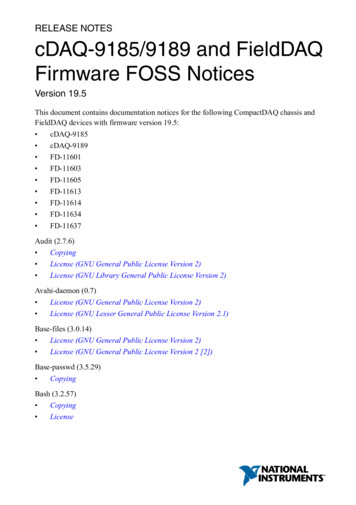
USER’S HANDBOOK1. INTRODUCTION TO THE COSPAS-SARSAT SYSTEMA. The COSPAS-SARSAT* systemThe purpose of the COSPAS-SARSAT satellite system is to detect and locate all distress signalstransmitted by aeronautical, maritime or land-based beacons, for the search and rescue organizations.This program is the result of an international collaboration between the United States, Canada and Franceon the one hand (SARSAT project), and Russia on the other hand (COSPAS project). These two projectsare fully compatible.Since the first results were obtained several countries have joined the program. Several other countrieshave shown an interest and will soon be joining the COSPAS-SARSAT system partners.ELTA in relation with CNES (French National Space Agency) has developed the complete range of productsrequired for COSPAS-SARSAT system operation.Following an in-depth study phase, ELTA has arrived at highly conclusive technical results, andexperimental and operational use of the "ground" equipment have proven this equipment's reliability andease-of-use.B. System organization (Ref. Fig. 1)In the COSPAS-SARSAT system, space equipment is placed on board several satellites in low near-polarorbit to capture transmissions from emergency transmitters and to retransmit these signals to specializedground stations called Local User Terminals (LUT). These ground stations determine the position of theemergency transmitters and then retransmit the position data to the designated Mission Control Centers(MCC). The MCCs in turn retransmit these data to the appropriate Rescue Coordination Centers (RCC) sothat they can start the search and rescue operations.*COSPAS-SARSAT :COSPAS Kosmicheskaya Sistyema Poiska Avariynych SudovSARSAT Search and Rescue Satellite-Aided TrackingPage 11Oct 11/07
USER’S HANDBOOKLegend :ELT : Emergency Locator TransmitterEPIRB : Emergency Position Indicating Radio BeaconPLB : Personal Locator BeaconRCC: Rescue Coordination CentersMCC: Mission Control CentersLUT : Local User TerminalsCOSPAS/SARSAT – System PrincipleFigure 1Page 12Oct 11/07
USER’S HANDBOOKC. The distress frequenciesThere are several advantages to using the 406 MHz frequency :– Worldwide coverage: locating is not only possible in real-time within a radius of 2,500 km around thestation, but also in global mode outside this zone since the satellites memorize the messages on the 406MHz frequency. Location process uses Doppler effect.– Locating accuracy: 2 km as opposed to 10 to 15 km in the 121.5 MHz or 243 MHz frequencies. It shouldbe noted however that the 406 MHz beacons also transmit 121.5 MHz and 243 MHz signals whichenable the final approach of the rescue teams in homing mode.– Information reliability: the structure of the digital signal transmitted by these beacons makes it possible tobe sure that there is actually a distress situation, as well as to identify automatically the mobile in distresswhich is vital for rescue operations.– Unique identification: each beacon has it’s own identification information.D. ELTA and the COSPAS-SARSAT system(1)406 MHz distress beacons:These beacons transmit to the satellites a digital message which identifies them and gives their position,as well as a signal that facilitates the final approach of the rescue teams.They are suitable for all types of use (maritime, aeronautical and land) and can, depending on the model,be activated manually or automatically. They are designed to function in the most extreme conditions witha high degree of reliability.(2)Satellites low earth orbiting:At least four satellites are permanently operational. Since their orbit is near-polar, in the worst case everypoint on Earth is overflown every two hours.In a ground station's visibility zone, the satellites directly transmit the messages captured in that zone, andalso any messages from the zones not covered that they have stored in memory.(3)Geo-stationary satellites are now available in the system and offer faster detection capability (close to 5minutes) but require a GPS receiver to supply location that is sent via C/S message.(4)Ground reception stations:The zone effectively covered (or visibility zone) is a circle with a radius of 2,500 km around the station.These stations receive (via the satellites) and process, in real time, the messages from the beaconsactivated in their visibility zone and, in batch mode, the messages from the 406 MHz beacons activatedoutside that zone and memorized by the satellites.Automatic processing of the 406 MHz digital messages allows the beacons to be located and the carriermobile to be identified.Page 13Oct 11/07
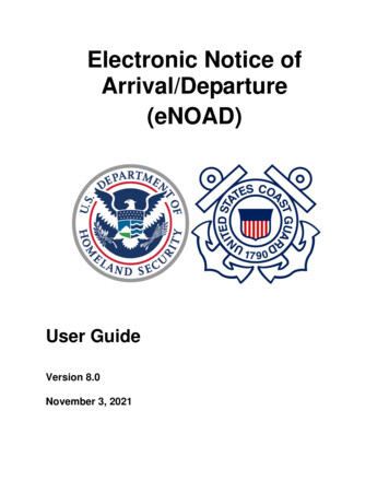
USER’S HANDBOOK2. GENERAL DETAILS OF THE ELT ADT 406² AF / APA. Purpose of the ELT ADT 406² AF / AP (Ref. Fig. 2)The ELT ADT 406² AF / AP is an automatic distress beacon transmitter that incorporates means of fasteningin order to ease A/C installation.Metalic strapELT ADT 406² AF / AP- PresentationFigure 2The ELT ADT 406² AF / AP is designed to transmit a digital distress signal to satellites that are part of theCOSPAS/SARSAT SYSTEM.These satellites transmit the captured signal to the reception stations on the ground.This signal is transmitted on the 406.028 MHz frequency and is used to precisely locate and identify theELT ADT 406² AF / AP.It also transmits a 121.5 MHz and 243 MHz signal to facilitate the final approach of the distress scene(homing).It can be triggered manually or automatically by means of an acceleration sensor (G.switch in accordanceto EUROCAE ED-62 standard).This ELT meets the latest JAR OPS and ICAO recommendations.Page 14Oct 11/07
USER’S HANDBOOKAny encoding protocol defined by COSPAS/SARSAT can be used with ELT ADT 406² AF / AP includingcountry code assignation.The purpose of the Activation/Identification module on the top of the ELT transmitter is to store on boardthe A/C the Cospas-Sarsat identification. This module is attached to the A/C structure by the metallic strap.It will keep, on board the A/C, the Cospas-Sarsat Identification code. This module is transferable i.e. can beinstalled after removal on a new ELT transmitter (from the shop for maintenance as example). The operatoris sure that the new ELT transmitter will transmit the correct Cospas-Sarsat message upon activation.The identification code is stored in the non volatile memory and will not be lost upon, module or batteryremoval.The ADT 406 AF/AP ELT can be operated in a non-location protocol ELT when the transmitter is installedalone on board the A/C (Cospas-Sarsat Identification message encoded as “Short”), or in user locationprotocol ELT when the transmitter is installed with its optional dedicated “Navigation Interface” equipmentthat receive the A/C location (Latitude & Longitude) from the A/C data Bus (Cospas-Sarsat Identificationmessage encoded as “Long” and GPS accuracy transmitted is 4’ of angle as specified by Cospas-Sarsat).In CANADA the selected Cospas-Sarsat protocol must be the “Aircraft 24 bit address” either for short orlong Cospas-sarsat message.If the ownership change, the ELT shall be re-coded, new 15 digit Hex Code, with the appropriate countrycode and coding protocol as selected or required by the country of the new final operator. Contact ELTA foradditional details (www.elta.fr ).Page 15Oct 11/07
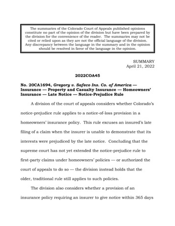
USER’S HANDBOOK74 [2.91]205 [8.07]ELT ADT 406² AF /AP - Overall Dimensions (Basic Configuration)(Other Back Up Antenna Configuration Are Available)Figure 3Page 16Oct 11/07
USER’S HANDBOOKB. Characteristics (Ref. Fig. 3)(1)ApprovalsADT 406² AF / AP is COSPAS/SARSAT approved (TAC # 131, first issue dated 15 July 2002, seeAppendix A page 1, for updated issue access the Cospas-Sarsat web ovedList.htm )ADT 406² AF / AP meets EUROCAE ED62, RTCA DO-204 & RTCA DO-183 standardsADT 406² AF / AP is JTSO 2C91a and JTSO 2C126 (JTSO N F.O. 089 dated 03 Oct. 2002, see AppendixA page 2)ADT 406² AF / AP is TSO C91a and TSO C126 (TSO letter dated February 24 2003, see Appendix A page4)ADT 406² AF / AP is TC approved (Transport Canada letter dated November 24 2006, see Appendix Apage 6)ADT 406² AF / AP is IC approved (Industrie Canada letter dated February 13 2007, see Appendix Apage 8)(2)Physical characteristicsHeight : 74 mmWidth : 160 mmLength : 234 mm (without back up antenna)Weight : 1.6 kg maximumBack up antenna lenght : 200 mm max(3)General characteristics(a)External antenna– Omnidirectionnal three-frequency antenna 50 access,– conform to COSPAS/SARSAT and EUROCAE ED-62 specifications.(b)Power supplyHigh energy batteries (2 series-connected packs), activable for 5 years. Autonomy 24 hours on 406.028MHz and greater than 60 hours at -20 C on 121.5&243 MHz.–––––Voltage: 6 VDC,capacity: 10.5 A/h,ELTA type number:00E64191,lithium manganese dioxide LiMMNO2 (solid cathode),battery servicing kit available: 02N60052 kit for one ELT.Page 17Oct 11/07
USER’S HANDBOOK(c) Radio-electrical characteristics1 406 MHz satellite transmitter–––––Frequency: 406.028 MHz,transmitter power: 5 W,modulation: "L" two-phase,transmission recurrence : 50 s,transmission duration : 440 or 520 ms.2 Associated homing transmitter––––Frequency121.5 MHz transmitter power243 MHz transmitter powermodulation– antenna gain: 121.5 MHz/243 Mhz or 121.5 MHz (selectable),: 200 mW,: 200 mW ,: AM (3K20A3X type) from, 1600 Hz to 300 Hz,up to four periods per second,: 1 dBi.(d)Environment characteristics– Operating temperatures– Storage temperatures: -20 C to 55 C,: -55 C to 85 C.Note: Ambient temperature is recommended for ELT storage in order to lower the battery self dischargerate.(e)Miscellaneous characteristics– Automatic activation level in accordance with EUROCAE ED-62 (internal G-switch, see Appendix Apage 13).Activation direction is selectable (4 possibe directions, see Figure 5),– color:orange in conformity with the international distress code,– self-test :transmission of one 406.028 MHz burst modulated with inverted framesynchronization and 1s transmission on 121.5 MHz, automation to off position (on the remotecontrol panel),– any COSPAS/SARSAT protocol available, ELT S/N A/C operator designator and S/N A/C 24 bits address A/C nationality and registration marking (recommended) Test (not for operational purposes)– any country code available,– can operate in short or long C/S message.For long message, location data (from on board GPS as exemple) is received from A/C data busthrough an optional interface module, P/N 01N6593(x),Page 18Oct 11/07
USER’S HANDBOOK– C/S identification stored in a transferable Activation/Identification Module (AIM) located on the top ofthe ELT case to ease maintenance on ELT,– dual antenna access. Primary for external antenna and secondary for permanent back up antennain case of failure detection on primary access.3. DESCRIPTION OF THE ELT ADT 406² AF / AP AND OF THE AIRCRAFT COMPONENTSA. General description(1)The ELT ADT 406² essentially consists of :––––an ADT 406² AF / AP beacon transmittera back up antenna,labels,an activation / identification module (AIM)(2)The ELT ADT 406² AF / AP basic aircraft components consists of :– a remote control unit,– an external antenna.B. Detailed description (Ref. Fig. 7)(1)The ADT 406² AF / AP beaconThe ADT 406² AF / AP beacon mainly consists of :– a power supply module,– an electronic assembly,– a mechanical assembly.The front face of the electronic assy is equipped with the following components :– a REMOTE CONTROL electrical SUB-D high density 15 pins female connector (7) for connecting upto the aircraft remote control panel or programming tools,– a BACK UP ANT. TNC female connector (10) for connecting up the antenna,– an EXT. ANT. BNC female connector (6) for connecting up the external antenna,– an ARMED/OFF/ON lockable toggle switch (9) for activating the beacon,– a TX indicator light (8) indicating beacon activation (real distress and self-test).Page 19Oct 11/07
USER’S HANDBOOK(2)The labels(a)Identification labelThis label indicates :– beacon name, manufacturer details,– the condition in which the beacon may be used (warning),– approval number, identification, part number, service bulletin, serial number and conditions on theuse of the beacon.JTSO-2C91a & 2C126(X)(b) How to use labelThis label gives indication on the electronic front face connectors and controls use versus mode ofoperation.Page 20Oct 11/07
USER’S HANDBOOK(c)Connectors location labelThis label indicates the location of the connectors on the front face of the electronic assy.(d)Identification labelThis label indicates the axis according to which the ELT ADT 406² AF / AP must be installed on theaircraft (see paragraph. 4.B.) for automatic activation (G-switch).It is fixed to the activation / identification module.Homing powerselectionOfficial 15 Hex.Homing pwr xx dBm(e)Batteries labelThis label indicates the batteries expiry date (next battery servicing).Page 21Oct 11/07
USER’S HANDBOOK(f) Additional labels for CANADAThere two additional labels related to CANADA application.– One is related to “Cospas-Sarsat” matters in CANADA– One is related to “Battery part clarification” for CANADAAn example of these new labels are presented here under.(3)ELT ADT 406² AF / AP aircraft components(a)Remote control unitThe remote control unit integrated in the aircraft cockpit consists of :– a RESET/TEST pushbutton,– an ELT ON indicator light,– a two-position ON/ARMED switch with safety cover (flip guard). The safety cover forces the switchto ARMED position. This switch must always remain in this position, except in the case of manualdistress triggering.The beacon is integrated in the aircraft as far aft as possible and so it must be connected to the remotecontrol unit. This remote control unit enables beacon operation to be forced to ON, to be tested (TEST)or shutdown and restore in standby or ARMED mode (RESET) in the event of an untimely triggering ofthe ELT, from the aircraft cockpit.(b)External antennaAn external antenna is recommended to be installed on the fuselage of the aircraft to maximizetransmission of the distress signal to the satellites as required by JAR OPS.The cable length should remain as short as possible in order to keep RF losses as close as possible to0.5 to 1 dB at each frequencies (121.5/243/406.028 MHz) and to reduce the probability of cable damageduring the crash.Page 22Oct 11/07
USER’S HANDBOOK4. INSTALLATION OF THE ELT ADT 406² AF / APA. GeneralSystem security and reliability obviously depends on the standard of installation.In order to ensure installation of the highest standard, the installation operations must be :––––performed in conformity with this document,performed in compliance with the current regulations,performed by qualified personnel,performed so that : the aircraft's structural integrity is not affected, it will not hinder the pilot in normal position, it will not cause any damage in the event of an accident, it will not prevent or modify operation of the other safety systems.If in doubt, contact the aircraft manufacturer or its representative,– inspected by representative authority.B. Installation of the beacon on the aircraft (Ref. Fig. 4)The beacon shall be installed in the rear of the aircraft in order to maximize the probability of ELT survival incase of crash.The activation / identification module DIRECTION OF FLIGHT must be parallel with the aircraft flight axis asindicated by the beacon's label. The activation / identification module direction and the A/C forward/aftdirections must be respected to ensure correct acceleration sensor (G.switch) operation (See Fig. 4).NOTE : An angle of up to 8 from the aircraft flight axis could be allowed.An angle of up to 3 from the aircraft horizontal axis could be allowed.Tolerances on the Axis for Installation of the ELT ADT 406² AF / APFigure 4Page 23Oct 11/07
USER’S HANDBOOKThe beacon can be installed in any position (normal, upside down, right side, left side) with respect with theG-Switch activation direction stated on figure 4.The activation / identification module of the beacon can be installed in four positions. Three alignment pinson the beacon board allow to set it in the required position. A cap is installed in one of the four holes of theactivation / identification assy who is unused.This cap shall be assigned upon the initial installation and will keep this position in memory forfurther beacon replacement.Automatic activation direction selection for ELT ADT 406² AF / APFigure 5Note: With this ELT model the fixation holes are part of the case. No additional bracket is required.The presented four possible solutions of the Activation/Identification module on the top of the ELTtransmitter installation are suitable for A/C operation and are in accordance with EUROCAE ED-62 & RTCADO-204/183 specifications.These solutions will ease the installation of the ELT transmitter especially for retrofit application.Page 24Oct 11/07
USER’S HANDBOOKNote: With this ELT model the fixation holes are part of the case. No additional bracket is required.The presented four possible solutions of the Activation/Identification module on the top of the ELTtransmitter installation are suitable for A/C operation and are in accordance with EUROCAE ED-62 & RTCADO-204/183 specifications. These solutions will ease the installation of the ELT transmitter especially forretrofit application.For Helicopter installation the operator must verify with the local Airworthiness Authority for specificinstallation instructions.Usually for the helicopter installation we recommend a 45 down inclination (ELTActivation/Identification module direction indicated “AIRCRAFT FRONT”) in order to take into account bothaxis X (translation) and Z (vertical).After correct installation of the Activation/Identification module, it shall be attached to the A/C by means ofthe metalic strap in order to keep on board A/C the Cospas-Sarsat identification information related to theinstalled ELT. So these information will remain in the A/C upon transmitter exchange (for overhaul processas exemple).Unstowed objects must be not able to impact the beacon.Attach the beacon to the fuselage of the aircraft by means of four M4 bolts. Four 5 mm diameter holes atthe corners of a 210 mm x 45 mm rectangle are drilled in the beacon. Particular care must be taken withthis attachment. Standard industry means must be used to lock the screws. Use flat washer in order toavoid paint damage.CAUTION : This ELT shall be fixed on the primary A/C structure for correct G-Switch operationduring the crash.The Figure 6 shows the drilling pattern dimensions and determine the required area to access to thebeacon controls and connectors.Installation of the ELT ADT 406² AF / AP - Drilling Pattern DimensionsFigure 6Page 25Oct 11/07
USER’S HANDBOOKC. External antenna installationELTA recommend to use P/N 25988 (antenna model 2624-82 manufactured by CHELTON) or P/N 29015(antenna model ELT10-835 manufactured by DAYTON GRANGER)Other external antenna may be used but at least shall be approved by Cospas-Sarsat and shall not have acapacitive input for basic self test compatibility. Contact ELTA or one of its approved agent to check if theantenna can be used with this ELT model.The external antenna must be installed on the upper part of the fuselage, as far aft as possible.Particular care must be taken with this attachment. Standart industry means must be used to lock thescrews.The contact surface should be reinforced to prevent the antenna from tearing away at high speeds.The cable used shall be of a high quality with very low losses.RG 142 cable type is recommended with a length lower than 2 meters to keep losses close to 0.5 dB.Connect the connector to the antenna and to the EXT. ANT. access on ELT (BNC connector) , and installthe coaxial cable. This cable must be fixed to rigid aircraft structure all along its routing, and it should be asshort as possible to avoid Radio Frequency losses and/or cable destruction in case of crash.Page 26Oct 11/07
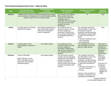
USER’S HANDBOOKD. Remote control unit installationThe ELT ADT 406² AF / AP can be remotely controlled by using a remote control panel installed in thecockpit of the aircraft.The maximum length of this link is 200 meters and requires no grounded cable. The link requires 4 wires.The following simplified diagram shows the wiring between the ELT ADT 406² AF / AP and its peripherals :– The Remote Control Panel (in cockpit) identified as "RCP",– the external antenna noted as "EA",– the back up antenna noted as "BA".The EA is connected to the ELT ADT 406² AF / AP BNC female connector (5).The BA is connected to the ELT ADT 406² AF / AP TNC female connector (1).The RCP is connected to the ELT ADT 406² AF / AP high density 15 pins female Sub-D connector (3).ELTA recommend to use P/N 28676 (or Type 8525-16R 14SN- or equivalent) to match RCP connector. Seedrawing 05E66081 presented in Appendix A page 10 for details.A three position guarded switch (2) controls the ELT ADT 406² AF / AP.A red indicator (4) displays the ELT ADT 406² AF / AP state.4 wires(not supplied)ELT HD 15pt RCPCONNECTOR CONNECTORON / ARMED1EELT ACTIVATED5CTEST / RESET7DV BATT (HI)13F02N64070 recommendedADT 406² AF / AP Beacon Installation – Wiring Diagram Figure 7Page 27Oct 11/07
USER’S HANDBOOKE. Installation and configuration of the beacon (Ref. Fig. 7)CAUTION : TO BE OPERATIONAL, THE BEACON SHALL BE IN "ARMED" POSITION ONCE IT HASBEEN CORRECTLY INSTALLED.Connect the antenna cable to the EXT. ANT. connector.Connect the back up antenna to ELT.Switch the Remote Control ON/ARMED lockable toggle switch to "ARMED" on remote control panel.Connect the remote control unit cable to the REMOTE CONTROL connector on ELT and lock it.Connect the remote control unit cable rear of the remote control panel and lock it.Switch the Beacon ARMED/OFF/ON lockable toggle switch to ARMED (pull and slide), the system is readyfor use.CAUTION : AS SOON AS THE BEACON IS IN ARMED IT CAN BE AUTOMATICALLY ACTIVATED BY THEINTERNAL G-SWITCH.Page 28Oct 11/07
USER’S HANDBOOK5. UTILIZATION OF THE ELT ADT 406² AF / AP (Ref. Fig. 8)CAUTION : IN THE EVENT OF UNTIMELY BEACON ACTIVATION, SHUTDOWN THE BEACON ANDINFORM THE CLOSEST SEARCH AND RESCUE (SAR) OR AIRPORT CONTROL TOWERIMMEDIATELY.The ELT ADT 406² can be activated in two modes :– automatic when the acceleration sensor is triggered,– manual.A. Automatic activationThe acceleration sensor has detected an impact sufficient to trigger it. The indicator light (8) and the auralindicator indicate beacon activation.Otherwise do not do anything and leave the beacon in operation until the rescue team arrives.Upon automatic activation the ELT enter directly in a waiting condition for about 30s (self test is notperformed). This state is displayed by a 2s slow rate blinking on indicator light (8) 1.75s ON, 0.25s OFF.WARNING : In case of false activation the operator shall shut down the ELT as described in C. Afterthis delay the ELT will transmit actual distress signals on the three availables distress frequencies.B. Manual activationThere are two cases in which a distress signal may be triggered manually :– the acceleration sensor (G.switch) has not been triggered but a distress signal must be sent (injuredpassengers, aircraft out of operation .),– the aircraft is on the ground and must be evacuated.(1)First case, from the Remote ControlRaise the safety cover (guard) on the remote control unit and place the switch in the ON position (leverupwards).An automatic self-test sequence is performed (see §D Beacon Self Test).Then the indicator light (8) and the aural indicator indicate beacon activation. This signal is permanentlydisplayed on the Remote Control LED.Do not do anything and leave the beacon in operation until the rescue team arrives.After about 30s of waiting condition, the beacon will transmit the three actual distress frequencies 121.5243-406 MHz.(2)Second case, from the beaconPlace the beacon switch (9) in the ON position (pull and slide).An automatic self-test sequence is performed (see §D Beacon Self Test).Page 29Oct 11/07
USER’S HANDBOOKThen the beacon enter in a waiting condition for about 30s. This state is displayed by flashing on indicatorlight (8) 1.75 s ON, 0.25 s OFF. This delay will avoid unwanted activation (false manoeuvre).Then the indicator light (8) and the aural indicator indicate beacon activation. The actual distress signalson 121.5-243-406 MHz are transmitted.This state is displayed by a quick 1s blinking on indicator light : 0.25 s ON, 0.75 s OFF.C. Beacon shutdownIn the event of a false manoeuvre or untimely operation, shutdown the beacon.The beacon is shutdown by pressing the RESET/TEST pushbutton on the remote control unit. This controlis not active during the self test sequence or if the ON/ARMED switch is in ON position.NOTE : Stopping distress signal transmission by means of the remote control unit does not switch thebeacon OFF. It is restored in ARMED mode.Acknowledgment of the control is displayed by 2 short blinks on beacon LED, beacon buzzer and onRemote Control Unit display.CAUTION : THE BEACON MUST BE SHUTDOWN BEFORE ANY MAINTENANCE OPERATIONS AREPERFORMED.THE BEACON MUST BE COMPLETELY SHUTDOWN BEFORE IT IS REMOVED AND IT'SARMED/OFF/ON TOGGLE SWITCH SHALL BE IN OFF POSITION.CAUTION : THE BEACON MUST NOT BE SHUTDOWN BEFORE THE END OF THE SELF TESTREPORT BY THE BEACON TOGGLE SWITCH. IT MAY RESULT IN A FALSE ELTACTIVATION DISPLAY ON THE REMOTE CONTROL UNIT.Page 30Oct 11/07
USER’S HANDBOOKD. Beacon self-testCAUTION : THE SELF-TEST SHALL BE PERFORMED WITHIN THE FIRST 5.MN OF ANY HOURBECAUSE THE ELT IS SENDING 121.5 MHZ SIGNAL FOR 1 S DURING THIS PROCESS(LIM
5. UTILIZATION OF THE ELT ADT 406² AF / AP 29 A. Automatic activation 29 B. Manual activation 29 C. Beacon shutdown 30 D. Beacon self-test 31 6. MAINTENANCE OF THE ELT ADT 406² AF / AP 33 A. Beacon self-test 33 B. Maintenance periodicity table 33 C. Battery replacement 34 D. Battery discarding 34