Transcription
Sodium Hydroxide (Activator of Sodium Persulfate)1. Submitted by Gary Cronk, JAG Consulting Group, Inc.2. Sodium hydroxide is commonly called caustic or caustic soda. It is used to raisethe pH of soil and water to act as an activator of sodium persulfate. In a watersolution, sodium hydroxide dissociates into sodium ions and hydroxide ions.3. MSDS - See attached file4. Number of Field Applications: 500 (estimated)5. Case Studies - See attached files6. Technical Summary: Sodium hydroxide is used as a high pH activator of sodiumpersufate. Sodium hydroxide is most commonly used in the field at aconcentration of 25%. Hydroxide is normally delivered by Tanker Trucks (3,000gal) or in totes (330 gal).When added to groundwater, sodium hydroxide will cause the pH of thesurrounding treatment area to increase to over 10. 5 pH units. A bench scale soilbuffering test should be performed in the laboratory to determine the quantity ofcaustic required to raise the pH to 10.5 units and to maintain that pH for up to 4hours. A properly designed buffering test will determine the soil bufferingcapacity in units of grams of NaOH per kilogram of soil. Soil buffering capacitycan vary greatly between sites (over 10 fold).Immediately after injection, sodium levels will increase by approximately 20%over baseline levels within the radius of influence. Sodium ions are quicklydiluted and dispersed by groundwater flow until the effects are no longerdetectable.Hydroxide ions will cause an immediate increase of pH that lasts about 30 days.At properly designed sites, the pH will typically return to normal within 30 to 60days. The natural soil buffering capacity slowly neutralizes the high pH conditionsand restores the groundwater to a neutral pH.Sodium hydroxide is highly corrosive and must be handled with establishedsafety precautions. Sodium hydroxide can cause serious burns to the skin, eyes,and lungs, so use of proper PPE is critical. A full face respirator and chemicalresistant clothing and gloves are required when handling caustic.
Evaluation of Sodium Hydroxidefor Inclusion in theGeneral WDR PermitBy: Gary Cronk, P.E.JAG ConsultingCltiGGroup, IInc.May 15, 2013
Physical Description of Sodium Hydroxide Simple molecular structure: NaOH Liquid solution also known as Caustic Soda or Caustic Used to raise the pH of groundwater (to 10.5 units) for theeffective activation of sodium persulfate Sodium hydroxide is most commonly used in the field at aconcentration of 25%.
Bench Testing to Ensure Effectiveness Soil buffering test should be performed initially Determines the amount of hydroxide required to raise andmaintain the pH over 10.5 units A properly designed test will determine the soil bufferingcapacitypy in units of ggrams NaOH pper kilogramgof soil Soil buffering capacity can vary greatly between sites. A Treatability Test should be performed to evaluate VOCdestruction at various doses.
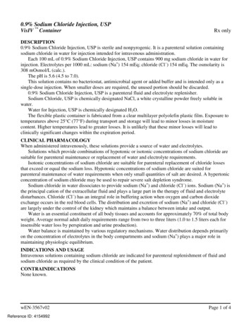
Impact on Water Quality NaOH in water disassociates into sodium ions and hydroxideions Sodium levels may increase by approximately 20%within the radius of influence Sodium ions are diluted and dispersed by groundwater flowuntil the effects are no longer detectable Hydroxideyions will cause an immediate increase of pHpthat lasts about 30 days At properly designed sites, the pH will typically return tonormal within 30 to 60 days Soil buffering capacity slowly neutralizes the alkalineconditions and restores the site to a normal pH
pH Levels in Monitoring Well MW-6MW 6141210pH (unitss)86420012345Days Since ISCO Injections68910
Minimize Health & Safety Issues Safe handling of sodium hydroxide requires closeadherence to established safety precautions. Sodium hydroxideycan cause serious burns to skin and lungsgso use of proper PPE is critical. Dermal and respiratory are the primary routes ofexposure for caustic Chemical delivered by Tanker Trucks (3(3,000000 gal) or by Totes(300 gal)
Additional Health & Safety For safety reasons, never use 50% hydroxide. Do not mix sodium hydroxide with persulfate. Always keep hydroxide selfcontained within storage tank, pumps and hoses Secondary containment should be provided for the sodium hydroxide storage tankand the persulfate mixing tank by placement of a wood berm (6-inches high)surrounding the tanks and then covering the berm with plastic sheeting. A rubber mat should be used to cover the nearby storm drain inlets and sand bagscan used to control flow direction. The local Fire Department (HazMat Unit) should be notified (as a courtesy)regarding the chemical storage and operations being performed at the facility in theevent of an uncontrolled chemical release. For safety reasons, always use an experienced injection contractor
Case Study No. 1 ‐ Circuit Board ManufacturerNNewportt Beach,B h CA Injected 5,600 gallons of 25% hydroxide and 3,100 gallonsoff persulfatelf t intoi t 6 iinjectionj ti wellsll Caustic delivered via tanker truck and stored in a3,000 ggallon tank ((double walled).) Extremely elevated levels of chlorinated VOCs werepresent at the site. In one monitoring well in the source zonezone, attained 99%destruction of TCE, 96% destruction of 1,1-DCE, 78%reduction of cis-1,2-DCE, 83% reduction of toluene, and68% reductiond ti off 11,4-dioxane4 diafterft 6 monthsth offmonitoring.g well showed nearlyy no changeg However, another monitoringafter 6 months.
Case Study No. 1 - Circuit Board ManufacturerNewport BeachBeach, CA
Case Study No. 2. Sun City, CA(former gas station site) Injected 3,300 gallons of 25% hydroxide and 1,700 gallons ofpersulfate into 8 injection wells Worked at night to minimize impact on retail business(W l(Walgreensstore)t ) Attained 90% to 95% destruction of TPH gas in threemonitoring wells after 4 months AttainedAttained 60% to 99% destruction of benzene in threemonitoring wells after 4 months.
Case Study No. 2. Sun City, CA((former ggas station site))
Case Study No. 3 Chicago, IL((Automotivei Chemicalsh i l site)i ) Soil treatment project only (groundwater treatment notrequired)i d) Injected 6,300 gallons of hydroxide and 7,800 gallons ofpersulfate into 12 vadose/GW zone injectionpjwells andan infiltration gallery (including horizontal wells underbuilding). Attained 99% destruction of PCEPCE, 99% destruction ofmethylene chloride, and 73% to 99% destruction ofTCE in soil samples. TheTh ISCO injectionsi j tiattainedtt i d theth soilil cleanuplcriteriait iestablished by the State of Illinois EPA and “No FurtherAction” was ggranted for Area #1 and Area #2 in 2009.
Case Study No. 3 Chicago, IL(Automotive Chemicals site)
Case Study No. 4. Huntington Harbor, CA(gas station site) Injected 2,900 gallons of hydroxide and 1,500 gallons ofpersulfate into 3 wells BTEX levels reduced by 82% to 100% and TPH gas reducedb 81%by
Case Study No. 5. Milpitas, CA(gas station site))(g Injected 2,300 gallons of hydroxide and 4,500 gallons ofpersulfate into 16 direct pppush boringsg Attained moderate results, up to 74% destruction of TPH asgas, 85% reduction of Toluene, 89% reduction ofxylenes and 76% reduction of ethylbenzene,xylenes,ethylbenzene and 29%reduction of benzene in one monitoring well. pH levels did not increase to above 10 pH level and inhibitedth activationtheti ti off persulfate.lf t After further Bench Scale Testing, it was determined this sitehad veryy highg Soil Bufferingg Capacitypy ((7.16 g NaOH/kggsoil) which was causing problems with proper activationof persulfate.
Case Study No. 5. Milpitas, CA
CASE STUDY COMPARISON OF MULTIPLE ACTIVATIONMETHODS FOR SODIUM PERSULFATE ISCO TREATMENTGary Cronk, P.E. (JAG Consulting Group)Presentation at the Battelle 6th International Conference on Remediation of Chlorinatedand Recalcitrant Compounds, May 19-22, 2008ABSTRACT: Several methods are available for activating sodium persulfate, includinghydrogen peroxide, ferrous iron or chelated iron, alkaline conditions (high pH), and heat.This paper discusses in-situ chemical oxidation (ISCO) case studies (both full scale andpilot studies) which were designed and implemented using varying methods foractivating persulfate. A total of six case studies are discussed with regards to selection ofactivator, reduction in contaminant levels, and site conditions affecting the ISCOtreatments.To obtain optimal contaminant destruction and efficiency, the proper activation methodfor persulfate must be selected. Selection of the activation method is dependent upon boththe contaminant(s) of concern and the site conditions. As a general rule of thumb, FMCCorporation has stated the most aggressive means of persulfate activation is by use ofhigh pH and/or hydrogen peroxide. However, there are certain site conditions wherethese activators might not be the best choice. For shallow groundwater UST sites, thehigh pH or peroxide might cause corrosion or damage to utilities and metal objects thatmay come into contact with the activator or the persulfate. In addition, hydrogen peroxideoften reacts very aggressively in the subsurface and care must be taken to adequately ventoff-gas production and control the reaction so that peroxide does not come to the surface.FMC does not recommend iron activation for destruction of gasoline range and dieselrange organics, although it is effective on MTBE, TBA, BTEX, and other hydrocarbons.In addition, iron activation is not recommended for treatment of vinyl chloride,methylene chloride, carbon tetrachloride, TCA or DCA.The six ISCO case studies were all sites located in California. The following is abreakdown of the activators used on the sites: Hydrogen peroxide activation – 2 sitesHigh pH activation – 2 sitesIron activation - 2 sitesGood to excellent contaminant reductions (generally exceeding 85% reduction) wereachieved in all these case studies, due in large part to the matching of site conditions tothe best activation method.INTRODUCTIONIn recent years, sodium persulfate has become a commonly used oxidant for manycontaminated groundwater sites. Persulfate is a strong and versatile oxidant capable of
treating a wide spectrum of organic contaminants. The activation of sodium persulfatecan be achieved by any of the following methods: Hydrogen PeroxideFerrous Iron or Chelated IronHigh pHHeatOnce the persulfate is activated by one of the above methods, it results in the formationof sulfate free radicals (SO4- ) as represented in Equations 1 through 4 below. The sulfateradicals can also produce hydroxyl radicals (see Equation 2). Free radicals are molecularfragments that have an unpaired electron causing them to be strong oxidizing agents andare known to rapidly oxidize many VOCs. In addition to its oxidizing strength, persulfateand sulfate radical oxidation has several advantages over other oxidants. First, it iskinetically fast. Second, the sulfate radical is more stable than the hydroxyl radical andthus able to transport (diffuse) greater distances and create a larger radius of treatment.Sulfate Radical Generation and Reactions:Initiation:NaS2O8 Activator 2SO4- Na(Generation of Sulfate Radicals (SO4- )Propagation: SO4 - H2O OH- HSO4(Generation of Hydroxyl Radicals (OH- )Termination: SO4- RH R HSO4OH- RH R H2O(Equation 1)(Equation 2)(Equation 3)(Equation 4)Where: RH represents an organic compound;R represents oxidized organic compoundSoil oxidant demand and metals also contribute to oxidant consumption.Note: Free radical chemistry is not necessarily stoichiometric or straightforward.SELECTION OF THE RIGHT ACTIVATORTo obtain optimal contaminant destruction and efficiency, the right activation methodmust be selected. Selection of the activation method is dependent upon both thecontaminant of concern(s) and the site conditions. For example, for cleanup of gasolineor diesel contaminated UST sites, the best activator would be high pH or hydrogenperoxide. Heat could also be used, but generating or obtaining a source of heat is oftencostly (unless the site is already producing steam or another source of heat). FMCCorporation does not recommend iron activation for destruction of gasoline range anddiesel range organics, although it is effective on MTBE, TBA, BTEX, and otherhydrocarbons.
For mixed solvent plumes containing chlorinated ethenes, such as TCE, PCE, DCE, andvinyl chloride, any of the four activation methods would work well. However, if the sitecontains high levels of vinyl chloride, methylene chloride, carbon tetrachloride, TCA orDCA, activation by iron activation is not recommended. In this situation, high pH orhydrogen peroxide would be the activator of choice. 1,4-dioxane can be treated byactivation by iron, high pH, or peroxide.As a general rule of thumb, FMC has stated the most aggressive means of persulfateactivation is by use of hydrogen peroxide and/or high pH. However, there are certain siteconditions where these activators might not be the best choice. For shallow groundwaterUST sites, the high pH or peroxide might cause accelerated corrosion of utilities andmetal objects that it comes into contact with. In addition, hydrogen peroxide often reactsaggressively in the subsurface and care must be taken to adequately vent off-gasproduction and to minimize peroxide coming to the surface. Sensitive sites where thesurfacing of hydrogen peroxide could cause issues for the owner’s business operationswould not be good candidates for peroxide.Site 1. Hydrogen Peroxide ActivationSite 1 is an industrial site located in Ranch Dominguez, CA (Los Angeles County).Hydrogen peroxide activation was selected for treatment of this methylene chlorideDNAPL site. This activation technique, which incorporates combined oxidizing power ofperoxide and persulfate along with heat given off by the Fenton’s reaction, was selectedbecause of the recalcitrant nature of methylene chloride and the difficult site conditions.This project was extremely difficult because most of the contaminant plume was under anactive industrial building and the contaminants were isolated within a clayey formation ata depth of 40 to 50 feet. A total of 16 of the 23 injection wells were located inside thebuilding with several slant wells installed in sensitive areas where the owner’s equipmentcould not be re-located.Results – Site 1.Pre-treatment methylene chloride levels over 15,000 µg/l were reduced to levels less than50 µg/l within 258 days. “Surfacing” of hydrogen peroxide occurred at this site and offgas venting issues caused some minor damage to the asphalt pavement. Closure of thissite has recently been granted by the Los Angeles Regional Water Quality Control Board.
FIGURE 1. Reductions in methylene chloride following persulfate 00 Day1,0000Concentration(ug/l)10,000Site 2. Hydrogen Peroxide ActivationSite 2 is an industrial site located in Huntington Beach, CA (Orange County). Hydrogenperoxide activation was selected for the 8 well pilot scale treatment of 1,4-dioxane andchlorinated solvents, due to the extremely elevated levels of these recalcitrantcontaminants. Depth to groundwater was approximately 12 feet.Results – Site 2.After 231 days, the 1,4-dioxane levels were reduced substantially, with levels as high as260,000 µg/l being reduced to 21,000 µg/l (92% reduction). “Surfacing” of peroxide didoccur at this site. As a result of the highly successful pilot test, further ISCO treatment ofthe site is being planned.FIGURE 2. Reductions in 1,4-dioxane following persulfate ell DE-1Well MW-9Well 0,00018,00012,0000Day -3012,0005,200Day 3513,0003,800Day 6510,000Day 956,0002,500Day 12521,0001,300120Day 231
Site 3. High pH ActivationSite 3 is an industrial site located in Santa Ana, CA. Alkaline activation of sodiumpersulfate using 25% sodium hydroxide was used for the pilot scale treatment of a mixedchlorinated solvent plume. Two injections wells were utilized. Depth to groundwater wasapproximately 25 feet.Results – Site 3.Significant reductions were observed within 30 days for TCE (95%), 1,1-DCE (99%),and other contaminants, but a moderate rebound effect was observed after 45 days of theinjection. The rebound effect was believed to be due to release of adsorbed contaminantsfrom the soil. In addition, continued migration of contaminants from the source arealikely masked the results in the treatment area, which was located downgradient of thesource area.FIGURE 3. Reductions in 1,1-DCE Following Persulfate Treatment.7000600059001,1-DCE (ug/L)500040003900Well 1A3000Well 1BWell 22000120012001000500010.39-221181402.529520163Days Following ISCOSite 4. High pH ActivationSite 4 is an active gas station site located in Huntington Harbor, CA. High pH activationof persulfate using 25% sodium hydroxide was selected for this site because of itstreatment effectiveness on gasoline range hydrocarbons. Depth to groundwater was at 30feet bgs, so no interference with shallow utilities was anticipated. Three existingmonitoring wells surrounding the UST source area were used as injections wells for thistreatment project.
FIGURE 4. Mixing of persulfate solution.Results – Site 4.After 77 days, the TPH gas levels were reduced substantially, with levels as high as 860µg/l reduced to 160 µg/l and BTEX levels reduced by 82% to 100%. This site is early inthe monitoring phase and additional results over the next several months will likelycontinue to show reductions in contaminant levels.FIGURE 5. Reductions in TPH as gas following persulfate treatment.3,0002,5002,500TPHGas Concentrations 77DaysSITE 5. Ferrous Sulfate ActivationSite 5 is an industrial site located in La Mirada, CA (Los Angeles County). Ferrous ironwas selected to activate sodium persulfate for treatment of a small but highlyconcentrated benzene plume. Three injection wells were utilized. Depth to groundwaterwas approximately 80 feet.
FIGURE 6. Mixing of ferrous sulfate into solution.Results – Site 5.Reduction of benzene levels from 2,900 µg/l to 160 µg/l was achieved after 253 days ofthe persulfate injection. A mild rebound effect occurred at this site after 30-60 days, dueprimarily to a rising water table and cross contamination from the deep vadose zone.Following removal of the deep vadose zone contamination using soil vapor extraction,the benzene levels did not rebound again and have remained below 160 µg/l. Closure ofthe benzene plume at this site is currently being pursued with the Los Angeles RWQCB.FIGURE 7. Benzene reductions following persulfate treatment (iron ell MW-4Well ay500Site 6. Chelated Iron ActivationSite 6 is an industrial site located in La Mirada, CA (same site as Case Study 5). Chelatediron (EDTA) was selected to activate sodium persulfate for treatment of a TCE and 1,4Dioxane plume. A three well injection was recently performed using existing monitoringwells. Depth to groundwater is approximately 80 feet.
Results – Site 6Reduction of TCE levels from 290 µg/l to 50 µg/l was achieved after 70 days of the ironactivated persulfate injection.FIGURE 8. TCE reductions following persulfate treatment (iron 500Day -41Day 7Day 14Day 21Day 28Day 70REFERENCESFMC Corporation, 2008. “Activation Know How”, located on the FMC website.FMC Corporation, 2008. Table of Klozur Activation Chemistries, located on the FMCWebsite.
Controlled Vadose Zone Saturation and Remediation (CVSR)Using Chemical OxidationGary Cronk, P.E. (JAG Consulting Group, Inc.)Stephen Koenigsberg, Barbara Coughlin, Mark Traversand Dave Schlott (ENVIRON International Corporation)Presentation at the Battelle 7th International Conference on Remediation of Chlorinatedand Recalcitrant Compounds, May 24-27, 2010AbstractControlled Vadose Zone Saturation and Remediation (CVSR) is essentially a longoverdue advancement of standard in-situ treatment methods that have been traditionallyused in the saturated zone. Unsaturated zone treatment technologies are not new, butthey normally revolve around mechanical operations such as soil vapor extraction (SVE).While the cost of CVSR is comparable to SVE, it can generally be performed within amuch shorter timeframe (6 months). To our knowledge, this is only the second publishedreport combining CVSR with in-situ chemical oxidation (ISCO).CVSR technology was successfully applied to an active industrial site in Illinois.Alkaline activated sodium persulfate using sodium hydroxide was used to treat theshallow soils to a depth of 15 feet. The vadose zone soils were contaminated with avariety of VOC constituents including PCE, TCE, methylene chloride, ethylbenzene,toluene, and total xylenes. Prior to the field injections, a soil buffering test was performedin the laboratory in order to determine the amount of sodium hydroxide needed to raisethe pH of the soil to above 10.5 units and maintain it for five days.Because chemical oxidation relies on diffusion of oxidants in an aqueous medium, thevadose zone soils were saturated using a combination of vertical injection wells, aninfiltration gallery, and horizontal injection wells installed beneath two small buildings.The infiltration gallery and the horizontal wells were initially used to percolate water intothe vadose zone to achieve saturation. The vertical and horizontal wells were then usedto inject the hydroxide and oxidant. A total of 12 vertical injection wells where installedin two treatment areas along with the infiltration gallery. Due to the presence of lowpermeability silts and clays, each vertical injection well had an estimated radius ofinfluence of 10 feet. Approximately 4,700 gallons of sodium hydroxide (25%concentration) and 11,500 pounds of sodium persulfate were injected over a 27 dayperiod in November and December of 2008. A second injection of activated persulfatewas performed in Area 1 in August 2009.The concentrations of the compounds of concern, PCE, TCE, methylene chloride,ethylbenzene, toluene, and total xylenes, all decreased from 88% to 99% within 180 daysafter treatment. The ISCO injections attained the site-specific soil cleanup criteria, inconjunction with an engineered barrier, established by the State of Illinois EPA.Project Site DescriptionThe project site is located in a suburb located just north of Chicago, Illinois. The site wasimpacted by various volatile organic constituents, including toluene, ethylbenzene, total
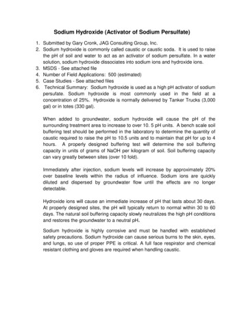
Page 2 of 8xylenes, acetone, methylene chloride, PCE, and TCE. Two areas of concern exist at thesite; the Filling Room (Area 1) and the Fill Pipe area (Area 2). The Filling Room Areameasured approximately 3,850 ft2 and the Fill Pipe Area measured 1,200 ft2. Depth togroundwater beneath the site is approximately 5 feet below ground surface (bgs) beneaththe Filling Room Area and 15-16 feet bgs in the Fill Pipe Area. Soils were predominantlysilty clays and clayey silts with some sandy stringers. No visual LNAPL or DNAPL waspresent in the monitoring wells prior to the ISCO treatment, although the highconcentrations in the soil and groundwater (over 1% saturation level) indicate thatLNAPL or DNAPL could be present at the site.The vadose zone soils in the two areas of concern were the primary target forremediation. At the Filling Room Area (Area 1), the target treatment zone was from 2feet to 8 feet bgs. At the Fill Pipe Area (Area 2), the target treatment zone was from 2feet to 15 feet bgsProject ObjectivesThe objective of the ISCO injection was to reduce the soil concentrations of VOCs at theSite to concentrations below site-specific Tier 2 Soil Remediation Objectives establishedby the State of Illinois EPA. To accomplish the ISCO treatment, the vadose zone soilswere initially saturated with water using an infiltration gallery and horizontal injectionwells in order to create an aqueous media and allow for dispersion of oxidants.Infiltration Gallery and Injection Well ConstructionJAG Consulting Group designed and installed an infiltration gallery in Areas 1 and 2 tosaturate the vadose zone and to provide an aqueous medium for dispersion and diffusionof the persulfate radicals and to provide oxidant contact with all the soil particles andVOCs within the vadose zone. In addition, eight horizontal wells were drilled under thetwo small buildings located in Area 1 in order to treat VOC contamination under thebuildings (see Figure 1). The horizontal borings were drilled with a horizontal boringmachine, as shown in Figure 2.ENVIRON installed eleven new vertical injection wells, designated IW-1 to IW-11,within the two treatment areas on November 5 to 7, 2008 (see Figure 1). Eight of thenew injection wells in Area 1 were screened from approximately 3 feet to 8 feet bgs,while the remaining three injection wells in Area 2 were screened from 3 feet to 15 feetbgs. The injection wells were constructed of 2-inch schedule 40 PVC casing and screen.At ground surface, each injection well was completed with a concrete pad and a flushmounted steel well box. Based on the low permeability silts and clays, each injectionwell had an estimated radius of influence of 10 feet. Following installation, the injectionwells were developed by ENVIRON by surging the sand pack and removal of water untilclear water was produced.
Page 3 of 8Figure 2. Drilling of Horizontal Wells (Area 1)
Page 4 of 8Bench Scale TestingA soil buffering test in the laboratory was performed and confirmed that the soils beneaththe site are highly buffered. The buffering test was performed by determining the amountof sodium hydroxide required to raise and maintain the pH of the soil above 10.5 units fora period of five days. This provided a scale-up quantity of sodium hydroxide that wouldbe required in the field.A laboratory bench scale soil oxidant demand (SOD) test was also performed. Theresults indicate SOD values (3.0 to 4.5 g/kg) to be in the normal to slightly elevatedrange. Contributors to SOD include naturally occurring organics in the soil, the presenceof reduced metals, and high alkalinity and total dissolved solid (TDS) levels which cancause scavenging of oxidants. The SOD results were interpreted to mean that some slightamount of interference with oxidation may occur and additional injection events ofpersulfate may be required to attain the low cleanup objectives for the soil.Injection EventsThe first injection event occurred from November 18 to December 15, 2008 (27 dayperiod). Approximately 4,700 gallons of sodium hydroxide (25%) and 11,500 pounds ofsodium persulfate (5,320 gallons at 24%) were injected into the wells over this period.Freezing temperatures and snowfall caused many delays in early December 2008 whichextended the injection period. For safety reasons, no excess pressure (less than 20 psi)was applied during the injections (only gravity feed pressures were used).During the ISCO injections, ground surfacing of chemicals (daylighting) was observedoften and was immediately controlled by turning off the flow valve leading to the nearestinjection well. Neutralization of the caustic sodium hydroxide that bubbled to the surfacewas accomplished by use of a mild muriatic acid (HCl) solution, while the persulfate wasneutralized using a mild solution of sodium bisulfite (reducing agent). Field personnelinspected the injection areas and observed no visible signs of subsurface degradation,subsidence, or bulging of pavement.The second injection event was only performed in Area 1 and occurred from August 4 toAugust 16, 2009 (12 day period). A total of 2,600 gallons of sodium hydroxide wasinjected into Area 1 and 2,475 gallons of sodium persulfate (at 24% solution) wasinjected during this injection event.Air Quality Monitoring DataTo protect the health and safety of field personnel, facility employees, and the publicduring field activities, and to monitor for the potential migration of subsurface gasvapors, JAG Consulting Group implemented an air monitoring program. The emissionsfrom each injection well and various points in and around the work area were monitoredperiodically throughout each workday with a four gas air quality meter that monitored foroxygen, carbon dioxide, carbon monoxide, and lower explosive limit.
Page 5 of 8During the sodium hydroxide injections, (Days 1 through 6) only minor fluctuations inoxygen levels were detected (see Figure 3.). However, during the persulfate injectionsstarting on Day 9 and 10, an immediate increase in oxygen level up to 23% to 29% wasdetected in the injection wells and generally stayed elevated throughout the ISCOinjection. This observation was expected, as persulfate is known to release smallquantities of oxygen gas as it degrades VOCs.Carbon dioxide (CO2) levels were observed to generally remain at moderate levels(200 ppm to 500 ppm) for the first 11 days of injections. Starting on Day 12, the carbondioxide levels increased dramatically to levels above 4,000 ppm in injection wells IW-3and IW-4 (see Figure 4). Carbon dioxide gas is formed as a breakdown product ashydrocarbon bonds are destroyed by the persulfate.Carbon monoxide (CO) levels generally remained at low levels (less than 200 ppm) forthe first 6 to 8 days. Starting on Day 8 and 9, the carbon monoxide levels increased tolevels above 800 ppm in the injection wells (see Figure 5). Carbon monoxide gas is alsoformed as a breakdown product as hydrocarbon bonds are destroyed.
Page 6 of 8The lower explosive limit (LEL) levels were generally non-detectable during most daysof ISCO injections. The only detected readings were 4% LEL on Day 13 in injectionwell IW3, 4% LEL on Days
Always keep hydroxide self contained within storage tank, pumps and hoses Secondary containment should be provided for the sodium hydroxide storage tankSecondary containment should be provided for the sodium hydroxide storage tank and the persulfate mixing tank by placement of a wood berm (6-inches high)