Transcription
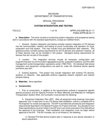
12SP-826I-03MICHIGANDEPARTMENT OF TRANSPORTATIONSPECIAL PROVISIONFORSYSTEM INTEGRATION AND TESTINGITS:CLC1 of 19APPR:JVG:DBP:06-21-17FHWA:APPR:08-02-17a. Description. This work consists of conducting system integration and acceptance testingwork in accordance with the standard specifications, except as modified herein.1. General. System integration and testing includes network integration of ITS devicesinto the communication network and testing to prove functionality and operation for local,subsystem and final system. This may include trunk and distribution fiber networks. Thisspecial provision contains testing requirements for all ITS devices and networks; however, allof these devices may not be included in this project. Disregard testing requirements fordevices that are not part of this project.2. Location.The integration services include all necessary configuration andprogramming work at communication aggregations points, subsystem locations, and the trafficmanagement center/transportation operations center (TMC/TOC). All individual field deviceintegration and equipment configurations are paid for under the individual device specialprovisions pay item.3. Existing Systems. This project may include integration with existing ITS devices,systems, or networks. See applicable sections regarding network migration and networkpre/post testing.b. Materials. None specified.c. Construction.1. Prior to construction, in addition to the requirements outlined in equipment specificspecial provisions and the Special Provision for Basic Methods and Materials for IntelligentTransportation System Work, the Contractor must provide the following:A. Equipment Integration Plan (EIP). After all equipment shop drawings have beenapproved, and 14 days prior to any ITS device field installation, submit a complete EIP tothe Engineer for review and approval. The EIP must follow the procedures and integrationrequirements described in the Special Provision for Project Overview. Any deviations fromthese specifications must be noted in the EIP and must not be executed in the field withoutthe approval of the Engineer. Field installation and integration must not begin beforeapproval of the EIP. The EIP includes, but is not limited to, the following:(1) Revised ITS field device location plan in response to any device relocation orlayout adjustment.
ITS:CLC2 of 1912SP-826I-0306-21-17(2) Revised ITS field device interconnection and wiring layout plans in responseto any construction field changes.(3) Detailed step-by-step integration procedures for each local and TMC/TOCintegration. Typical site integrations can be grouped in one integration procedure byapproval of the Engineer.(4) Typical devices interconnect diagrams for local, Hub/Node, and TMC/TOClocations. All device interconnect diagrams must be generated in Visio, CAD, orMicrostation and must clearly identify equipment model numbers and cable types.(5) Network Integration details, including but not limited to the following:(a) Overall system network diagram, including full logical network and InternetProtocol (IP) configuration details for all devices in a system diagram and tabulatedformats.(b) Bandwidth and traffic flow analysis for all network layers links includinganticipated typical traffic flows.(c) Network segmentation and virtual local area network (VLAN) configuration.(d) Port assignments for all network and ITS devices.(e) Provide proposed routing protocol and scheme including details of themethod of operations and failover criteria, failover settings and routing costs.Include at a minimum:(i) IP Unicast Routing;(ii) IP Multicasting Routing;(iii) Internet Group Management Protocol (IGMP); and(iv) Constraint methods for multicast packet flooding.(f) Provide a planned method of testing performance. Include at a minimum:(i) Performance criteria description, proposed measurements, andmethods of measurement;(ii) Acceptance threshold and references for the values;(iii) Network loading, 20, 50 and 90 percent full capacity at access,distribution and trunk layer; and,(iv) Measurement tools.(g) Proposed configurations of Managed Field Ethernet Switches.
ITS:CLC3 of 1912SP-826I-0306-21-17(h) Proposed coordination steps with the ITS Maintenance Contractor to havefield switches integrated into MDOT’s Network Monitoring System (NMS).(6) Equipment programming/configurations for each ITS device type included inthe Bill of Materials (BOM) and as specified in the Special Provision for Basic Methodsand Materials for Intelligent Transportation System Work.(7) Advanced Traffic Management System (ATMS) Software Integration plan andproposed procedures.(a) Procure material compatible with the MDOT Statewide ATMS Software.(b) Confirmation testing and software integration into the ATMS will be paid forunder the Special Provision for Integration, Advanced Traffic Management SystemSoftware.(8) Fiber Network Integration plan. The fiber network integration portion of the EIPmust include, but is not limited to, the following:(a) Plan to test fiber optic cable prior to the connection into the Node switchesand provide comparison between the calculated and anticipated measured opticallink budgets, including adjustments for optical sensitivity.(b) Proposed coordination steps with the ITS Maintenance Contractor fornetwork integration into existing or proposed switches at Hub/Node and TMC/TOClocations including:(i) Back-end network configurations;(ii) Installation of fiber optic transceivers;(iii) Network termination and end-to-end connectivity establishment; and(iv) Port configuration including open shortest path first routing.(c) Proposed termination of the distribution network into patch panels at localITS cabinets as shown on the plans.(d) Proposed configuration of new field switches in ITS cabinets that arelogically nearest to the Node. Configuration for the ITS site next in the networkarchitecture can only continue if previous link communications chain has beenintegrated and communications verified.(9) Include a Network Migration Plan as part of the EIP if called for in the SpecialProvision for Project Overview. Submit a Network Migration Plan identifying theintended process for transitioning communications from the existing networkarchitecture to the proposed network architecture including, but not limited to:(a) A detailed action plan identifying each step in the installation and migrationactivities including testing.
ITS:CLC4 of 1912SP-826I-0306-21-17(i) Pre-Migration Testing. Test existing network and ITS device availabilitybefore network and device migration. Work with the ITS MaintenanceContractor for pre-testing. Ensure the results are used to compare pretestingto post test results. Propose expected changes in results in the AcceptanceTest Plan.(ii) Post Migration Testing. Ensure testing is completed in accordance withthe Acceptance Test Plan requirements.(b) A list of certified personnel performing the work at each location;(c) Contact information for the main point of contact during regular businesshours and emergencies;(d) Switch installation and configuration details;(e) A list of equipment to be removed;(f) A contingency plan for each activity identifying recovery process from eachsituation outlined in the migration plan;(g) An outline of downtime and risk mitigation strategies; and(h) Coordination for reintegrating existing devices into ATMS if the proposednetwork configuration utilizes a new addressing scheme.B. Acceptance Test Plan (ATP).(1) General Requirements.(a) If a system mock up is required, submit a complete ATP to the Engineer atleast 14 days prior to beginning the mock up. If a system mock up is not required,submit a complete ATP to the Engineer 14 days prior to installing any electronicdevices in the field.(b) The ATP must include individual test cases clearly showing passing criteriafor all ITS devices as applicable per project.(c) The ATP must include local, subsystem, and final system testing for all ITSdevices to be integrated on this project.(d) Failures during testing must be included in a report that documents thedefective unit or setting and the corrective action taken. Minor failures may beaddressed and retested at the Engineer’s discretion. Major failures, which wouldrequire additional work to multiple units and sites, may cause the Engineer to stoptesting until the issue has been resolved. No extension of time or additionalpayments will be given or made due to delays caused by failed acceptance testing.(e) The ATP forms as well as any supplemental documentation completedduring the testing are to be delivered to the Engineer upon system acceptance.
ITS:CLC12SP-826I-0306-21-175 of 19The forms must be signed by the Contractor as well as the Engineer orrepresentative.(2) ITS Local Device Assembly Test (LDAT). Before ITS sub-system tests (SST),conduct stand-alone tests of the equipment installed at each field site as approved bythe Engineer. The test must, at a minimum, exercise all stand-alone (non-network)functional operations of the field equipment with all of the equipment installed per theplans or as directed by the Engineer.(3) ITS Sub-System Test (SST). Conduct SST to verify a section of the overallITS system is functioning properly. Sub-system testing must be conducted at logicalnodes or aggregation points to verify both communications and device functionality.(4) ITS Final System Test (FST). FST is the last step in the ATP and serves asthe basis for system acceptance. The FST must be performed at the TMC/TOCfollowing completion of the SST. After the successful completion of the FST, the burnin period begins.(5) Testing Requirements. The list of ITS devices and testing requirementsidentified in Table 1 must be included in the ATP. Test procedures required for FiberOptic and Licensed Wireless Link Backhaul must be submitted as part of their ownspecial provision requirements.Table 1: List of ITS Devices Required for ATPITS DevicesTest Procedures RequiredITS CabinetSurveillance System AssemblyDynamic Message Sign (DMS)LDAT, SST, FSTLDAT, SST, FSTLDAT, SST, FSTMicrowave Vehicle Detection System (MVDS)Managed Field Ethernet Switches (MFES)Digital Video Encoder (DVE)Uninterruptible Power Supply (UPS)Unlicensed Wireless RadiosCellular Modems/Cable ModemsLDAT, SST, FSTLDATLDATLDAT, SST, FSTLDATLDAT, FSTEnvironmental Sensor Station (ESS) EquipmentIP Power Distribution UnitTower LightInfrared Illumination DeviceLane Control System (LCS)Dynamic Message Panel (DMP)LDAT, FSTLDAT, FSTLDATLDATLDAT, SST, FSTLDAT, SST, FSTFiber Optic Hardware AssemblyLDATFor each ITS device type, there must be a test case developed with pass/fail criteria.All functional requirements in the test case must pass during the witness testing togrant final acceptance. The sections below list all functional requirements per deviceto be included in each test case. During the review of the ATP report, the Engineer
ITS:CLC6 of 1912SP-826I-0306-21-17has the right to add or remove test case requirements, as applicable, to the projectand within the functional requirements shown in the special provisions.(a) ITS Cabinet.(i) LDAT.1) Visual inspection to check workmanship, confirm equipment hasbeen installed in accordance with approved layout drawings and equipmentshop drawings, and verify the cabinet field wiring matches the cabinetwiring diagram and interconnect drawings are stored in the cabinet.2) Verify proper operation of the Ground Fault Interrupter (GFI) outlet.3) Verify proper operation of the lights and vent fans.4) Verify all ITS devices are labeled as required with the device nameand IP address.5) Verify accuracy of the temperature and humidity reported by thecabinet monitoring system.6) Test door alarms locally.7) Verify network settings (i.e., IP address, subnet mask, andgateway).8) Demonstrate the cabinet monitor system can successfully use aSimple Network Management Protocol (SNMP) trap for dooropening/closing.(ii) SST. Verify communications to the SNMP card of the cabinetmonitoring system.(iii) FST.1) Test Alarm Conditions. Demonstrate the cabinet monitoring systemcan successfully use SNMP traps to alert a computer at the TMC/TOCabout an open door and a high temperature.2) Verify the ability of users in the TMC/TOC to determine thetemperature, humidity, and door status using a web browser.(b) Surveillance System Assembly.(i) LDAT. The following local field operational tests must be performed atthe camera assembly field site on each closed-circuit television (CCTV)camera. Provide a laptop computer testing the video and camera controlthrough software that supports National Transportation Communications forITS Protocol (NTCIP). After the camera assembly, including the camerahardware, DVE, power supply, and connecting cables, has been installed:
ITS:CLC7 of 1912SP-826I-0306-21-171) Verify physical construction has been completed as detailed in thecontract and herein.2) Inspect the quality and tightness of ground and surge protectorconnections.3) Verify the camera control address, as applicable.4) Verify the presence and quality of the video image via a videostreaming client on the laptop computer.5) Demonstrate camera sensitivity at low light levels meets thespecification.6) Verify title block information is correct.7) Exercise the pan, tilt, zoom (PTZ), focus - auto and manual, irisopening, and manual iris control selection; and the operation, low-pressurealarm (if present), preset positioning, and power on/off functions.8) Demonstrate pan/tilt speed and extent of movement meets thespecifications.(ii) SST. Verify communications to the surveillance system or DVE.(iii) FST. The following remote operational tests must be conducted at theTMC/TOC using NTCIP software.1) Verify the camera IP address and system name.2) Verify the presence and quality of the video image.3) Exercise the PTZ, focus, iris opening, and manual iris controlselection; and the operation, low-pressure alarm (if present), presetpositioning, and power on/off functions.(c) DMS.(i) LDAT. DMS LDAT must be conducted at each field location after theDMS has been installed and integrated into the system. The test cases, atminimum, must include inspection of the sign housing, power supply, andelectrical distribution; DMS controller; DMS Auxiliary Control Panel (ACP);Light-Emitting Diode (LED) display modules; temperature and light control; andsign failure conditions.1) DMS Controller.a) Verify a “local/remote” switch with an LED indicator that placesthe controller in local mode such that it can be controlled from the frontpanel interface instead of via the primary communication channel.
ITS:CLC8 of 1912SP-826I-0306-21-17b) Verify the reset switch to quickly restart the controller.c) LED “Active” indicator blinks when the controller is operating.d) Verify system status Liquid Crystal Display (LCD) displays timeand date.2) DMS ACP.a) Verify a “local/remote” switch with an LED indicator that placesthe controller in local mode such that it can be controlled from the frontpanel interface instead of via the primary communication channel.b) Reset switch to quickly restart the controller.c) LED “Active” indicator blinks when the controller is operating.d) Verify system status LCD displays time and date.3) LED Display Module.a) On command from either a remote computer or local laptoprunning the central control software, the sign controller must test theoperation of all LED pixels and determine whether their functionalstatus is “normal” or “stuck-off.” Run a diagnostic test to verify all the LED driver cards,power supply diagnostic cards, temperature sensor cards, fansensor card, and photo sensor are functioning properly. Verify Real-time DMS message posting. Verify static test message display. Verify flashing test message display. Verify a multipage test message display. Verify manual blanking of the display.4) Light Control (DMS Intensity Control).a) Verify from the DMS controller the option of selecting from aminimum of 100 LED intensity levels. LED intensity levels must beavailable in a range of 1 percent to 100 percent of the maximum displayintensity, and in increments of 1 percent.b) Not cause any flickering of the LED display matrix.
ITS:CLC9 of 1912SP-826I-0306-21-17c) Verify manual and automatic intensity control modes to be userselectable using the DMS control software, although the typical controlmode must be “automatic.”d) Verify manual intensity control from both local and remotelocations.5) Sign Failure Conditions.a) Verify that in the event of communication error between theDMS sign controller and the system control computer; the DMScontroller automatically blanks the sign.b) Verify that in the event of a power failure, the DMS controllerautomatically blanks the sign.c) All testing work, activity, and results must be documented andreported with their details to the Engineer.(ii) SST. Verify communications to the DMS controller.(iii) FST. The DMS FST must be conducted from the TMC/TOC using theATMS software. In the event the ATMS software is not capable of testing somerequired functional specifications of the DMS, then the DMS specificmanufacturer’s software can be used. Test the following requirementsremotely:1) LED display module as described in the LDAT.2) DMS intensity control as described in the LDAT.3) Sign failure conditions as described in the LDAT.(d) MVDS.(i) LDAT.1) Verify physical construction has been completed as specified in thecontract and herein.2) Verify network settings.3) Inspect the quality and tightness of ground connections.4) Using the manufacturer’s software, display lanes and verify lanesmatch actual field conditions.5) Verify speed, volume, and occupancy are within the requirementsof the MVDS special provision. The use of a calibrated Lidar gun isrequired for the speed test.
ITS:CLC10 of 1912SP-826I-0306-21-176) All testing work, activity, and results must be documented andreported with their details to the Engineer.(ii) SST. Verify communications to the MVDS.(iii) FST.1) Verify network interface device is receiving and transmitting datafrom the remote site to across the ITS network.2) Conduct FST from the head end ATMS software.(e) MFES.(i) LDAT.1) Verify physical connections are performed as specified in contract.2) Verify all LED indicators for link, activity, and power are functioning.3) Verify these configuration settings: system name, location, IPaddress, subnet mask, and default gateway.4) Verify all active ports have been configured per the SpecialProvision for Project Overview. Check the speed, duplex, and Virtual LocalArea Network (VLAN) settings.(f) DVE.(i) LDAT.1) Verify physical connections are performed as specified in contract.2) Verify these configuration settings: system name, location, IPaddress, subnet mask, and default gateway.3) Verify latency of PTZ does not exceed 250 milliseconds.(g) UPS.(i) LDAT.1) Verify electrical connections have been completed as detailed inthe contract and herein.2) Verify network settings.3) Verify the UPS can run off battery backup. Test utility power lossfeature, automatic low-battery, and high temperature shutdown features.Verify the UPS returns to normal operations without a manual reset.
ITS:CLC11 of 1912SP-826I-0306-21-174) Demonstrate the UPS can successfully use a SNMP trap for utilitypower loss and return to normal operations.(ii) SST. Verify remote communications to the SNMP card of the UPS.(iii) FST. Test Alarm conditions. Demonstrate the UPS can successfullyuse SNMP traps to alert a computer at the TMC/TOC about a power loss, lowbattery, and high temperature shutdown.(h) Unlicensed Wireless Radios.(i) LDAT.1) Verify physical construction has been completed per the contract.2) Inspect the quality and tightness of ground connections.3) Verify the radio has been configured with the proper site name, IPaddress, subnet mask, gateway, and VLAN settings.4) Verify actual throughput meets requirements using two laptops withIperf, Jperf, or similar approved software.5) Record the throughput, Signal-to-Noise Ratio (SNR), ReceivedSignal Strength (RSS), and noise level.(i) Cellular Modem/Cable Modem.(i) LDAT.1) Verify physical construction has been completed per the contract.2) Verify cable, connections, and antenna (as applicable) are properlyinstalled.3) Conduct an upload throughput test using Iperf, Jperf, or similarapproved software.(ii) FST. Verify remote connectivity to the cell/cable modem. The modemmust be able to be monitored and configured remotely.(j) ESS Equipment.(i)LDAT.1) After each ESS field location is fully installed and integrated, thefollowing tests must be conducted for all environmental sensors and remoteprocessing unit (RPU).2) Verify physical construction has been completed as detailed in thecontract and herein.
ITS:CLC12 of 1912SP-826I-0306-21-173) Verify all cable, connectors, grounding, bonding and lightingprotection.4) Sensor Testing.Conduct all sensor measurements usingmanufacturer’s recommended testing equipment, and compare therecorded data to the functional requirements shown in the Atmosphericsensors, Pavement Condition Sensors, and Sub-Surface TemperatureProbe special provisions.5) RPU Testing.a) Verify all sensors are connected to the RPU as shown on theplans.b) Verify accurate data collection and reporting from each sensor.c) Verify the RPU displays real-time data for all sensorsconnected.d) Verify the RPU displays the data for the entire system “at aglance” for analysis.e) Verify a long-term history page is present to show historical datafrom any sensor connected to the RPU. A log of at least 3 days shouldbe present.f) Verify the RPU supports local maintenance of all devicesphysically connected to the RPU using a graphical user interface (GUI).g) Verify the RPU allows remote configuration of any sensorphysically connected to the RPU using web interface.h) Verify the presence of eight camera views in the RPU menu.i) Verify the user is able to switch the first eight images with asecond set of eight views.(ii) FST. After each ESS field location is fully installed and integrated, thefollowing tests must be conducted from the TMC/TOC using ATMS or currentresiding Road Weather Information System (RWIS) central managementsoftware:1) Verify remotely from the TMC/TOC that each sensor is reportingaccurate data within the ranges shown in the contract.2) Verify each ESS location is represented on the map on the RWIScentral management system.
ITS:CLC13 of 1912SP-826I-0306-21-173) Verify the presence of eight camera views on the hosted site duringthe day and the night. Night images must be easily viewed when aninfrared (IR) illumination device is present.4) Verify the IP address and site name corresponds to the ESS sitelocation.5) Verify remote configuration of the RPU from a web-browser.6) Verify remote configuration of the IP camera from a web-browser.(k) IP Power Distribution Unit (PDU).(i) LDAT.1) Verify the user has the ability to reset the power to all the devicesconnected to the IP PDU.2) Verify all devices recover and return to normal operation.(ii) FST.1) Verify the user has the ability to remotely reset the power to all thedevices connected to the IP PDU.2) Verify all devices recover and return to normal operation.(l) Tower Light.(i) LDAT.1) Verify physical construction has been completed per the contract.2) Verify the tower light automatically turns on in low light conditions.(m) IR Illumination Device.(i) LDAT.1) Verify physical construction has been completed per the contract.2) Verify the camera images/video is clearly viewable at night duringlow ambient light conditions.(n) LCS.(i) LDAT. LCS LDAT must be conducted at each field location after theLCS has been installed and integrated into the system. The test cases, atminimum, must include inspection of the sign housing, power supply, andelectrical distribution; LCS controller; LCS ACP; LED display modules;temperature and light control; and sign failure conditions.
ITS:CLC14 of 1912SP-826I-0306-21-171) LCS Controller.a) Verify a “local/remote” switch with an LED indicator that placesthe controller in local mode such that it can be controlled from the frontpanel interface instead of via the primary communication channel.b) Verify the reset switch to quickly restart the controller.c) LED “Active” indicator blinks when the controller is operating.d) Verify system status LCD displays time and date.2) LCS ACP.a) Verify a “local/remote” switch with an LED indicator that placesthe controller in local mode such that it can be controlled from the frontpanel interface instead of via the primary communication channel.b) Reset switch to quickly restart the controller.c) LED “Active” indicator blinks when the controller is operating.d) Verify system status LCD displays time and date.3) LED Display Module.a) On command from either a remote computer or local laptoprunning the central control software, the sign controller must test theoperation of all LED pixels and determine whether their functionalstatus is “normal” or “stuck-off.” Run a diagnostic test to verify all the LED driver cards,power supply diagnostic cards, temperature sensor cards, fansensor card, and photo sensor are functioning properly. Verify Real-time LCS message posting, including AmericanStandard Code for Information Interchange (ASCII) text andgraphics. Verify static test message display. Verify flashing test message display. Verify a multipage test message display. Verify manual blanking of the display. Verify posting of pre-stored graphic images4) Light Control (LCS Intensity Control).
ITS:CLC15 of 1912SP-826I-0306-21-17a) Verify from the LCS controller the option of selecting from aminimum of 100 LED intensity levels. LED intensity levels must beavailable in a range of 1 percent to 100 percent of the maximum displayintensity, and in increments of 1 percent.b) Verify that intensity control does not cause any flickering of theLED display matrix.c) Verify manual and automatic intensity control modes to be userselectable using the LCS control software, although the typical controlmode must be “automatic.”d) Verify manual intensity control from both local and remotelocations.5) Sign Failure Conditions.a) Verify that in the event of communication error between the LCSsign controller and the system control computer; the LCS controllerautomatically blanks the sign.b) Verify that in the event of a power failure, the LCS controllerautomatically blanks the sign when power is restored.c) Verify that in the event of a power failure, all data in the LCScontroller non-volatile memory is retained.d) All testing work, activity, and results must be documented andreported with their details to the Engineer.(ii) SST. Verify communications to the LCS controller.(iii) FST. The LCS FST must be conducted from the TMC/TOC using theATMS software. In the event the ATMS software is not capable of testing somerequired functional specifications of the LCS, then the LCS specificmanufacturer’s software can be used. Test the following requirementsremotely:1) LED display module as described in the LDAT.2) LCS intensity control as described in the LDAT.3) Sign failure conditions as described in the LDAT.(o) DMP.(i) LDAT. DMP LDAT must be conducted at each field location after theDMP has been installed and integrated into the system. The test cases, atminimum, must include inspection of the sign housing, power supply, and
ITS:CLC16 of 1912SP-826I-0306-21-17electrical distribution; DMP controller; LED display modules; temperature andlight control; and sign failure conditions.1) DMP Controller.a) Verify a “local/remote” switch with an LED indicator that placesthe controller in local mode such that it can be controlled from the frontpanel interface instead of via the primary communication channel.b) Verify the reset switch to quickly restart the controller.c) LED “Active” indicator blinks when the controller is operating.d) Verify system status LCD displays time and date.2) DMP ACP.a) Verify a “local/remote” switch with an LED indicator that placesthe controller in local mode such that it can be controlled from the frontpanel interface instead of via the primary communication channel.b) Reset switch to quickly restart the controller.c) LED “Active” indicator blinks when the controller is operating.d) Verify system status LCD displays time and date.3) LED Display Module.a) On command from either a remote computer or local laptoprunning the central control software, the sign controller must test theoperation of all LED pixels and determine whether their functionalstatus is “normal” or “stuck-off.” Run a diagnostic test to verify all the LED driver cards,power supply diagnostic cards, temperature sensor cards, fansensor card, and photo sensor are functioning properly. Verify Real-time DMP message posting. Verify static test message display. Verify flashing test message display. Verify a multipage test message display. Verify manual blanking of the display.4) Light Control (DMP Intensity Control).
ITS:CLC17 of 1912SP-826I-0306-21-17a) Verify from the DMP controller the option of selecting from aminimum of 100 LED intensity levels. LED intensity levels must beavailable in a range of 1 percent to 100 percent of the maximum displayintensity, and in increments of 1 percent.b) Not cause any flickering of the LED display matrix.c) Verify manual and automatic intensity control modes to be userselectable using the DMP control software, although the typical controlmode must be “automatic.”d) Verify manual intensity control from both local and remotelocations.5) Sign Failure Conditions.a) Verify that in the event of communication error between theDMS sign controller and the system control computer; the DMPcontroller automatically blanks the sign.b) Verify that in the event of a power failure, the DMP controllerautomatically blanks the sign.c) Verify that in the event of a power failure, all data in the
2) Verify proper operation of the Ground Fault Interrupter (GFI) outlet. 3) Verify proper operation of the lights and vent fans. 4) Verify all ITS devices are labeled as required with the device name and IP address. 5) Verify accuracy of the temperature and humidity reported by the cabinet monitoring system. 6) Test door alarms locally.
