Transcription
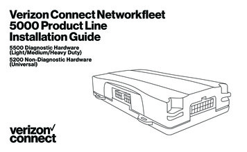
Verizon Connect Networkfleet5000 Product LineInstallation Guide5500 Diagnostic Hardware(Light/Medium/Heavy Duty)5200 Non-Diagnostic Hardware(Universal)
Table of ContentsGetting StartedRegistration form. 35000 Product LineUnit Overview. 4Harness Options for the 5000 Product Line.5-6Installation InstructionsLight/Medium Duty OBD-II Harness Installation.7-9Heavy Duty Harness Installation.10Universal Harness Installation.11-12Verifying Successful Installation. 13Creating Tamper Evidence. 14Completing Installation. 15Securing the Device. 16Optional AccessoriesOptional Window-Mount GPS Antenna Installation Instructions.17Optional Sensor Installation Instructions. 18-20Optional Garmin Installation Instructions. 21Optional NMEA Feed Installation Instructions. 22Verifying Successful Installation/LED Behavior.23-24AppendixTroubleshooting Light Indicators.25-26Frequently Asked Questions.27Contacting Networkfleet. Back Cover
Registration FormFill out the enclosed registration form beforecompleting installation.Record the following information: Vehicle Identification Number (VIN) License Plate Year Make Model Unit’s Serial number (10 digits)VehicleRegistration FormREGISTRATION INSTRUCTIONSFor self installations, please complete this form, then log in to:go.verizonconnect.com/networkfleet. In the top navigation area, click onthe Admin tab. Next, click the Registration button to complete the processusing the data on this form. For Verizon Connect Networkfleet CertifiedInstallers, please fax your completed registration form to 866.616.2131.For troubleshooting tips, please see the back of this card.Questions? Contact Verizon Connect Networkfleet Customer Care at 866.227.7323Installation Tip:Metal walls and tall buildings may interfere with thereception from GPS satellites and the cellular network.Perform installation when the vehicle is in clear viewof the sky. Conduct final installation verification afterthe vehicle has been running outside for 15 minutes.3
5000 Product Line Unit OverviewLED Indicator LightsSide of UnitNote:All 5500 and 5200 units areshipped with a knock-outpanel covering the sensor/serial ports. In order to accessthose ports, you must usean X-ACTO knife to slice off2 of the 3 tabs in order toremove the knock-out panel.Serial PortSensor PortData Port4
Harness Options for the5000 Product LineLight/Medium Duty OBD-II HarnessPrior to installation, you must select andorder the appropriate harness for our vehicletype. The Light/Medium Duty OBD-II Harnessand the Heavy Duty Harnesses are compatiblewith both the 5500 and 5200 hardwaredevices. Please refer to the list below toverify harness compatibility for eachof the 5000 series devices:Universal Harness (5200 Only)OBD-II Replacement ConnectorOBD-II Replacement tor5500 (Diagnostic Capable Hardware) Light/Medium Duty OBD-II Harness Heavy Duty Harnesses(6-pin, 9-pin, or 9-pin “D”)5200 (Non-Diagnostic Hardware) Universal Harness Light/Medium Duty OBD-II Harness Heavy Duty Harnesses(6-pin, 9-pin, or 9-pin “D”)Core Connector forthe Light/Medium DutyOBD-II Harness (X1)Harness Adapters forthe Light/Medium DutyOBD-II Harness (X8)5
Harness Options for the5000 Product LineThere are 3 different harness optionsfor Heavy Duty vehicle installations: 6-pin Harness 9-pin Harness 9-pin “D” Harness.6-pin Harness6-pin Harness9-pin Harne9-pin “D” Harness9-pin Harness9-pin “D” Harness6
Light/Medium Duty OBD-IIHarness Installation(1)(5)Select an adapter that most resembles the shape of theOBD-II port of the vehicle.Use these guidelines to match an adapter to the vehicle it ismost likely to fit (each adapter is stamped with a number).(2)(6)(3)(7)(4)(8)Ford, GM (1), (6), or (8)Honda, Lexus, Toyota, Chrysler (2)Toyota*, Chrysler* (2a)GM, Saturn (3)Mercedes, BMW (4)Porsche, Audi, Volkswagen (5)Volvo (6)Saab (7)* For certain Toyota and Chrysler vehicles, you mayneed to adjust the #2 adapter by removing the clipson the top and bottom of the adapter. To the right isan example of the adjusted adapter labeled (2a).(2a)7
Light/Medium Duty OBD-IIHarness InstallationOBD-II ReplacementConnectorCore Connector Assembly1. Snap the selected plasticadapter to the back ofthe Core Connector.2. A ttach the Core Connector to theOBD-II Replacement Connector.AdapterData Port Connection1. Connect the HarnessConnector to the Data Port.BypassConnectorCoreConnectorNetworkfleet UnitData PortHarnessConnector8
Light/Medium Duty OBD-IIHarness InstallationConnecting to the OBD-II Port1. With the vehicle’s engine OFF, remove the vehicle’s OBD-II port. The OBD-II Connector may be hidden behind a hush panel. To remove the connector, you may need toremove screws or depress the clips.2. Connect the Bypass Connector to the vehicle’sOBD-II port that was previously removed.to vehicle3. Attach the Core Connector to the position wherethe original OBD-II connector was installed.Secure it with the screws or clips removed from theOBD-II Connector’s original position (if applicable).Original OBD-II PortBypass ConnectorNetworkfleet UnitCore ConnectorDashboard9
Light/Medium Duty OBD-IIHarness InstallationConnecting to the Diagnostic Link Connector (DLC) Port1. With the vehicle’s engine OFF, unscrew the DLC portfrom its position under the dashboard*. In most cases, theDLC port is located under the dashboard on the left sideof the steering wheel, facing toward the floorboard.2. Plug the Bypass Connector of the harness into the DLC port thatwas previously removed from the vehicle in step 1. For the 9-pinconnector, turn the rotating cap clockwise to lock into place.3. Mount the Core Connector of the harness into the place in whichthe DLC port originally resided.Original DLC PortBypass Connector* Note: DLC Port Connector may also be locatednear or behind the driver seat.Networkfleet UnitCore ConnectorDashboard10
Universal Harness InstallationConnecting to Ground and PowerBlack Wire – Ground With the vehicle’s engine OFF, attach the Black Wiredirectly to a chassis ground point or to a groundline (chassis ground) by splicing directly to a groundlead or by using a wire tap (recommended).Note: Please ensure that the Driver Door isOPEN during the ENTIRE installation process.Red Wire – Continuous Power With the vehicle’s engine OFF, use the voltmeterto locate a 12-volt BATTERY lead and attachthe Red Wire by splicing directly to the lead orby using a wire tap (recommended). If attachingto a fused lead or using an in line fuse (notnecessary), verify that it is at least 5 amps. To determine a true Continuous Power source:1) Ensure the Driver Door is OPEN2) Select a wire3) W ith vehicle’s engine OFF, use a voltmeterto measure the DC voltage on the wire.It should show 12 VDC or higher. Be careful not to confuse a “Retained AccessoryPower (RAP)” line with a true ContinuousPower line (12 volt, always ON line).11
Universal Harness InstallationBlue Wire – Switched Power With the vehicle’s engine OFF, use the voltmeter tolocate an IGNITION line with switched power andattach the Blue Wire to the line by splicing directlyto the lead or by using a wire tap (recommended) Do NOT use an in line fuse on this line. Do NOT use accessory Power. To determine a switched power source:1) Ensure the Driver Door is OPEN2) Select a wire3) W ith engine OFF, use voltmeter to measure theDC voltage on the wire. It should show 0 VDC.4) Start the engine and confirm that the voltageof the same wire is 13.1 VDC or higher5) Turn the vehicle’s engine OFF and confirmthat the voltage of the same wire is 0 VDCConstant Power (Battery)Red WireNetworkfleet UnitSwitched PowerBlack WireBlue WireGround12
Verifying Successful Installation1. Start the vehicle’s engine. All lights (Red, Yellow, andGreen) on the device should turn on solid for 15 secondsand then begin blinking rapidly (twice a second).3. The vehicle must be idled or driven for atleast 15 minutes to reach normal operatingmode and ensure activation is complete.2. The device is operating normally when the rapidblinking ceases and the Green and Yellow lights beginto blink in a slow pattern (ON for 5 seconds and OFFfor 1 second). The Red light pattern will continue tovary and should not be used to verify installation.LED Light IndicatorsSide of Unit13
Creating Tamper EvidenceOnce the vehicle harness is plugged in, slide theVerizon Connect Networkfleet branded yellow zip tiesthrough the two slots provided on the harness connector.Once the zip ties are in place, tighten and removethe excess plastic. If possible, position the zip ties sothat the “DO NOT REMOVE” message is showing.14
Creating Tamper EvidenceBefore securing the device under the dashboard, makesure that you have recorded the VIN, hardware serialnumber, and odometer reading on the registration form.Also verify that you have checked the light indicators.After installation, provide the registration form to thefleet manager for delivery to Networkfleet or if you are aVerizon Connect Networkfleet Certified Installer, pleasefax to 866.616.2131 or email to installs@networkfleet.com.15
Creating Tamper EvidenceUse zip ties to fasten the hardware securely to astable bracket or wire bundle under the dash.IMPORTANT: The device must be installed highin the dashboard area and secured with the top ofthe unit facing the sky (the side of the unit with theNetworkfleet logo). Also verify that the device is notcovered by metal and check that the green LED isblinking in a slow pattern, which verifies that the unitis getting GPS data (as explained on page 13).To avoid damage from condensation, ensure thatthe unit is not at the lowest point of the installationand secure it away from moving parts.16
Optional Window-Mount GPSAntenna Installation InstructionsTo Install1. Units are shipped with a knock-out panel covering thesensor/serial ports. First, use an X-ACTO knife to slice off2 of the 3 tabs in order to remove the knock-out panel.2. Use enclosed alcohol preparation pad to clean the insidewindshield where the antenna is to be placed. For properoperation, the antenna should be placed on flat, clear glasson the driver’s side interior lower corner of the windshield.Ensure that the antenna does not extend more than 4 ½inches from the bottom of the interior windshield and islocated outside the area swept by the windshield wipers.Do NOT place the antenna in the following areas.Behind stickers or decals already on the glass, onthe shade band of the glass, on a curved area ofthe glass, on a moist or damp area of the glass, oron an area that will obstruct the driver’s view.3. Connect the window-mount GPS antenna tothe serial port on the side of the unit.4. Run the cables up the door seam orup through the dashboard.5. Remove the protective strip from theantenna to expose the adhesive.6. Carefully affix the antenna to the glass that wasprepped in Step 2. Press the antenna firmly to theglass while being careful not to damage the antenna.Note: The optional window-mount GPS antenna, the modified GarminFMI cable, or the NMEA cable cannot be used simultaneously.You may only use one of these accessories at a time.Installation Tip: Please note that the ideal temperaturerange to perform the installation is between 70 F to 100 F(21 C to 38 C) with a minimum suggested applicationtemperature of 60 F (15 C).IRE installation process.WindshieldWindow-MountGPS Antenna4 ½ inchesmax
Optional Sensor Installation InstructionsThe 5500 and 5200 devices include a sensor port formonitoring various voltage events occurring within thevehicle such as: PTO engagement/disengagement,secondary engine on/off, and door open/close.Please review prior to performing sensor installation: Installer shall use only a digital multi-meterto verify that line Voltage and Amperageare within the product tolerances. Installer shall use 24 gauge (minimum)wires for installation. Electrical connectors must be usedwhen attaching sensor wires. Voltage testing should always beperformed with a vehicle door open to avoidretained accessory power issues.The 5500/5200 comes equipped with two sensorinputs. Each sensor will be associated with a pair ofinput wires. One pair of wires (Purple, Black) will beassociated with Sensor 1 and the other pair of wires(Blue, Black) will be associated with Sensor 2.Use the Black wire of each pair to make a secure vehicleground connection. Then, connect the other wire (Blue orPurple) of each pair to the desired signal to be monitored.18
Optional Sensor InstallationInstructions (cont.)If only one wire pair (sensor input) is to be used, theother pair must be twisted together and insulated viaheat shrink or some other secure means to preventcontact with any vehicle structures and to ensure itdoes not interfere with any moving parts in the vehicle.The signal to be monitored should have two voltagestates: One where there is no voltage (i.e. zero volts whenreferenced to ground) and another that falls in the range 5 to 24 or -5 to -24 volts. The signal being monitoredshould be capable of supplying 3 mA when a voltage ispresent. It is important that the voltage signal be testedto ensure it is continuously providing the necessaryvoltage and current when in the “on” or “active” position.The following table shows how the signals are interpreted.Wire A (Black)Ground or reference for wire BWire B (Blue or Purple)Off (-3V x 3V)On (-24V x -5V or 5V x 24V)Undefined (-5V x -3V or 3V x 5V)Note: If you’re replacing a previously installed 3500/SSEM with sensor input(s) with a 5000 seriesunit, you must reinstall the sensor inputs usingthe Sensor Input Harness available for the5000 series unit. The SSEM sensor harness isNOT compatible with the 5000 series units.19
Optional Sensor Installation InstructionsTo Install1. Units are shipped with a knock-out panelcovering the sensor/serial ports. First, usean X-ACTO knife to slice off 2 of the 3 tabsin order to remove the knock-out panel.2. Connect the Sensor Input Harness to theSensor Port on the 5500 or 5200 device.3. Verify installation by checking the LED behaviorof the device (see page 23) and call CustomerCare at 866.227.7323 and select Option 5.4. Before securing the device under the dashboard,make sure you have recorded the appropriateinformation on the Sensor Installation Card includedwith the Sensor Input Harness. Once all informationis recorded, follow the instructions detailed on thecard to update your fleet on www.networkfleet.com.Serial PortSensor PortData PortSensor InputHarness(Blue & Purple)Note: The optional window-mount GPS antenna,the modified Garmin FMI cable, or the NMEAcable cannot be used simultaneously. You mayonly use one of these accessories at a time.20
Optional Garmin Installation InstructionsTo Install1. Units are shipped with a knock-out panelcovering the sensor/serial ports. First, usean X-ACTO knife to slice off 2 of the 3 tabsin order to remove the knock-out panel.2. Connect the modified Garmin FMI Cable to theSerial Port on the 5500 or 5200 device.3. Plug the other end of the modified GarminFMI cable into the Garmin device.4. R equired: To verify installation and to enableGarmin functionality, call Customer Careat 866.227.7323 and select Option 5.5. Before securing the device under the dashboard, makesure you have recorded the appropriate informationon the Garmin Installation Card included with themodified Garmin FMI Cable. Once all information isrecorded, follow the instructions detailed on the cardto update your fleet on www.networkfleet.com.Verizon Connect Networkfleet is only compatiblewith Garmin devices that support FleetManagement Interface Version 2.6 and higher.The list of compatible units can be found s.jsp(look for “Supports Version 2.6 FleetManagement Interface” in the description).All Garmin devices, even if they supportFleet Management Interface Version 2.6, willneed a firmware update prior to installation.Please contact your sales representative orVerizon Connect Networkfleet CustomerCare to obtain update instructions.Note: The optional window-mount GPS antenna,the modified Garmin FMI cable, or the NMEAcable cannot be used simultaneously. You mayonly use one of these accessories at a time.21
Optional NMEA FeedInstallation InstructionsLocation data is available directly from the 5000 serieshardware to another in cab device via our serial portinterface. The feed is in NMEA format and requiresa 5000 series hardware device, a Verizon ConnectNetworkfleet NMEA Cable, and a terminating devicesuch as a laptop that can accept NMEA data.3. Verify installation by checking the LED behavior ofthe device and call Customer Care at 866.227.7323and select Option 5. The device is operatingnormally when the rapid blinking ceases andthe Green LED begins to blink in a slow pattern(ON for 5 seconds and OFF for 1 second).To Install4. Before securing the device under the dashboard,make sure you have recorded the appropriateinformation on the Installation Card included withthe NMEA Cable. Once all information is recorded,follow the instructions detailed on the card.1. Units are shipped with a knock-out panelcovering the sensor/serial ports. First, usean X-ACTO knife to slice off 2 of the 3 tabsin order to remove the knock-out panel.2. Connect the NMEA Cable to the SerialPort on the 5500 or 5200 device.Note: The optional window-mount GPS antenna,the modified Garmin FMI cable, or the NMEAcable cannot be used simultaneously. You mayonly use one of these accessories at a time.22
Verifying SuccessfulInstallation/LED BehaviorTo verify successful installation, call CustomerCare at 866.227.7323 and select Option 5.LED Behavior for Sensors:When the Sensor Input Harness is detected by theunit, all LEDs should be turned on solid for 10 seconds.When you engage Sensor 1 (if installed), the yellow LEDshall blink rapidly (1/4 second) every time a transition isdetected (on to off/off to on). When you engage Sensor 2(if installed), the green LED shall blink rapidly (1/4 second)every time a transition is detected (on to off/off to on).The sensor installation verification will take one minutein total. Afterwards, all LEDs should be turned on for 10seconds and then normal LED behavior will resume.To ensure activation is complete, the vehiclemust be idled or driven for at least 15 minutesto reach normal operating mode.Note: If voltage does not meet the standards detailedin this guide, the installation may require the useof a relay switch to properly connect the sensor.23
Verifying SuccessfulInstallation/LED BehaviorLED Behavior for Garmin:When the Garmin or window-mount GPS antennais connected to the serial port, all LEDs should beturned on solid for 10 seconds. Afterwards, thered LED shall double blink every two seconds. Theinstallation verification will take one minute in total,then all LEDs should be turned on for 10 seconds.Thereafter, then normal LED behavior will resume.Please note that the blinking pattern shows successfulconnection with the device, but it does not verifysuccessful communication with the Verizon ConnectNetworkfleet website. To verify successful installation,call Customer Care at 866.227.7323 and select Option 5.24
Appendix: TroubleshootingLight IndicatorsIssue:Red light continues to blink rapidlySolution: Verify that the unit is notsurrounded by metal. Contact Customer Care to confirm networkcoverage availability and the SIM is active.Issue:Yellow light continues to blink rapidlySolution: Contact Customer Care to verifyengine computer compatibility. If incompatible, install aUniversal device (5200).Issue:Green light continues to blink rapidlySolution: With the vehicle’s engine OFF, unplug thedevice for 3 minutes and check each itembelow before reconnecting. Verify that the unit is notsurrounded by metal.If using the window-mount GPS antenna: Disconnect the GPS Antenna wire andcheck the antenna wire and connectorfor damage. Reconnect the GPS antennawire to the serial port. Reconnect device, start engineand keep the vehicle runningor drive it for 10-15 minutes.25
Appendix: TroubleshootingLight IndicatorsIssue:Yellow light stays on solidSolution: Verify that you are in an area withwireless coverage. Wait 15 minutes with the vehicle’s engine on. Verify web portal activation has beencompleted.Issue:Green light stays on solidSolution: Verify that the unit was installed properly.The side of the unit with the Networkfleetlogo should be facing the sky. Make certain that the unit is not blocked byunderground parking structures, metal, ortrees. If using the window-mountGPS antenna: Disconnect the GPS Antenna wire andcheck the antenna wire and connectorfor damage. Reconnect the GPS antenna wire to theserial port. Reconnect device, start engine andkeep the vehicle running or drive it for10-15 minutes.26
Frequently Asked QuestionsQ: Are the 5000 series harnesses interchangeable between allother Verizon Connect Networkfleet product lines?Q: I need to do a unit transfer. Can I re-use the window-mountGPS antenna? How do I remove it from the glass?A: No.A: Yes, however the adhesive on the antenna is one-timeuse only and will not function properly after it is removed.Re-installation kits are available - contact Customer Care at866.227.7323 for more information.Q: When installing the 5200 device, are fuses involved or canthe device be “wired hot”?A: We recommend splicing the 5200 harness to fused leads,though the device can be “wired hot” since there is aninternal re-settable fuse. An in line fuse is not necessary,however if one is used, it should be at least 5 amps.Q: Can the window-mount GPS antenna be installed in theA-Pillar?A: No, the antenna is designed so that it will only functionproperly with a clear view of the sky which is best achievedby placing it on the glass windshield.Instructions for Window-Mount GPS Antenna RemovalBecause of the strength of the antenna adhesive, use a razor orGoo Gone (a household solvent) for removal.1. To remove the antenna with a razor, peel a small section of theantenna off of the glass and slide the razor between the glassand the antenna.2. Using a sawing motion, carefully remove the antenna from theglass and discard.27
If you have any additional questions, you may contactVerizon Connect Networkfleet Customer Care:Toll Free Number: 866.227.7323Email: /networkfleetFor questions or more information, contact your Customer Success Manager oremail sdcustomersuccess@verizonconnect.com 2018 Verizon. All rights reserved.
Secure it with the screws or clips removed from the OBD-II Connector's original position (if applicable). . DC voltage on the wire. It should show 0 VDC. 4) Start the engine and confirm that the voltage . fax to 866.616.2131 or email to installs@networkfleet.com. 16 Creating Tamper Evidence

