Transcription
AIR CONDITIONERSEL16XC1ELITE SeriesR-410A - 60 HzBulletin No. 210833July 2020RESIDENTIALP R O D U C T S P E C I F I C AT I O N SSupersedes May 2020SEER up to 17.851.5 to 5 TonsCooling Capacity - 17,800 to 60,000 BtuhM ODEL NU MBER IDENTIF IC ATIONEL 16 X C 1 - 036 - 230 A 01Product TierEL Elite SeriesRevision LevelNominal SEER16 16 SEERRefrigerant TypeX R-410AUnit TypeC Air Conditioner (Condenser)Cooling Stages1 Single Stage CompressorRegional Standards– (dash) All RegionsS Southeast and North RegionsRatings Revision LevelVoltage230 208/230V-1 phase-60hzNominal Cooling Capacity018 1.5 tons024 2 tons030 2.5 tons036 3 tons041 3.5 tons042 3.5 tons047 4 tons048 4 tons060 5 tons
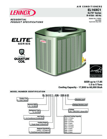
F EAT URE HIG HLIGHTSGB1.2.3.4.5.Outdoor Coil FanQuantum CoilHigh Capacity Liquid Line DrierHigh Pressure SwitchScroll CompressorHCCF6. Heavy Gauge Steel Cabinet7. SmartHinge Louvered Coil Protection8. Refrigerant Line Connections and AccessEDICON T ENTSApprovals And Warranty . . . . . . . . . . . . . . . . . . . . . . . . . . . . . . . . . . . . . . . . . . . . . . . . . . 3Controls - Order Separately . . . . . . . . . . . . . . . . . . . . . . . . . . . . . . . . . . . . . . . . . . . . . . . . 8Dimensions - Unit . . . . . . . . . . . . . . . . . . . . . . . . . . . . . . . . . . . . . . . . . . . . . . . . . . . . . 10Electrical Data . . . . . . . . . . . . . . . . . . . . . . . . . . . . . . . . . . . . . . . . . . . . . . . . . . . . . . . 7Features . . . . . . . . . . . . . . . . . . . . . . . . . . . . . . . . . . . . . . . . . . . . . . . . . . . . . . . . . . . 3Field Wiring . . . . . . . . . . . . . . . . . . . . . . . . . . . . . . . . . . . . . . . . . . . . . . . . . . . . . . . . . 9Installation Clearances . . . . . . . . . . . . . . . . . . . . . . . . . . . . . . . . . . . . . . . . . . . . . . . . . . 9Optional Accessories - Order Separately . . . . . . . . . . . . . . . . . . . . . . . . . . . . . . . . . . . . . . . . . 7Sound Data . . . . . . . . . . . . . . . . . . . . . . . . . . . . . . . . . . . . . . . . . . . . . . . . . . . . . . . . . 9Specifications . . . . . . . . . . . . . . . . . . . . . . . . . . . . . . . . . . . . . . . . . . . . . . . . . . . . . . . . 7TXV/Orifice Usage . . . . . . . . . . . . . . . . . . . . . . . . . . . . . . . . . . . . . . . . . . . . . . . . . . . . 11EL16XC1 - 1.5 to 5 Ton Air Conditioner / Page 2
AP PROVALS A ND WARRANT YAPPROVALS AHRI Standard 210/240 certified AHRI Certified system match-ups and expanded ratings, visit www.LennoxPros.com ENERGY STAR Certified (certain units) Sound rated to AHRI Standard 270-2008 test conditions Tested in Lennox’ Research Laboratory environmental test room Rated According to U.S. Department of Energy (DOE) test procedures Region specific models meet the minimum efficiency requirements for U.S. DOE Federal Regional Standards in that area Unit and components ETL, NEC and CEC bonded for grounding to meet safety standards for servicing ETL certified (U.S. and Canada) ISO 9001 Registered Manufacturing Quality SystemWARRANTY Compressor: Limited ten years in residential installations Limited five years in non-residential installations All other covered components: Limited five years in residential installations Limited one year in non-residential installationsNOTE - Refer to Lennox Equipment Limited Warranty certificate included with unit for specific details.F EAT URESAPPLICATIONS 1.5 through 5 ton Sound levels as low as 71 dBA Single-phase power supply Vertical air discharge Applicable to indoor air handlers or gas furnaces withindoor add-on coils Shipped completely factory assembled, piped and wired Factory test operatedREFRIGERATION SYSTEMR-410A Refrigerant Non-chlorine, ozone friendly Unit is factory pre-chargedB Outdoor Coil Fan Direct drive fanVertical air dischargeTotally enclosed fan motorSleeve bearingsInherently protectedPVC (polyvinyl chloride) coated steel fan guardC Quantum Coil Lennox designed and fabricated coilEnhanced aluminum alloy tube/enhanced fin coilSuperior corrosion resistanceRipple-edged aluminum finsAluminum tube constructionLanced fins for maximum fin surface exposureFin collars grip tubing for maximum contact areaFlared shoulder tubing connectionsFactory tested under high pressureEntire coil is accessible for cleaningD High Capacity Liquid Line Drier Factory installed in the liquid line Drier traps moisture or dirt 100% molecular-sieve, bead type, bi-flow drierE High Pressure Switch Protects the system from high pressure conditions Automatic resetDischarge Thermostat Factory installed on the discharge line of the compressor SPST Automatic reset Removes power to the compressor when dischargetemperature exceeds the factory setting of 220ºFEL16XC1 - 1.5 to 5 Ton Air Conditioner / Page 3
F EAT URESREFRIGERATION SYSTEM (continued)COMPRESSORRefrigerant Flow Control Units applicable toRFCIV METERING SYSTEMRFCIVexpansion valveORIFICE BODY(On Coil)systems or RFCORIFICEsystems whenmatched withLIQUIDspecific indoor coils O RINGLINERFCIV:LIQUID Accurately metersLINE SCREENrefrigerant inSEALsystemNUTSWEATCONNECTION Refrigerant controlis accomplished by exact sizing of refrigerant meteringorifice The principle involves matching indoor coil with properbore size of orifice in metering device Equalizes pressure shortly after compressor stops, unitstarts unloaded Eliminates need for additional controls Furnished with air conditionerOptional AccessoriesExpansion Valve Kits Field installed on certain indoor units See TXV/Orifice Usage table Chatleff-style fittingFreezestat Senses suction line temperature Cycles compressor off when suction line temperaturefalls below it’s setpoint Opens at 29 F and closes at 58 F Installs on or near the discharge line of the evaporator oron the suction lineLoss of Charge Switch Kit Protects compressor from damage from low refrigerantcharge conditions SPST, normally-closed Automatic resetRefrigerant Line Kits Refrigerant lines are shipped refrigeration clean Lines are cleaned, dried, pressurized and sealed atfactory Suction line fully insulated Lines are stubbed at both endsNOTE - Not available for -060 models. Must be fieldfabricated.EL16XC1 - 1.5 to 5 Ton Air Conditioner / Page 4F Scroll Compressor High efficiency with uniformsuction flow Constant discharge flow, highvolumetric efficiency and quietoperation Low gas pulses duringcompression reduces operationalsound levels Compressor motor is internallyprotected from excessive currentand temperature Muffler in discharge line reducesoperating sound levels Compressor is installed inthe unit on resilient rubber mounts for vibration freeoperationScroll Compressor Operation Two involute spiral scrolls matched together generate aseries of crescent-shaped gas pockets between them During compression, one scroll remains stationary whilethe other scroll orbits around it Gas is drawn into the outer pocket, the pocket is sealedas the scroll rotates As the spiral movement continues, gas pockets arepushed to the center of the scrolls. Volume between thepockets is simultaneously reduced When the pocket reaches the center, gas is now at highpressure and is forced out of a port located in the centerof the fixed scrolls During compression, several pockets are compressedsimultaneously resulting in a smooth continuouscompression cycle Continuous flank contact, maintained by centrifugalforce, minimizes gas leakage and maximizes efficiency Compressor is tolerant to the effects of slugging andcontaminants. If this occurs, scrolls separate, allowingliquid or contaminants to be worked toward the centerand dischargedCompressor Crankcase Heater (060 Models) Protects against refrigerant migration that can occurduring low ambient operation Factory InstalledCompressor Sound Dampening System Polyethylene compressor 2 inch thick batt fiberglass insulation All open edges sealed with one-inch wide hook and loopfastening tape
F EAT URESCOMPRESSOR (continued)Optional AccessoriesCompressor Crankcase Heater (018 thru 048 models) Protects against refrigerant migration that can occurduring low ambient operationCompressor Hard Start Kit Single-phase units are equipped with a PSC compressormotor This type of motor normally doesn’t need a potentialrelay and start capacitor For conditions such as low voltage kit may be requiredto increase the compressor starting torqueCompressor Low Ambient Cut-Off Switch Non-adjustable switch (low ambient cut-out) preventscompressor operation when outdoor temperature isbelow 35 FCONTROLSOptional AccessoriesiComfort E30 Smart Wi-Fi Thermostat Wi-Fi enabled, electronic 7-day, universal, multi-stage,programmable, touchscreen thermostat 3 Heat/2 Cool Auto-changeover Controls dehumidificationduring cooling mode andhumidification duringheating mode Offers enhancedcapabilities includinghumidification / dehumidification / dewpointmeasurement and control, Humiditrol control, andequipment maintenance reminders Easy to read 7 in. color touchscreen (measured diagonally) LCD display with backlight shows the current and settemperature, time, inside relative humidity, systemstatus (operating mode and schedules) and outsidetemperature (optional outdoor sensor required) Smooth Setback Recovery starts system early toachieve setpoint at start of program period Compressor short-cycle protection (5 minutes) Up to four separate schedules are available plusSchedule IQ One-Touch Away Mode - A quick and easy way to set thecooling and heating setpoints while away Smart Away - Uses geo-fencing technologyto determine when the homeowner is within apredetermined distance from the home to operate thesystem when leaving, away and arriving Wi-Fi remote monitoring and adjustment through ahome wireless network for desktop PCs, laptops andapps for smartphones or tablets Smart home automation compatible with AppleHomeKit , Amazon Alexa , Google Assistant and IFTTT Service Dashboard features online real-time monitoringof installed iComfort thermostats High Definition Color Display with Subbase, Smart HubController, wallplate (for retrofit installations) furnishedfor easy installation See the iComfort E30 Smart Wi-Fi Thermostat ProductSpecifications bulletin for more informationRemote Outdoor Temperature Sensor Used with the iComfort E30 Smart Wi-FIiThermostat When installed outdoors, sensorallows thermostat to display outdoortemperature Sensor is auto-detected whenconnected to thermostatNOTE - Sensor is required for theEnhanced DehumidificationAccessory (EDA).Thermostat Thermostat is not furnished with unit See Lennox Price Book for selectionIndoor Blower Off Delay Relay Delays the indoor blower-off time during the coolingcycleLow Ambient Kit Air conditioners can operate down to 45 F outdoor airtemperature without additional controls Allows unit to operate properly down to 30 FNOTE - Crankcase heater and freezestat should beinstalled on compressors equipped with a lowambient kit.NOTE - A compressor lock-out thermostat should beadded to terminate compressor operation belowrecommended operation conditions.Compressor Timed-Off Control Prevents compressor short-cycling Allows time for suction and discharge pressure toequalize Permits compressor start-up in an unloaded condition Automatic reset with 5 minute delay betweencompressor shut-off and start-upEL16XC1 - 1.5 to 5 Ton Air Conditioner / Page 5
F EAT URESCABINETG Heavy-gauge steel construction Pre-painted cabinet finish Louvered heavy gauge steel panels surround unit on allfour sides Control box is conveniently located with all controlsfactory wired Corner patch plate allows access to compressorcomponents Drainage holes are provided in base section for moistureremoval High density polyethylene unit support feet raise theunit off of the mounting surface, away from damagingmoisturePermaGuard Unit Base Durable zinc-coated base section resists rust andcorrosionH SmartHinge Louvered Coil Protection Steel louvered panels providescomplete coil protection Panels are hinged to allow easycleaning and servicing of coils Panels may be completelyremoved Interlocking tabs and slotsassure tight fit on cabinetI Refrigerant Line Connections,Electrical Inlets and Service Valves Sweat connection suction and liquid lines Located on corner of unit cabinet Suction valve can be fully shut off, while liquid valvemay be front seated to manage refrigerant charge whileservicing system Refrigerant line connections and field wiring inlets arelocated in one central area of the cabinet See dimension drawingEL16XC1 - 1.5 to 5 Ton Air Conditioner / Page 6
SP ECIFICATION SGeneralDataModel No.Southeast and North All Regions -EL16XC1S036Nominal Tonnage1.522.53Liquid line (o.d.) - in.3/83/83/83/8Suction line (o.d.) - in.3/43/43/47/84 lbs. 9 oz.4 lbs. 9 oz.5 lbs. 8 oz.7 lbs. 1 oz.13.2216.3321.0016.33R-410A charge furnishedNet face area - sq. ft.Outer coilInner coil---------15.75Tube diameter - in.5/165/165/165/16No. of rows1112OutdoorFanFins per inch26262622Diameter - in.18222222No. of blades3333Motor ated load amps9.010.912.813.6Locked rotor amps4859.367.879Power factor0.970.970.970.96Full load amps0.7111Locked rotor amps1.31.91.91.9Shipping Data - lbs. 1 pkg.ELECT RICAL DATALine voltage data - 60hz2Maximum overcurrent protection (amps)3Minimum circuit ampacityCompressorOutdoor Fan MotorCONT ROLSiComfort E30 Smart Wi-Fi Thermostat15S63 Remote Outdoor Temperature SensorX2658 OPT IONAL AC C ES S ORIES - ORDER S EPARATELYCompressor Crankcase HeaterCompressor HardStart Kit93M04 Copeland10J42 LG88M91 45F08 Compressor Low Ambient Cut-Off SwitchCompressor Timed-Off Control47J35 3/8 in. tubing93G35 5/8 in. tubing50A93 Indoor Blower Off Delay Relay58M81 Loss of Charge Switch Kit84M23 Freezestat4Low Ambient Kit (Fan Cycling)RefrigerantLine Sets34M72 L15-41-20L15-41-30L15-41-40L15-41-50 L15-65-30L15-65-40L15-65-50 NOTE - Extremes of operating range are plus 10% and minus 5% of line voltage.1 Refrigerant charge sufficient for 15 ft. length of refrigerant lines. For longer line set requirements see the Installation Instructions for information about line set length andadditional refrigerant charge required.2HACR type breaker or fuse.3Refer to National or Canadian Electrical Code manual to determine wire, fuse and disconnect size requirements.4Crankcase Heater and Freezestat are recommended with Low Ambient Kit.EL16XC1 - 1.5 to 5 Ton Air Conditioner / Page 7
S P ECIFICAT IONSGeneralDataModel No.All Regions EL16XC1-041 EL16XC1-042 EL16XC1-047 EL16XC1-048 3/8Suction line (o.d.) - in.RefrigerantOutdoorCoilNominal TonnageLiquid line (o.d.) - in.17/87/87/87/81-1/89 lbs. 9 oz.8 lbs. 12 oz.11 lbs. 0 oz.9 lbs. 12 oz.12 lbs. 0 oz.Outer coil21.0021.0022.1721.0029.09Inner coil20.2520.2521.3320.2528.16Tube diameter - in.5/165/165/165/165/16R-410A charge furnishedNet face area - sq. ft.OutdoorFanNo. of rows22222Fins per inch2222222222Diameter - in.2222262226No. of blades33443Motor 5825825Watts190190310310310227234272255284Shipping Data - lbs. 1 pkg.ELECT RICAL DATALine voltage data - 60hz208/230V-1ph 208/230V-1ph 208/230V-1ph 208/230V-1ph 208/230V-1ph2Maximum overcurrent protection (amps)3Minimum circuit ampacityCompressorRated load ampsLocked rotor ampsPower factorOutdoor Fan MotorFull load ampsLocked rotor 1.81.91.92.93.22.9C ON T ROLS - ORDER S EPA RATELYiComfort E30 Smart Wi-Fi Thermostat15S63 Remote Outdoor Temperature SensorX2658 OP T IONAL ACCES S ORIES - ORDER S EPARATELYCompressor Crankcase Heater93M04 93M06FactoryCompressor HardStart Kit Copeland10J42LG88M91 Compressor Low Ambient Cut-Off Switch45F08 Compressor Timed-Off Control47J35 Freezestat3/8 in. tubing93G35 5/8 in. tubing50A93 Indoor Blower Off Delay Relay58M81 Loss of Charge Switch Kit84M23 34M72 L15-65-40 4Low Ambient Kit (Fan Cycling)RefrigerantLine SetsL15-65-30 L15-65-50Field Fabricate NOTE - Extremes of operating range are plus 10% and minus 5% of line voltage.1 Refrigerant charge sufficient for 15 ft. length of refrigerant lines. For longer line set requirements see the Installation Instructions for information about line set length andadditional refrigerant charge required.2HACR type breaker or fuse.3Refer to National or Canadian Electrical Code manual to determine wire, fuse and disconnect size requirements.4Crankcase Heater and Freezestat are recommended with Low Ambient Kit.EL16XC1 - 1.5 to 5 Ton Air Conditioner / Page 8
SOU ND DATAOctave Band Sound Power Levels dBA, re 10-12 WattsCenter Frequency - 51.549.55453.5UnitModel11² Estimated Sound Pressure Level atDistance From Unit (dBA at distance in 54524039414040404341NOTE - The octave sound power data does not include tonal correction.1Tested according to AHRI Standard 270-2008 test conditions.2 Estimated sound pressure level at distance based on AHRI Standard 275-2010 method for equipment located on the ground, roof, or on side of building wall with noadjacent reflective surface within 9.8 feet. Sound pressure levels will increase based on changes to assumptions. For other applications, refer to AHRI Standard 275.F IELD WIRINGDISCONNECTSWITCH(By Others)DISCONNECTSWITCH(By CLENNOXHEATING UNITORAIR HANDLERUNITA - Two Wire Power (not furnished)B - Two Power (not furnished). See Electrical DataC - Four Wire Low Voltage (not furnished). 18 ga. minimumD - Five Wire Low Voltage (not furnished). 18 ga. minimumAll wiring must conform to NEC or CEC and local electrical codes.INSTALL AT ION C LEA RANC ESNOTES:See NOTESService clearance of 30 in. (762 mm) must be maintained on oneof the sides adjacent to the control box.Clearance to one of the other three sides must be 36 in. (914 mm)SeeNOTESSeeNOTESSee NOTESControlBoxClearance to one of the remaining two sides may be 12 in. (305mm) and the final side may be 6 in. (152 mm).A clearance of 24 in. (610 mm) must be maintained between twounits.48 in. (1219 mm) clearance required on top of unit.EL16XC1 - 1.5 to 5 Ton Air Conditioner / Page 9
D IM ENSIONS - UN ITSUCTION LINECONNECTIONLIQUID LINECONNECTIONTOP VIEWC (depth)B (width)DISCHARGE AIRLIQUID LINECONNECTIONELECTRICALINLETSASUCTION LINECONNECTION2 (51)4 3/44 1/4(108) (121)1 (25)SIDE VIEWUNIT SUPPORTFEETUNIT SUPPORTFEET8 1/2(216)8 3/4(222)5 1/2(140)9 1/2(241)D8 036 C1-048EL16XC1-060in.28353531 787 30-1/2 775353539353945J889 30-1/2991 30-1/2889 35-1/2991 30-1/21143 35-1/2GFABmm in. mm787 27 686787 30-1/2 775991 30-1/2 775in.313139K13 1/2(343)EL16XC1-018 BASE SECTION(Small Base)Model No.END VIEWCEL16XC1 - 1.5 to 5 Ton Air Conditioner / Page 10EL16XC1-024 TO -060 BASE SECTION(Medium and Large Base)DEmm in. mm in.711 - - - - - - - - 889 13-7/8 352 7-3/4889 13-7/8 352 7-3/4Fmm in.--- --197 3-1/4197 3-1/4Gmm in.--- --83 27-1/883 27-1/8Hmm in.--- --689 3-5/8689 3-5/8889 13-7/8 352 7-3/4 197 3-1/4 83 27-1/8 689 3-5/8775 35 889 13-7/8775 35 889 13-7/8902 39-1/2 1003 16-7/8775 35 889 13-7/8902 39-1/2 1003 1/827-1/830-3/427-1/830-3/4689689781689781JKmm in. mm in.--- --- --- --92 4-1/2 114 20-5/892 4-1/2 114 20-5/8mm--52452492 4-1/2 114 20-5/8 5243-5/8 92 4-1/2 1143-5/8 92 4-1/2 1144-5/8 117 3-3/4 953-5/8 92 4-1/2 1144-5/8 117 3-3/4 9520-5/820-5/826-7/820-5/826-7/8524524683524683
T X V/ORIFICE US AGETX V S U BS TI TU TIO NUse this table for C35, CH23, CH35 and CR33 FieldInstalled TXV/Orifice Match-UpsA general guide for replacing the factory installed TXV if theindoor unit (coil/air handler) is larger than the outdoor unit.Model No.Refrigerant MeteringOrifice (RFC)Order No.Orifice SizeThermalExpansionValve 5712J18EL16XC1-03010W990.06512J18EL16XC1-036 712J20CX35 and CHX35 coils and all Lennox air handlers are shipped with a factoryinstalled TXV. In most cases, no change out of the valve is needed.If a change out is required it will be listed in the “TXV SUBSTITUTIONS” tableby size. The correct TXV must be ordered separately and field installed.C35 and CH35 coils - Use the RFC orifice shipped with the outdoor unit orreplace the factory installed RFC orifice with the expansion valve listed.CR33 and CH23 coils - Use the RFC orifice shipped with the outdoor unit oruse the expansion valve listed.Outdoor UnitIndoor UnitTXVTXVFurnished J180302.550/60412J2012J18TXV Ranges:12J18 - 1 .5 to 2.5 ton systems - Use on 2.5 ton and lowersystems.12J19 - 3 ton systems - Use down to 2 ton systems.12J20 - 3.5 to 5 ton systems - Use down to 3 ton systems.AH RI S TA ND AR D 210/240Cooling or heating capacities are net values, includingthe effects of blower motor heat, and do not includesupplementary heatPower input is the total power input tothe compressor(s) and fan(s), plus any controls and otheritems required as part of the system for normal operation.Units which do not have an indoor air-circulating blowerfurnished as part of the model, i.e., split system withindoor coil only, is established by subtracting from thetotal cooling capacity 1250 Btu/h per 1,000 cfm, and byadding the same amount to the heating capacity. Totalpower input for both heating and cooling is increased by365 W per 1,000 cfm of indoor air circulated.EL16XC1 - 1.5 to 5 Ton Air Conditioner / Page 11
R EVISIONSSectionsDescription of ChangeDimensionsUpdated for 036 model.Electrical DataUpdated for 036 model.SpecificationsUpdated for 036 model.Visit us at www.Lennox.comFor the latest technical information, www.LennoxPros.comContact us at 1-800-4-LENNOXNOTE - Due to Lennox’ ongoing commitment to quality, Specifications, Ratings and Dimensions subject to change without notice and without incurring liability.Improper installation, adjustment, alteration, service or maintenance can cause property damage or personal injury.Installation and service must be performed by a qualified installer and servicing agency. 2020 Lennox Industries, Inc.
Coil Net face area - sq. ft. Outer coil 13.22 16.33 21.00 16.33 Inner coil - - - - - - - - - 15.75 Tube diameter - in. 5/16 5/16 5/16 5/16 No. of rows 1 1 1 2 Fins per inch 26 26 26 22 Outdoor Fan Diameter - in. 18 22 22 22 No. of blades 3 3 3 3 Motor hp 1/10 1/6 1/6 1/6 Cfm 2290 3160 3160 3160 Rpm 1075 825 825 825 Watts 160 215 215 190