Transcription
Operating Manual
2Congratulations on your purchase of theProMark Apex Locator with touch screen.Please do not hesitate to contact DENTSPLYTulsa Dental Specialties for help or if you haveany questions. Keep this manual for furtherreference.DENTSPLY Tulsa Dental Specialties reservesthe right to change the information and datacontained in these Directions For Use at anytimeand without prior notice.These Directions For Use are available in Frenchupon request.DENTSPLY Tulsa Dental SpecialtiesDENTSPLY International, Inc.608 Rolling Hills DriveJohnson City, TN 376041-800-662-12021-800-597-2779 (fax)www.DENTSPLY.comwww.DENTSPLY.com/endo-patents
3Contents1Identification of Symbols . 47.6.2DR’S CHOICE Working Length Line . 161.1Symbols used in theseDirections for Use . 47.6.3CHECK Mode . 181.2Symbols used on Packaging,Device and Parts . 47.6.4DEMO Mode .208Maintenance, Cleaning andSterilization .212Indications for Use . 58.1General .218.2Disinfection and SterilizationProcedure .223Contraindications . 54Warnings . 59Manufacturer .235General Precautions . 610Warranty .236Adverse Reactions . 611Disclaimer .237Step-by-Step Instructions . 612Technical Data . 247.1Standard Components . 67.2Installation . 7Annex7.2.1Charger . 7Electromagnetic Compatibility .257.2.2Rechargeable Battery . 77.3Description of User Interface . 87.4Operation . 97.4.1Connecting the Device . 97.4.2Starting Length Determination . 107.4.3Apex Localization . 117.4.4Sound Level Selection . 127.4.5Automatic Shutdown . 137.5Length Determination . 137.5.1Troubleshooting . 147.5.2Comparison of Electronic LengthDetermination Versus Radiography . 157.6Device Setup . 157.6.1Settings Menu Features . 16
41 Identification of Symbols1.1 Symbols used in these Directions for UseWARNINGIf the instructions are not being followed properly, operation may resultin hazards for the product or theuser/patient.NOTEAdditional information, explanationon operation and performance.1.2 Symbols used on Packaging, Device and PartsSerial numberConsult Instructions For UseClass II productSpecial disposal of waste electricaland electronic equipment(Directive 2002/96/EEC)Shock Type BFFragileKeep dry!Content (quantity)X-rayDirect currentTemperature limitationAtmospheric pressure limitationHumidity limitation
52 Indications for UseFOR DENTAL USE ONLY!ProMark is a microprocessor controlled deviceused for locating apex. Do not use the device as an integralcomponent of any other apparatus orinappropriate system. DENTSPLY TulsaDental Specialties will not be responsiblefor accidents, equipment damage, bodilyinjury or any other trouble which resultsfrom ignoring this prohibition.3 ContraindicationsUse of the ProMark is contraindicated onpatients or by operators having implantedelectronic devices such as pacemaker, etc.4 WarningsIn this chapter a description of serious adversereactions and potential safety hazards for theproduct or the user/patient is included.Please read the following warnings before use.WARNINGS The device may be used only bylicensed dentists acting in accordance withfederal, state or provincial regulations. Do not expose the device to direct orindirect sources of heat. Store and use thedevice in a safe environment. Do not use the device in the presence offlammable anaesthetic mixtures. Do not immerse in liquid. Use only original accessories andbattery. Do not use the device if it appears to bedamaged or defective. Do not perform repairs or modificationsto the device without prior authorization byDENTSPLY Tulsa Dental Specialties. Do not connect the device to or use it incombination with any other apparatus orsystem. Device only works while running onbattery power.NOTEThe device complies with theElectromagnetic compatibility standard(IEC 60601-1-2).
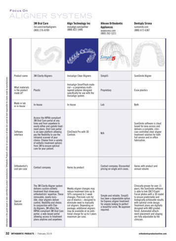
65 General PrecautionsRead these safety precautions thoroughly priorto use. These precautions allow you to use theproduct safely, preventing harm to you and toothers.It is of the utmost importance that this manual ispreserved for future reference.It is recommended to take an X-ray prior to theuse of the device and to compare the resultsobtained by both methods.The manufacturer declines any responsibility inthe case of: Use of the device for applications other thanthose specified in the directions for use. Modifications or repairs performed by personsnot authorized by the manufacturer. Use of non-original components or componentsother than those specified in the STANDARDCOMPONENTS chapter (7.1).Ambient Conditions for Operation Ambient temperature: 10 C to 40 C(50 F to 104 F). Relative humidity: 10% to 90%. Atmospheric pressure: 70 kPa to 106 kPa.WARNINGDo not store the device in damp placesor in places where it will come intoextended contact with liquids of anykind.6 Adverse ReactionsThere are no known adverse reactions.7 Step-by-Step InstructionsRefer to the WARNINGS chapter (4) to verify anyspecial care to exercise before starting to use thedevice.When opening the package and prior toinstallation, check the device for completeness.Report any damage sustained during shippingor any missing parts to DENTSPLY Tulsa DentalSpecialties within 24 hours of opening of thedevice.Fig. 1 Incorrect placement of device.7.1 Standard Components 1 ProMark Apex Locator. 1 Charger. 1 Tester for operation check. 1 Accessory set including: 1 measuringcable, 2 lip clips, 2 file clips, 1 touch probe. Directions For Use.NOTENone of the accessories is delivereddisinfected or sterilized!
77.2 Installation7.2.1 ChargerAttach the charger plug adapter (Fig. 2). Slidethe plug adapter downwards into the slots until itlocks in place with a click.USA /Canada plug adapterFig. 3 Battery symbol is flashing redFig. 2 Plug adapter and chargerWARNINGS Prior to first use, the battery must becharged for 6 hours! Use the original charger only.NOTEThe device with flashing red batterysymbol is still functional and maypossibly be used for several treatmentsbefore the device shuts down.Charging Screen only shown when connectedto chargerBattery status during battery charging is shownon the charging screen:Red: charging, low battery level7.2.2 Rechargeable BatteryProMark is powered by a Nickel-Metal Hydride(NiMH) rechargeable battery. Battery statusduring the operation is shown on the mainscreen:Battery Symbol only shown when disconnectedfrom chargerWhite: indicates battery level from fully chargedto approximately 20% of capacity.Flashing red: When battery level drops under20%, the indicator will turn red and startflashing. The battery needs to be recharged(Fig. 3).Yellow: charging, medium battery levelGreen: charging completed, batteryfully chargedTo charge the battery, follow the next steps: Make sure that the measurement cable is notconnected to the patient. Remove the measuring cable from ProMark . Connect the external charger to the device jackand plug it into the power outlet. If the battery is fully discharged, e.g. when ithas not been used for a long period of time, itmust be recharged for 6 hours. If the battery is low, 4 hours recharging issufficient.
87.3 Description of User InterfaceWARNINGSFor removing the charger, follow thesequence below: Before removing the external chargerfrom the power outlet, disconnect thecharger from the device. The device cannot be used whilecharging.Battery ReplacementThe battery compartment is located at the rear ofProMark and its cover is secured by screws. Ensure charger is disconnected from the unitbefore beginning battery replacement. Release the screws and remove the batterycompartment cover (Fig. 5). Remove the battery from battery compartmentand disconnect the battery cable plug from thebattery jack of ProMark . Insert the cable plug of the new battery into thebattery jack. Insert the battery into the batterycompartment. Close the battery compartment and secure thecover with the screws.WARNINGS Before replacing the battery, disconnect the charger from the device! The used battery must be disposed ofin accordance with local regulationsProMark has a tilt adjustable front panel with alarge graphic touch screen.The main screen shows the following icons andsymbols:Settings iconSound iconMeasuring cable connectorand lip clip/ file clip symbolsFull canal imageApical zoom imageStandby Mode Icon
9ProMark Overview7.4 OperationFront viewTouch screenOn/OffMeasuringcable/chargercable receptacle(jack)Rubbernon-slip padsFig. 4 ProMark front viewImportant Advice for successfuldetermination Always use a rubber dental dam toisolate the working area. Always wear gloves during themeasuring procedure. Prior to measuring the access cavitymust be dried with a cotton pellet inorder to prevent incorrect measurement. Select the size of the measuring fileto match the root canal diameter.7.4.1 Connecting the Device Press the On/Off button to switch the deviceon. After welcome melody and welcome screen,the main screen is displayed. In the framed window “plug-and-start”symbols are shown to indicate how to connectthe device properly.Rear viewSpeakerindicates that the measuring cable isdisconnected (Fig. 6).Battery compartmentFig. 5 ProMark rear viewFig. 6 Measuring cable is disconnected Make sure that the measurement cable is notconnected to the patient. Plug the measuring cable into the receptacle onthe right side of ProMark .The connector symbol will turn from red to greyand the two electrode symbols turn yellow.
10indicates measuring cable is connectedand ready (Fig. 7).Fig. 7 Measuring cable connectedTo start the length determination, see nextchapter 7.4.2.Optional cable connection testFrom time to time it is recommended to checkthe cables. Connect the file clip contact directly to thelip clipThe connector symbol and the lip clip/fileclip symbols will turn green indicating properconnection (Fig. 8).7.4.2 Starting Length Determination After connecting the measuring cable to theunit, connect the file clip and lip clip to the cable. Before connecting the measurement cable withattached lip clip and file clip to the patient, makesure that the measurement cable is plugged intodevice receptacle. Place the lip clip on the patient's lip on theopposite side of the tooth to be treated, takingcare to avoid contact with restorations. Insert the file into the root canal and clampthe file clip to the file(Attach the file clipon the metal part –directly underneaththe plastic handle andabove the stopper).NOTETouch probe (included in theaccessories set) for convenientmeasuring of difficult to access areassuch as the molar region. It is notnecessary to fix the file clip to themeasuring file, simply touch the metalpart of the measuring file with the forkshaped end of the probe.Two initial beeps indicate closed measurementcircuit and beginning of length determination. Thefile movement in the canal is shown on the fullcanal image in the left part of the screen (Fig. 9).Fig. 8 Cable connection testNOTEMeasurement cable with attached lipclip and file clip constitute Applied Partsof the device.Fig. 9 Beginning of length determination
11NOTESAbsence of two initial beeps and noprogress of the file indicate faultyconnection: Disconnect the measurement cablefrom the patient. Check proper connection betweenthe measurement cable and theaccessories. Clean the file clip/touch probe contact. Irrigate the canal, if necessary, andstart again. Verify lip clip contact with the patient. Ensure the lip clip is in contact withmoist tissue.Fig. 10 Coronal / medial sectionApical SectionZoomed view of the file progression is shown onthe enlarged image of the apical part of the canal– the Apical Zoom (Fig. 11).WARNINGS Do not continue the measurement ifthe initial 2 beeps are not emitted. Go to the Settings Menu andselect the CHECK Mode to verify theperformance of the device.7.4.3 Apex LocalizationWARNINGAs with all electronic lengthdetermination devices, the bars shownin the apical zoom do not represent thedistance in millimeters.Fig. 11 Apical section - blueIn the apical section the indication line indicatesthe exact position and changes accordingly fromblue to green and then to yellow (Fig. 12, Fig. 13).Coronal and Mid RootSlowly insert the measuring file into the canal.File movement along the coronal and medialsection towards the apical region is representedon the full canal image by the ellipse continuouslymoving down (Fig. 10).Fig. 12 Apical section - green
12Over instrumentationOnce the file tip has passed the apical foramen,the warning red dot appears beneath the apicalzoom image and short warning beeps will sound(Fig. 15).Fig. 13 Apical section - yellowFile movement in the Apical Zoom isaccompanied by audio signals, which serve asadditional indication of the file tip position. Theinterval between the beeps becomes shorter themore the file approaches the apex.When the file tip reaches the apical foramenthe indication line is marked red and a constantsound is emitted (Fig. 14).Fig. 15 Apical foramen is passed - red dotInterruption of measurementDuring the length determination the file clip maybe disconnected from the file and reconnected atany time (e.g. when the file is changed to a largersize or when the length of another canal shouldbe determined). The device detects automaticallythat a new length determination cycle is initiatedand indicates it with two short beeps.Completion of measurementFig. 14 Apical foramen – red bar Before unplugging the measurement cablefrom the device receptacle, disconnect the lip clipand the file clip from patient. Move the file stopper to the selected referencepoint on the tooth. Gently remove the file from the canal andmeasure the apical length between the stopperand the file tip.NOTEThe apical indication line shows thefile tip position inside the canal: blue section:zone approaching the apical region green to yellow sections:apical region red bar: apical foramen7.4.4 Sound Level SelectionTo adjust the sound volume of ProMark , tap thesound icon on the screen (Fig. 16).
13Fig. 18 Standby mode screenFig. 16 Tap the sound iconAdjust the preferred sound volume (Fig.17). Thesound volume refers to the warning beeps and tothe ON/OFF button melody.NOTETo prolong the lifetime of the battery, itis recommended to switch the device offafter each measurement. Once deviceswitches off completely, you must pressthe power button to turn the unit back on.7.5 Length DeterminationThe working length should usually be determinedat the third green bar (Fig. 12).Fig. 17 Select the sound volumeNOTEWhen ProMark is turned off, the selectedsound volume is stored in the devicememory and is activated automaticallywhen the device is switched on.7.4.5 Automatic ShutdownProMark automatically goes into a standby modeafter 3 minutes of inactivity. The display will beblank except for a blinking standby symbol. Torevive the device simply press the touchscreendisplay, connect the probes or begin to take ameasurement. You do not need to switch thedevice on again.After 20 minutes of inactivity the ProMark willautomatically switch off completely (Fig. 18).Since the working length must always bespecified in consideration of the respectivepathological situation (vital or non-vital) and inaccordance with the clinician’s experience, theworking length may vary between the first greenand last yellow bars.Since the irrigating solution used has a smallinfluence on determining the working length, werecommend:a) determining the length in a slightly moist canaland/orb) determining the length in a canal using salinesolutions, low percentage (e.g. 2%) sodiumhypochlorite, or QMix 2in1 irrigating solution.NOTEDetermining the working length can bedone while filled with irrigating solutionsas well as in a somewhat dry canal.
14After electric length determination and settingthe stopper, the metric working (in mm) lengthshould be determined with the help of ameasuring gauge.Once the canal length has been pinpointed,adjust the rubber stopper on the file to anappropriate adjacent cusp before removing thefile from the canal.7.5.1 TroubleshootingPlease review the following list to betterunderstand potential causes for inconsistentreadings:Too fast movement or even jumping to the apexmay be caused by any of the following:SymptomSolutionExcess liquid in thepulp chamber or rootcanal (irrigating solution,blood or saliva), cancreate wrong conductivepath and incorrectmeasurements.Dry the access cavitywith a cotton pellet/air-blower.Wait until excessbleeding has stopped.Gingival proliferationcan lead to direct contactwith the measuringfile causing a shortcircuit and incorrectmeasurements.Isolate the access cavityby: adequate preparationfilling. placing a rubber dam. electrocauterizing.The measuring filecontacting metallicrestorations (crown,posts, amalgam filling)can cause a shortcircuit and incorrectmeasurements.Carefully enlarge theaccess cavity and isolatewith flow composite.Carefully widen theopening at the top of thecrown.Too slow or extremely delayed movement isindicated for the following reasons:SymptomSolutionAn obliterated canal canimpede the conductivepath, preventing normaldevice function. Check the comparativex-ray for hints. Recapitulate with asmall hand file untilreaching working length.Blockage by oldcanal filling materialresidue can impede theconductive path andprevent normal devicefunction. Take an x-ray tore-check and try tocompletely remove theold canal filling materialprior to measuring.Blockage by remnantsof a medicatedsubstance (e.g. calciumhydroxide) can impedethe conductive path andprevent normal devicefunction.Completely removethe remnants prior tomeasuring.Extremely dry canals orpatient's dry mouth canimpede the conductivepath and prevent normaldevice function.Rinse root canal spacewith irrigating solution.Dry the access cavitywith a cotton pellet/ airblower. For dry mouth,use water spray.WARNINGIn some cases precise determination offile position cannot be obtained. Here aresome scenarios: Special condition symptom: Exceptionallylarge apical foramen due to lesion orincomplete formation May lead to shorter measurementthan the actual length. Root fracture or perforation May lead to incorrect measurements.
157.5.2 Comparison of electronic lengthdetermination versus radiographyTo select the settings features, use the scrollingbar (Fig. 20). (see 6 features in chapter 7.6.1).X-ray radiography represents two-dimensionalprojection of three-dimensional root canalsystem. There are some cases when theradiographic length and the electronic length donot match.Fig. 20 Scroll between settingsIn the case of a lateral canal curvature the x-raymay show a shorter working length than obtainedwith ProMark .To exit the Settings Menu, tap the back arrow iconor the ProMark “home” icon (Fig. 21).7.6 Device SetupTo enter the Settings Menu, tap the settings icon(Fig. 19).Fig. 21 Exit settings menuFig. 19 Tap the settings icon
167.6.1 Settings Menu FeaturesDR S CHOICE:set optional DR’S CHOICE working length line in theApical Zoom (7.6.2).CHECK mode:check the operation of both apex locator/cables(7.6.3).DEMO mode:activate for demo purpose (7.6.4).Display brightness: adjust the brightness (Fig. 20).Display background: select between dark orinverse white color (Fig. 20).Sound type:select between 2 different sounds (Fig. 20).7.6.2 Optional DR’S CHOICE WorkingLength LineThis feature enables the clinician to mark anindividual pre-determined indication positionon the display in the Apical Zoom area. Thisadjustable line can be set between the first greenbar and the last yellow bar. When DR'S CHOICEworking length line is set, clear visual and audioindication is given that the color bar indicating filetip position has reached this pre-selected point inthe apical section.To set the DR’S CHOICE working length line orto modify the apical line position, follow the nextsteps: Enter the Settings Menu and select DR’SCHOICE (Fig. 22).Fig. 22 Select DR’S CHOICE Place your finger on the blue dot and drag it tothe preferred position in the apical section(Fig. 23).Fig. 23 Slide up the blue dot
17 Having set this variable apical line at thepreferred position, e.g. at the last green bar(Fig. 24).Fig. 24 DR S CHOICE is setIf DR’S CHOICE is set, the DR’S CHOICE workinglength line is additionally shown on the mainscreen during measurements (Fig. 25). To cancel the DR’S CHOICE working length linereturn to the Settings Menu, select DR’S CHOICEand tap OFF (Fig. 26).Fig. 26 Tap OFF To exit DR’S CHOICE, tap the back arrow iconor the ProMark “home” icon (Fig. 27).Fig. 25 Main screen with DR’S CHOICE setWhen the file tip position indicator reaches theDR’S CHOICE working length line and duringfurther advance of the file special beeps sound,clearly distinguished from the regular beeps.When the apical foramen is reached, a solid tonesounds as usual. If over-instrumentation occurs,an audio warning signal sounds.Fig. 27 Exit DR’S CHOICE
187.6.3 CHECK ModeThis built-in CHECK feature enables automatictesting of the device, as well as testing of itsaccessories using the dedicated tester (Fig. 27).Device Functional CHECK Plug the tester in the device as shown on thescreen (Fig. 29).Fig. 27 TesterTo use the CHECK feature: Make sure that the measurement cable is notconnected to the patient. Disconnect the measuring cable/charger fromthe device. Enter the Settings Menu and select the CHECKfeature (Fig. 28).Fig. 29 Insert the tester Device CHECK will start automatically and theresults will be shown on the screen. Either OK (Fig. 30) to indicate that the devicefully operates or ERROR (Fig. 31) to indicate any malfunction.Fig. 28 Select CHECKFig. 30 Device OK message
19Cables Functional CHECKWARNINGERROR message indicates that thedevice is not functioning properly.NOTEIf the device functional CHECK is OK,then you have to proceed to the cablesfunctional CHECK. Connect the measuring cable to the device(Fig. 32).Fig. 31 Device ERROR messageFor assistance call DENTSPLY TulsaDental Specialties. Disconnect the tester from the device andprepare the test of the cable with accessories.Fig. 32 Connect the measuring cable Insert the file clip and lip clip (or use two fileclips instead) in the measuring cable. Connect file clip and lip clip (or a second fileclip) to the contact strips on the tester as shownon the screen (Fig. 33).Fig. 33 Connect file clip and lip clip to tester Cables CHECK will start automatically and theresults – either OK (Fig. 34) or ERROR (Fig. 35) will be shown on the screen.
207.6.4 DEMO ModeThe DEMO mode allows you to get acquaintedwith the device and to demonstrate its operationto your patients.To activate the DEMO mode, follow the nextsteps: Disconnect the measuring cable or charger (ifconnected) from the device.Fig. 34 Accessories are OKNOTEThe DEMO mode will not start if themeasuring cable is connected.WARNINGERROR message indicates that theaccessories are not functioning properly(cable breakage) or the contact area isdirty. Enter the Settings Menu and select the DEMOfeature (Fig. 36).Fig. 35 Accessories ERROR messageFor assistance call DENTSPLY TulsaDental Specialties.Fig. 36 Select DEMO To exit the CHECK mode, tap the back arrowicon. Disconnect the measuring cable from thedevice. During the DEMO sequence “DEMO” is writtenon the screen, indicating a measuring simulation. Tap the screen to pause/resume the demosimulation.
21 To exit the DEMO mode, tap the ProMark “home” icon (Fig. 37).8 Maintenance, Cleaning andSterilization8.1 General The device does not contain user serviceableparts. The service and repair should be providedby factory trained service personnel only. All objects that were in contact with potentiallyinfectious agents should be cleaned after eachuse:Lip Clip, File Clip and Touch Probe should bedisinfected and sterilized by autoclaving betweentreatments. Please follow “Disinfection andsterilization procedure” described in section 8.2.Measurement cable, the device and its cradleshould be cleaned using tissue or soft clothimpregnated with aldehyde free disinfecting anddetergent solution (a bactericidal and fungicidal).Fig. 37 Exit DEMO modeNOTEIf the measuring cable is connectedduring the DEMO mode running,ProMark will automatically exit theDEMO mode.WARNINGS The measuring cable cannot beautoclaved. Use of agents other than specifiedabove may cause damage to theequipment and its accessories.
228.2 Disinfection and Sterilization Procedure#OperationInstructions1Preparation at the point ofuse prior to processingNo particular requirements.2Preparation forNo particular requirements.decontamination/preparation before cleaning3Cleaning: AutomatedThe accessories are not intendedfor automated cleaning.4Cleaning: ManualClean the accessories with anadequate brush or towel soakedin a disinfectant solution.Details and WarningsThe file clip should beactivated during cleaningprocess (pressed andreleased several times).After cleaning no visibleimpurities should remain onthe accessories.5DisinfectionSoak the required accessories ina disinfectant solution combinedwith proteolytic enzyme ifpossible.Follow instructions given bythe disinfectant manufacturer(concentration, immersiontime, etc.).Rinse well the accessories inflowing water.Do not use disinfectantsolution containing aldehyde,phenol or any products whichmay damage the items.6DryingNo particular requirements.7Maintenance, inspectionand testing of theaccessoriesNo particular requirements.8PackagingPack the devices in sterilizationpouches.Check the validity periodof the pouch given by themanufacturer to determinethe shelf life.Use packaging which isresistant up to a temperatureof 141 C (286 F).9SterilizationSteam sterilization at 135 C(275 F) during 10 minutes ingravity type autoclave.(Table Top, N type)Follow maintenance andoperation procedures of theautoclave provided by themanufacturer.Drying time after sterilization –30 minutes.10 StorageKeep devices in sterilizationpackaging in a dry and cleanenvironment.Keep devices in sterilizationpackaging in a dry and cleanenvironment.
239 Manufactured ForVDW GmbHBayerwaldstr. 1581737 MunichGermanyPhone: 49- (0) 89-6 27 34-0Fax: 49- (0) 89-6 27 34-190Service: 49- (0) 89-6 27 34-555Website: www.vdw-dental.comEmail:info@vdw-dental.com10 WarrantyIn addition to the warranty applicable underthe sales contract with the dental dealer,DENTSPLY Tulsa Dental Specialties directlyoffers customers the following servicewarranty:1. DENTSPLY Tulsa Dental Specialties guaranteesproper manufacturing of the product, the use oftop quality materials, performance of all requiredtests and adherence to all applicable pertinentlaws and regulations relating to the product.The full functionality of ProMark apex locatoris covered by a 12 month warranty, beginningon the date of delivery to the customer (accordingto the shipping papers with the respectiveproduct serial number, issued by the seller at thetime of purchase).Cables and battery are covered by a warrantyperiod of 6 months.The customer is only entitled to warrantyservices within the warranty period and under thecondition that DENTSPLY Tulsa Dental Specialtieshas been informed of the defect in writing withina two month period from the date of discovery ofthe defect.2. This warranty covers only the exchange orrepair of individual components or parts affectedby manufacturing defects. The cost for personnelto be dispatched for purposes of technicalassistance from the dealer to the customer,and/or packaging expenses of the customerwill not be covered by DENTSPLY Tulsa DentalSpecialties.Any customer claims beyond the realm of repair,such as claims for damages, will not be covered.This warranty does not include any compensationfor direct or indirect personal injuries or materialdamage of any kind.The customer will not be entitled to damagescovering for downtime of the equipment.3. The warranty does not extend to damage forwhich evidence can be provided by DENTSPLYTulsa Dental Specialties that such damage hasbeen caused by negligence on the part of theuser as related to Directions for Use, particularlyduring battery charging or battery replacement.The warranty explicitly excludes any defectsarising on the basis of: Damage occurring during transportation toDENTSPLY Tulsa Dental Specialties for thepurposes of repair. Damage occurring through environmentalevents such as lightning strikes, fire and/orhumidity.This warranty shall automatically becomecancelled and void if the product has beenimproperly repaired, modified or manipulatedin any manner by the user, by non-authorizedpersons or by third party personnel.4. This warranty is valid only if the device sent forrepair includes the invoice with confirmation ofthe product’s shipping date.5. Legal claims, such as under product liabilitylaw or claims against suppliers from whomthe customer has
ProMark Apex Locator with touch screen. Please do not hesitate to contact DENTSPLY Tulsa Dental Specialties for help or if you have any questions. Keep this manual for further . DENTSPLY Tulsa Dental Specialties DENTSPLY International, Inc. 608 Rolling Hills Drive Johnson City, TN 37604 1-800-662-1202