Transcription
Flush Wood PlusCape Cod InsertOwner's Manual Masonry Fireplace InsertZero-Clearance (Metal) Fireplace InsertSave these instructions for future referenceSAFETY NOTICE:If this appliance is not properly installed, a house fire may result.For your safety, follow the installation directions. Contact localbuilding or fire officials about restrictions and installationinspection requirements in your area.Travis Industries, Inc.12521 Harbour Reach DriveMukilteo, WA 98275www.travisproducts.com Copyright 2015, T.I. 10.00100-01266 0004150520ListedTested to: U.L. 1482 & ULC S628
2IntroductionIntroductionWe welcome you as a new owner of a Flush Wood fireplace insert. In purchasing a Flush Wood fireplaceinsert you have joined the growing ranks of concerned individuals whose selection of an energy systemreflects both a concern for the environment and aesthetics. This insert is one of the finest appliances theworld over. This manual will explain the installation, operation, and maintenance of this appliance.Please familiarize yourself with the Owner's Manual before operating your appliance and save themanual for future reference. Included are helpful hints and suggestions which will make the installationand operation of your new appliance an easier and more enjoyable experience. We offer our continualsupport and guidance to help you achieve the maximum benefit and enjoyment from your appliance.Important InformationNo other Flush Wood fireplace insert appliance hasthe same serial number as yours. The serial numberis stamped onto the label on the back of theappliance.Register your warranty online at:traviswarranty.comSave Your Bill of Sale.This serial number will be needed in case you requireservice of any type.To receive full warranty coverage, you will need toshow evidence of the date you purchased your heater.Model:We suggest that you attach your Bill of Sale to thispage so that you will have all the information you needin one place should the need for service or informationoccur.Serial Number:Flush Wood PlusPurchase Date:Purchased From: Travis Industries100-01266 0004150520
Table of ContentsGeneral Information3Operating Your ApplianceIntroduction & Important Information . 2Safety Precautions . 4Features & Specifications . 6Fireplace Insert InstallationPlanning The Installation . 7Preparation for Installation . 7Installation Considerations . 7Additional Requirements for Canada . 7Fireplace Requirements . 8Fireplace Altered Tag . 8Insert Placement Requirements . 9Hearth Requirements . 9Masonry Fireplace Requirements . 9Zero-Clearance (Metal) Fireplace Requirements . 10Drafting Performance . 10Insert Rollers . 11Flue Installation . 11Cape Cod Face Installation . 12Insert with Direct Connection (Masonry Fireplace) . 17Safety Notice . 18Before Your First Fire . 18Opening the Door . 18Bypass Operation. 20Starting a Fire . 20Adjusting the Burn Rate . 22Ash Removal. 23Blower Operation . 24Re-Loading the Stove . 24Overnight Burn . 24Normal Operating Sounds. 24Hints for Burning . 25Selecting Wood . 25Troubleshooting . 26Maintaining Your ApplianceDaily Maintenance. 28Remove Ash . 28Clean The Glass . 28Monthly Maintenance . 29Door and Glass Inspection . 30Check For Creosote Buildup . 29Yearly Maintenance . 30Touch Up Paint . 30Blower Cleaning . 30Firebrick and Baffle Inspection . 30Door Parts . 31Replacing the Glass . 31Replacing the Door Gasket . 31Blower and Electrical Parts . 31Firebox Parts. 31Baffle Removal and Replacement . 32Air Tube Removal and Replacement . 33Brick Removal & Replacement . 34Warranty . 32Listing Information . 37Index . 38 Travis Industries100-01266 0004150520
4Safety PrecautionsThe viewing door must beclosed and latched duringoperation.Smoke from this appliance mayactive a smoke detector whenthe door is open.GasGasoline or other flammableliquids must never be used tostart the fire or "Freshen Up" thefire. Do not store or usegasoline or other flammableliquids in the vicinity of thisappliance.Never block free airflow throughthe air vents on this appliance.This appliance is designed andapproved for the burning of cordwood only. Do not attempt toburn any other type of fuel otherthan cord wood in thisappliance, it will void allwarranties and safety listings.Do not touch the appliance whileit is hot and educate all childrenof the danger of a hightemperature appliance. Youngchildren should be supervisedwhen they are in the same roomas the appliance.ASHESInspect the chimney connectorand chimney at least twicemonthly and clean if necessary.Creosote may build up andcause a house fire.Do not connect this appliance toany chimney serving anotherappliance. Travis IndustriesKeep furniture, drapes, curtains,wood, paper, and othercombustibles a minimum of 36"away from the front of theappliance.36"This appliance must be properlyinstalled to prevent thepossibility of a house fire. Theinstructions must be strictlyadhered to. Do not usemakeshift methods orcompromise in the installation.100-01266 000OkTypeHTAshes must be disposed in ametal container with a tight lidand placed on a noncombustible surface well awayfrom the home or structure.ClayLinerContact your local buildingofficials to obtain a permit andinformation on any installationrestrictions or inspectionrequirements in your area.Notify your insurance companyof this appliance as well.This appliance must beconnected to a listed hightemperature (UL 103 HT)residential type chimney or anapproved masonry chimney witha standard clay tile, or stainlesssteel liner.4150520
Safety PrecautionsNever try to repair or replaceany part of this appliance unlessinstructions are given in thismanual. All other work must bedone by a trained technician.Do not make any changes ormodifications to an existingmasonry fireplace or chimney toinstall this appliance.Allow the appliance to coolbefore carrying out anymaintenance or cleaning.Maintain the door and glass sealand keep them in goodcondition.Do not operate this heater withbroken or missing glass.5Do not place clothing or otherflammable items on or near thisappliance.This wood heater has amanufacturer-set minimum lowburn rate that must not bealtered. It is against federalregulations to alter this setting orotherwise operate this woodheater in a manner inconsistentwith operating instructions in thismanual.Overfiring the appliance maycause a house fire. If a unit orchimney connector glows, youare overfiring.Avoid placing wood against theglass when loading. Do notslam the door or strike the glass.ThisManualDo not throw this manual away.This manual has importantoperating and maintenanceinstructions that you will need ata later time. Always follow theinstructions in this manual.Do not use a grate or otherdevice to elevate the fire off ofthe firebox floor. Burn the firedirectly on the bricks.Travis Industries, Inc. grantsno warranty, implied orstated, for the installation ormaintenance of yourappliance, and assumes noresponsibility of anyconsequential damage(s).Smoke and CO Detectors: Make sure your home has a working smoke detector, especially near any bedrooms.We recommend having a smoke and/or CO detector in the same room as the wood heater for additional safety.Proposition 65 Warning: Fuels used in gas, woodburning or oil fired appliances, and the products of combustion of suchfuels, contain chemicals known to the State of California to cause cancer, birth defects and other reproductive harm.California Health & Safety Code Sec. 25249.6Travis Wood Burning Fireplaces, Stoves and Inserts are protected by one or more of the following patents; U.S. 9,170,0254,665,889 as well as other U.S. and Foreign Patents pending. Travis Industries100-01266 0004150520
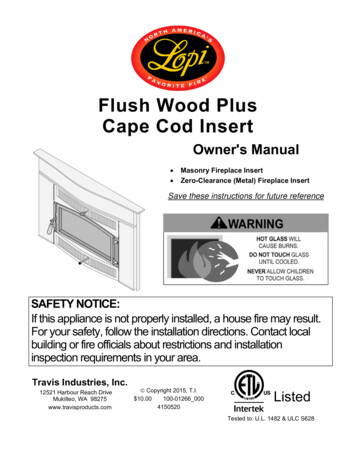
6Stove Installation (for qualified installers only)Installation OptionsFeatures Masonry Fireplace Insert 2.2 Cubic Foot Firebox VolumeZero-Clearance (Metal) Fireplace Insert Single Operating Control Accepts Logs Up to 24" Long Steel Plate Construction (Up to 5/16") Heavy Duty Refractory FirebrickStandard High-Tech Blower Heating SpecificationsApproximate Maximum Heating Capacity (in square feet)*Maximum BTUs per Hour (Cord Wood Calculation)Maximum Burn Time1,200 to 2,00073,300Up to 10 Hours* Heating capacity will vary depending on the home's floor plan, degree of insulation, and the outsidetemperature. It is also affected by the quality and moisture level of the fuel.This model was not tested for efficiency however it is assigned a default efficiency of 63% by the EPAunder previous subpart AAA. Efficiency of this wood heater will be affected by the operational burn rateand the moisture content of the wood used as fuel.Dimensions500 Lbs. (222Kg)6" (153mm) Dia.28-7/8" 61mm)17-3/4"(451mm)2-1/2”(64mm)aFigure 1(a) Fireplace OpeningEmissionsThis heater meets the 2015 U.S. EPA’s crib wood emission limits for wood heaters sold afterMay 15, 2015. Tested to Method 28, 5G1 this heater has been shown to deliver heat at ratesranging from 12,100 to 29,600 BTU/hr and an emission value of 4.4g/h. Travis Industries100-01266 0004150520
Fireplace Insert Installation (for qualified installers only)7SAFETY NOTICE:Please read this entire manual before you install and use your new room heater. Failure tofollow instructions may result in property damage, bodily injury, or even death. Contactlocal building or fire officials about restrictions and installation inspection requirements inyour area.Planning The InstallationWe suggest that you have an authorized Travis Industries dealer install your fireplace insert. If youinstall the fireplace insert yourself, your authorized dealer should review your installation plans.Check with local building officials for any permits required for installation of this fireplace insert andnotify your insurance company before proceeding with installation.The location of your wood heater in your home will decide how affectively the heat produced will spreadthroughout your house. Attention to the home design with consideration of natural convection and aircirculation should be taken into account when choosing the placement of your heater within the home.Preparation for Installation Check for damage to the exterior of the fireplace insert (dents should be reported, scratches can be fixed byapplying touch up paint).Check the interior of the firebox (replace cracked firebrick and make sure baffle is in place).The fireplace insert can be lightened by removing the firebricks and baffle (pg 34) - replace before operation.Installation ConsiderationsInstallation TypeConsiderationsInsert with Positive Flue (Full Reline) – Required in Canada(Page 17) Utilizes existing masonry or zero clearance fireplace Provides best draft Easiest to clean Masonry fireplaces only Provides good draft Requires fireplace block-off plate - see page 17Insert with Direct Connect Flue (Page 17)NOT APPROVED IN CANADAAdditional Requirements for Canada Do not remove bricks or mortar from existing fireplace. This fireplace insert must be installed with a continuous chimney liner of 6” diameter extending from the fireplaceinsert to the top of the chimney. The chimney liner must conform to the Class 3 requirements of CAN/ULC-S635,Standard for Lining Systems for Existing Masonry or Factory-Built Chimneys and Vents, or CAN/ULC-S640,Standard for Lining Systems for New Masonry Chimneys. Permanently seal any opening between the masonry of the fireplace and the facing masonry. Fireplace insert, or surround panels, may be removed to inspect fireplace insert and fireplace.Ash GuardThe included ash guard prevents ash from exiting the door opening.It is shipped detached to prevent damage during shipping. Travis Industries100-01266 000Install the ash guard as shown below. Note how thehorizontal tab fits in front of the door opening.4150520
8Fireplace Insert Installation (for qualified installers only)Fireplace RequirementsFigure 2 shows the minimum size requirements for the type of fireplace used.CombustibleMaMinimumFireplace SizeMasonryFireplaceZ.C. (Metal)FireplaceaHeight (front)21.5"547mm21.5"547mmbHeight (rear)19.75"502mm19.75"502mmcWidth (front)30.875” *(785mm)30.875” **(785mm)dWidth (rear)18.875”(480mm)20.875” **(531mm)eDepth ***17.75”(451mm)18.75" **(477mm)df Hearth Depth(includes insertdepth on hearthplus requiredhearth extension)17.25"439mm (US)-----------19.25”489mm (Canada)17.25"439mm (US)-----------19.25”489mm (Canada)egHearth Width44.875"1140mm44.875"1140mmhFacing Width46.875"1191mm46.875"1191mmiFacing Height39"991mm39"991mmjMantel bFacingaNocn-CombustibgleHearthfFigure 2* Includes 2”(51mm) for power cord installation.** 1” (26mm) Clearance to fireplace walls is required for ZC Fireplaces.*** Add 1.25” (32mm) when using one-piece panel (FW Rectangle Only)Fireplace Altered TagAttach the "This fireplace has been altered." plate to the fireplace (use two screws or other suitablemethod). You may wish to place it in a location where it will be covered by the surround panels. Travis Industries100-01266 0004150520
Fireplace Insert Installation (for qualified installers only)9Insert Placement Requirements The insert must be placed so that no combustibles are within, or can swing within (e.g. drapes,doors), 36" (915mm) of the front of the insert (Figure 3 “q”). Insert and hearth must be installed on a level, secure floor The minimum clearances, facing, and hearth requirements in Figure 3 must be met. Follow theclearances for the type of fireplace being used – (masonry or yFireplaceZ.C. (Metal)Fireplacek Sidewall9"229mm9"229mml Side Facing(noncombustible)9"229mm9"229mmm Top Facing(noncombustible)39"991mm39"991mmn Mantel(combustible)41.5"1055mm41.5"1055mmo Front Hearth(does notinclude insertextension “x”)16"407mm (US)----------18”458mm(Canada)16"407mm (US)----------18”458mm(Canada)p Side Hearth8"204mm8"204mmq Front of Insert36"915mm36"915mmx Extension OntoHearth1.25"32mm1.25"32mmpNoqn-CoHe mbuart stih blexoFigure 3Hearth Requirements Must extend 16" (USA) or 18” (Canada) in front of the insert and 8" on both sides. Must be non-combustible and at least .018" thick (26 gauge)Masonry Fireplace Requirements Chimney must have a clay tile liner or a stainless steel liner (positive connection). Entire fireplace, including chimney, must be clean and undamaged. Any damage must be repairedprior to installation of the insert. Chimney height: 15' (4.5M) minimum; 33' (10M) maximum (measured from base of insert). Entire fireplace, including chimney, must meet local building requirements. The fireplace insert must be placed on a masonry hearth built to UBC standards. Travis Industries100-01266 0004150520
10Fireplace Insert Installation (for qualified installers only)Zero-Clearance (Metal) Fireplace Requirements Must be manufactured by one of the following manufacturers: Marco Majestic Heat N Glo Heatilator Lennox Martin Preway Tempco Superior MonessonEntire fireplace, including chimney, must meet local building requirementsChimney height: 15' minimum; 33' maximum.The damper ("A") and grate ("B") must be removed (see illustration below). The smoke shelf ("C"),internal baffles ("D"), screen ("E"), and metal or glass doors ("F") may be removed (if applicable).The masonry lining ("G"), insulation ("H"), and any structured rigid frame members (metal sides, floor,door frame, face of the fireplace, etc. – "I") may not be removed or alteredHACFDIEB GThe chimney on the ZC fireplace must be listed per UL 127 or ULC 610-M87 for all installations. Anythermal protection component of the fireplace or chimney must remain in place. The fireplace andchimney must be inspected prior to installation. A NFPA 211 Level II inspection is recommended.Repairs must be made prior to insert installation. The base of the fireplace must be structurallysound and able to support the weight of the insert.The stainless steel liner must be 6” diameter and extend the full height of the chimney (also called apositive connection or full re-line). This liner must meet type HT (2100 F) requirements per UL 1777(USA) or ULC S635 with “0” clearance to masonry (Canada). The liner must be attached to the insertflue collar and to the top of the existing chimney.We recommend using the listed Travis ZC Liner Kit from Duravent (SKU 98900046, 47, or 48). If youdo not use this kit, you must use the original ZC chimney cap.The liner support and cap at the top of the chimney must not reduce air flow for the existing air-cooledchimney system. The Travis ZC Liner Kit includes a cap that meets this provision.To prevent air from passing up the ZC fireplace chimney (the gap between the liner and chimney) werecommend sealing the area near the damper. Use non-combustible material to seal this area (nonbacked fiberglass insulation or kaowool).The convection air channel on the fireplace must not be blocked. Do not block any louvers, grills, orair passages on the front of the fireplace.Entire fireplace, including chimney, must meet local building requirements. Permits may be requiredfor installation. Final approval is contingent upon the authority having local jurisdiction. Inform youinsurance agent of this fireplace insert.Drafting PerformanceDraft is the force which moves air from the appliance up through the chimney. The amount of draft in yourchimney depends on the length of the chimney, local geography, nearby obstructions and other factors.Too much draft may cause excessive temperatures in the appliance and may damage the heater.Inadequate draft may cause backpuffing into the room and plugging' of the chimney. Inadequate draftwill cause the appliance to leak smoke into the room through appliance and chimney connector joints. Anuncontrollable burn or excessive temperature indicates excessive draft. Travis Industries100-01266 0004150520
Fireplace Insert Installation (for qualified installers only)11Insert RollersTwo rollers are built into the back edge of the insert. Thisallows the insert to be rolled into position by lifting the frontof the insert and pushing it into position (see Figure 4).Figure 4Leveling Bolt InstallationMASONRY NOTE: Place a metal plate below thebolts on masonry fireplaces to prevent damage to thefloor brick.Two leveling bolts are pre-installed on the insert toallow for proper leveling within the fireplace. Toaccess the bolts, remove the back corner firebricksand cover plates (see Figure 5 “a” and “b”) The boltsare pre-threaded to a weld-nut on the base of theinsert. Use a 3/4” socket wrench to screw the boltsdown (clockwise) until the insert is level (see “c”).bcaSEALING THE COVER PLATE: We recommendsealing the cover plate with furnace cement (place onunderside of cover plate).BOLT LENGTH: The included bolts allowapproximately 1” of rise. If additional rise is required,use a longer 1/2-13 thread bolt. Make sure theadditional bolt length does not interfere with the coverplate.Figure 5Flue InstallationRLH Chim-Flex Starter SectionsFlue (flexible or rigid)Included in the owner’s pack arethree “flue brackets” and six selfdrilling screws. Use thesecomponents to secure the flue to theFlue Bracketfireplace insert.Self-Drilling ScrewsFlue Opening Travis IndustriesRLH manufactures startersections in straight orangled configurations tosuit your application.They are secured frominside the firebox, makinginstallation much easier.Contact RLH for additionaldetails:www.chim-flex.com100-01266 0004150520
12Fireplace Insert Installation (for qualified installers only)Cape Cod Face InstallationNOTE: The insert must be in position and connected to the flue before installing the face.1. Remove the bypass and air control rods from the insert as shown below.2. Route the power and rheostat wires to the side, as shown below.3. Lay out the sides and breastplate as shown below. Travis Industries100-01266 0004150520
Fireplace Insert Installation (for qualified installers only)134. Attach the sides and breastplate using the included bolts and washers, as shown below.NOTE: After tightening the bolt, back it off ½ a turn to allow the sides and breastplate to move slightly.5. Place the sides and breastplate near the insert. Connect the 2 rheostat wires, as shown below(orientation does not matter).6. Attach the sides and breastplate to the insert, making sure the two clips on each side slide over thetabs on the insert. Make sure the front is centered on the insert. Travis Industries100-01266 0004150520
14Fireplace Insert Installation (for qualified installers only)NOTE: Make sure the power cord is routed through the notch on the side and is not pinched or damaged.7. Attach the lower grill as shown below (the door must be open to attach).8. Replace the bypass and air control rods, as shown below.NOTE: You will need to reach into the firebox and hold the bypass yoke while attaching the bypass rod. Travis Industries100-01266 0004150520
Fireplace Insert Installation (for qualified installers only)15Place the mantel on top of the sides and breastplate, as shown below. Make sure it is centered, the clipsengage the side panels, and it is fully seated.The photo below shows the completed insert. Travis Industries100-01266 0004150520
16Fireplace Insert Installation (for qualified installers only)Re-Routing the Electrical Cord to the Left SideThe power cord is connected to the right side of the insert when it leaves the factory. It may be re-routedto the left side following the directions below. Do this procedure before installing the surround panels. Disconnect the molex connector and remove the power cord following the directions below.Disconnect the molex connectorleading from the power cord.Rheostat WiresPowerCordUse pliers to compress the strain relieffrom the top and bottom while pulling itout of the hole in the side of the insert.NOTE: An additional knockout isprovided if using the insert wiring kit.Route the power through one hole,the rheostat through the other.Leave the rheostatwires in place.Make sure the power cord isdisconnected prior toconducting these steps.Remove the power cord. Connect the power cord to the left side following the directions below.Attach the molex connector on thepower cord to the molex connectoron the left side of the insert.PowerCordRe-attach the strain relief to the left side (usepliers to compress the strain relief from the topand bottom while pushing it into the hole).Remove the button plug from the left side. Travis Industries100-01266 0004150520
Fireplace Insert Installation (for qualified installers only)Insert withPositiveConnectionInstall a non-combustiblecover plate to prevent waterfrom entering the chimney17Cap (prevents waterfrom entering)Flue LinerREQUIRED INCANADA.The liner must bestainless steelconnector or flexiblevent. Follow the linermanufacturer'sinsturctions forinstallation andsupport.Combustible MantleAirtight InsulatedClean-OutSurround PanelsRemove damperor wire it openSee the section "InsertPlacement Requirements" forminimum clearances andhearth required.Figure 6Insert with DirectConnection(MasonryFireplace)Stainless steel chimneyconnector must Extend 1'past the block-off plate or tothe flue linerFlueLinerNOT ALLOWED INCANADA.Combustible MantleA block-off plate orother non-combustiblesealing device (e.g.damper adapter) isrequired. It must sealthe chimney to insuresmoke does not enterthe home whileproviding the chimneysystem with sufficientdraft.AirtightInsulatedClean-OutSurround PanelsSee the section"Insert PlacementRequirements" forminimum clearancesand hearth required.Removedamperor wire itopenBlock-off plate ordamper adapterFigure 7 Travis Industries100-01266 0004150520
18Operating Your ApplianceSafety NoticeIf this appliance is not properly installed, a house fire may result. For your safety, follow the installationdirections. Contact local building or fire officials about restrictions and installation inspectionrequirements in your area.Read and follow all of the warnings on pages 4 and 5 of this manual.Before Your First FireVerify the InstallationBefore starting the stove, verify that the stove is properly installed and all of the requirements in thismanual have been followed.Keep all flammable materials 36" away from the front of the stove (drapes, furniture, clothing, etc.).Curing the Paint2 to 4 hoursFollow the steps below to cure the paint (first fire):a) Open doors and windows in the room to ventilate the heater during thecuring process.b) Vacate the room. The fumes from the initial heating process are non-toxicbut may be unpleasant.c) Slowly bring the heater to a medium burn (400 F/204 C) for 45 minutes.Then increase the burn temperature to a hot burn (600 F/315 C) for anadditional 45 minutes. This will cure the paint.Door Gasket - The door gasket might adhere to the paint on the front of theheater. Leave the door slightly ajar for the first fire and be careful whenopening the door after the first fire.Carbon Monoxide (CO) EmissionsSmoke from wood heaters contain CO. This gas is an indication of incomplete combustion and isdetrimental to the environment and to your health. The more visible the smoke, the higher the CO levels.Burning dry wood is the most significant step you can take to reduce CO emissions. It is also important tounderstand the combustion process so you can burn your heater efficiently. Read the manual thoroughlyso that you can operate your heater in the most efficient and clean manner possible.Over-Firing the StoveDO NOT OVERFIRE THIS HEATER: Attempts to achieve heat output rates that exceed heater designspecifications can result in permanent damage to the heater.This stove was designed to operate at a high temperature. But due to differences in vent configuration,fuel, and draft, this appliance can be operated at an excessive temperature. If the stove top or other areastarts to glow red, you are over-firing the stove. Shut the air control down to low and allow the stove tocool before proceeding.Over-firing may lead to damage of plated surfaces. If any portion of the heater glows red, it isconsidered over-firing and will void the warranty. Travis Industries100-01266 0004150520
Operating Your Appliance19Opening the DoorThe door becomes hot during use. Use a glove to open the door if the handle is hot.To prevent smoke from entering the room, open the bypass before opening the door (see followingpage for directions). You can also open the door a small amount and let air enter the firebox.Opening the DoorsRotate the handle up.Swing the door open.Closing the DoorsRotate the handle down to secureLift the handle and close the door. Travis Industries100-01266 000the door.4150520
20Operating Your ApplianceBypass OperationThe bypass controls the flow of smoke inside the heater. When pulled out, smoke goes directly up theflue, creating more draft. When pushed in, the smoke goes around the baffle, utilizing the secondarycombustion and making the heater more efficient. When starting or re-loading, pull the bypass out. During normal operation, push the bypass in.Us e the included pull toolto operate the bypas s rodB ypas s P ulled OutUs ed for s tarting and re-loadingB ypas s P us hed InUs ed for normal operation Travis Industries100-01266 0004150520
Operating Your Appliance21Starting a FireSince the dawn of time man has debated the best way to start a fire. Some use the boy-scout "tee-pee",some prefer th
Register your warranty online at: traviswarranty.com Save Your Bill of Sale. To receive full warranty coverage, you will need to show evidence of the date you purchased your heater. We suggest that you attach your Bill of Sale to this page so that you will have all the information you need in one place should the need for service or information