Transcription
CLAYTON STATE UNIVERSITY2000 CLAYTON STATE BLVDMORROW, GEORGIA 30260SPILL PREVENTION,CONTROL, ANDCOUNTERMEASURES (SPCC)PLANNovember 11, 2015rev. to contacts10/2018
Professional Engineer CertificationClayton State University’s Spill Prevention, Control, and Countermeasures (SPCC) Plan has beenreviewed and certified by a registered profession engineer, as shown below.I hereby attest that: I am familiar with the requirements of 40 CFR 112; I or my agent has visited and examined:Clayton State University2000 Clayton State Blvd.Morrow, Georgia, 30260 The SPCC Plan has been prepared in accordance with good engineering practice, includingconsideration of applicable industry standards, and with the requirements of 40 CFR 112; Procedures for required inspections and testing have been established; and The SPCC Plan is adequate for the facility.Professional Engineer: Jeffrey Weeber (Print or type name)Signature:PE Registration Number: 32278State: GeorgiaDate:
Table of ContentsSection 1 Introduction . 1-11.1 Purpose . 1-11.1.1 Applicability . 1-11.1.2 Responsibility . 1-11.2 Plan Administration. 1-21.2.1 Management Approval. 1-21.2.2 Location of the SPCC Plan . 1-21.3 Plan Review . 1-21.3.1 Amendment by the Regional Administrator . 1-21.3.2 Plan Amendments Due to Facility Changes . 1-21.3.3 Scheduled Plan Reviews. 1-21.4 Cross-Reference with SPCC Provisions . 1-31.5 Certification of the Applicability of the Substantial harm Criteria Checklist . 1-4Section 2 Facility Information . 2-12.1 Facility Owner, Address, and Telephone . 2-12.2 Facility Contacts . 2-12.3 Facility Operations, Layout, and Site Plan . 2-12.4 Facility Storage . 2-22.5 Drainage Pathway and Distance to Navigable Waters. 2-22.6 Spill History . 2-2Section 3 Potential Spill Predictions, Volumes, Rates, and Control . 3-13.1 Potential Discharge Volumes and Direction of Flow . 3-1Section 4 Discharge Prevention . 4-14.1 Drainage Control . 4-14.2 Practicability of Secondary Containment . 4-14.3 Inspections/Record Keeping . 4-14.3.1 Weekly, Monthly, and Quarterly Inspections . 4-14.3.2 Periodic Integrity Testing . 4-24.4 Personnel Training and Spill Prevention Procedures . 4-24.4.1 Personnel Instruction. 4-24.4.2 Designated Person Accountable for Spill Prevention . 4-24.4.3 Spill Prevention Briefings . 4-34.4.4 Site Security . 4-34.4.5 Flow Valves Locked . 4-34.4.6 Starter Controls Locked. 4-34.4.7 Pipeline Loading/Unloading Connections Securely Capped . 4-34.4.8 Lighting Adequate to Detect Spills. 4-34.4.9 Truck Loading and Unloading Operations . 4-34.4.10 Loading and Unloading Procedures Meet DOT Regulations . 4-4i
Table of Contents4.4.11 Secondary Containment For Vehicles . 4-44.4.12 Warning or Barrier System For Vehicles . 4-54.4.13 Vehicles Examined For Lowermost Drainage Outlets Before Leaving . 4-54.5 Brittle Fracture Testing. 4-54.6 Facility Drainage . 4-54.7 Bulk Storage Tanks/Secondary Containment . 4-54.7.1 Tank Compatibility with Its Contents . 4-54.7.2 Diked Area Construction and Containment Volume for Storage Tanks . 4-54.7.3 Diked Area, Inspection and Drainage of Rainwater . 4-64.7.4 Corrosion Protection of Buried Metallic Storage Tanks . 4-64.7.5 Corrosion Protection of Partially Buried Metallic Tanks . 4-64.7.6 Control of Leakage Through Internal Heating Coils . 4-64.7.7 Tank Installation Fail-safe Engineered . 4-64.7.8 Observation of Disposal Facilities for Effluent Discharge . 4-64.7.9 Visible Oil Leak Corrections from Tank Seams and Gaskets . 4-64.7.10 Appropriate Position of Mobile or Portable Oil Storage Tanks . 4-74.8 Facility Transfer Operations . 4-74.9 Spill Control Equipment. 4-74.10 Discharge Response and Countermeasure . 4-74.11 Discharge and Drainage Controls. 4-7Section 5 Discharge Response . 5-15.1 Spill/Discharge Response and Countermeasures. 5-15.1.1 Discovery of Spill/Release . 5-15.1.2 Minor Spill Response or Incidental Spill . 5-15.1.3 Major Spill Response / Spill Emergency . 5-25.2 Spill Reporting . 5-35.2.1 Federal Reporting Requirements . 5-35.2.2 State Reporting Requirements . 5-35.2.3 Spill Response Procedures . 5-35.2.4 Clean-Up of Spill Area. 5-35.3 Waste Disposal. 5-45.4 Discharge Notification . 5-45.4.1 Spill Investigation . 5-55.4.2 Written Reports . 5-55.4.3 Emergency Contact List . 5-5ii
Table of ContentsList of FiguresFigure 2-1: Site Vicinity Map . 2-3Figure 2-2: Site Layout – Oil Containing Equipment Locations . 2-4Figure 2-3: Site Layout – Oil Containing Equipment LKocations . 2-5List of TablesTable 1-1: Cross-Reference with SPCC Provisions . 1-3Table 2-1: Facility Contacts . 2-1Table 2-2: Facility Oil Storage . 2-6Table 2-3: Georgia Power Owned Transformers . 2-9Table 3-1: Spill Prediction Analysis . 3-2Table 4-1: Spill Response Equipment List. 4-8Table 5-1: Emergency Contacts . 5-6AppendicesAppendix A Plan Review and EvaluationAppendix B Certification of Applicability of the Substantial Harm Criteria ChecklistAppendix C Inspection ChecklistsAppendix D Spill Response and Reporting FormsAppendix E Georgia Power Transformer LetterAppendix F Rainwater Discharge Formiii
Section 1Introduction1.1 PurposeThis Spill Prevention, Control and Countermeasure Plan (SPCC Plan or Plan) was prepared byCDM Smith Inc. for Clayton State University (CSU) at 2000 Clayton State Blvd. in Morrow, Georgia.The purpose of the SPCC Plan is to describe the university’s operating practices intended toprevent potential spill events and to minimize the impact of any spills to human health and to theenvironment. In the unlikely event that an oil spill occurs, this Plan outlines facility responseefforts. This SPCC Plan is an update from the original SPCC plan prepared in 2011, andincorporates several revisions and additions that have occurred at the site since 2011.This Plan has been prepared to meet the requirements of Title 40, Code of Federal Regulations,Part 112 (40 CFR Part 112) – Oil Pollution Prevention. In addition to fulfilling regulatoryrequirements, this SPCC Plan is used as a reference for oil storage information, as a tool tocommunicate practices on preventing and responding to discharges with employees, as a guide tofacility inspections, and as a resource during emergency response.This facility is subject to the SPCC rule because it meets three criteria: It is non-transportation related. It has an aggregate aboveground storage capacity greater than 1,320 gallons. There is a reasonable expectation of a discharge into or upon navigable waters of theUnited States.1.1.1 ApplicabilityThis Plan applies to all work operations at our university where employees may be exposed topotential oil discharge situations under normal working conditions or during an emergencysituation.1.1.2 ResponsibilityThe Director of Facilities Management for CSU is responsible for developing and maintaining thisPlan and for making sure that the Plan is available to the EPA Regional Administrator for on-sitereview during normal working hours. Copies of the written Plan are located at Public Safety andare available twenty-four hours per day and seven days a week, and also at Facility Management.1-1
Section 1 Introduction1.2 Plan Administration1.2.1 Management ApprovalWe are committed to the prevention of discharges of oil to navigable waters and the environment.This Plan has the full approval of management at a level of authority to commit the necessaryresources to fully implement it.Responsible Officer: (Print or type name)Title:Signature:Date:1.2.2 Location of the SPCC PlanA complete copy of this Plan is maintained at the university with Public Safety and FacilityManagement. Normal operation hours for the office are Monday through Friday from 8am to5pm, however, the plan is available at any time at Public Safety. Public Safety can be reached atany time in the event of a spill. (Please refer to Section 2.2 for contact information).1.3 Plan Review1.3.1 Amendment by the Regional AdministratorIf this facility discharges (i.e. spills): (1) more than 1,000 U.S. gallons of oil in a single discharge, or(2) discharged more than 42 U.S. gallons of oil in each of two discharges, occurring within anytwelve month period, a written report must be submitted to the Regional Administrator of theU.S. EPA within 60 days. Refer to Section 5.4 for additional report information.1.3.2 Plan Amendments Due to Facility ChangesThe Director of Physical Plant will amend this SPCC Plan in accordance with Section 112.7 andother applicable Sections of Part 112, when there is a change in the facility design, construction,operation, or maintenance that materially affects its potential for a discharge. The amendmentwill be prepared within six months of the change. Examples of changes that may requireamendment to the Plan include, but are not limited to: Commissioning or decommissioning containers; Replacement, reconstruction, or movement of containers; Reconstruction, replacement, or installation of piping systems; Construction or demolition that might alter secondary containment structures; Changes of product or service; or Revision of standard operation or maintenance procedures at the facility.1.3.3 Scheduled Plan ReviewsThe Director of Physical Plant reviews this Plan at least once every five years from the datethe facility becomes subject to 40 CFR 112 and five years from the date of the last review.Amendments are then prepared within six months of the review. Any technical amendments to1-2
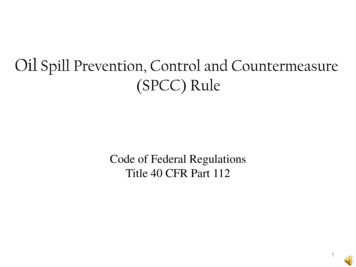
Section 1 Introductionthe SPCC Plan are certified by a professional engineer or self-certified. Self-certification ispermitted based on 10,000 gallons or less in aggregate aboveground oil storage capacity at CSU,and not having had (1) a single discharge of oil to navigable waters exceeding 1,000 U.S. gallonsor (2) two discharges of oil to navigable waters each exceeding 42 U.S. gallons. Certification is notrequired for non-technical amendments like changes to telephone numbers, names, etc. The planreview dates and certifications (as necessary) are included in Appendix A.1.4 Cross-Reference with SPCC ProvisionsThis SPCC Plan does not follow the exact order presented in 40 CFR Part 112. Section headingsidentify, where appropriate, the relevant sections of the SPCC rule. The following table (Table 11) presents a cross-reference of the Plan sections relative to applicable parts of 40 CFR Part 112.Table 1-1: Cross-Reference with SPCC ProvisionsRegulation SectionRegulatory RequirementLocation in SPCC112.3(d)Professional Engineer certificationPage 1112.3(e)Location of SPCC PlanSection 1.2.2112.5Plan reviewSection 1.3112.7Management approvalSection 1.2.1112.7Cross-Reference with SPCC RuleSection 1.4112.7(a)(3)General facility information, site plan, andfacility diagramSection 2Figures 2.1, 2.2, and 2.3112.7(a)(4)Discharge notificationSection 5.4Table 5-1112.7(a)(5)Discharge responseSection 5112.7(b)Potential discharge volumes and directionof flowSection 3Tables 2.2 and 3.1Figures 2.2 and 2.3112.7(c)Containment and diversionary structuresSection 4.7112.7(d)Practicability of secondary containmentSection 4.2112.7(e)Inspections, tests and recordsSection 4.3112.7(f)Personnel training, and dischargeprevention proceduresSection 4.4112.7(g)SecuritySection 4.4.4112.8.bFacility drainageSection 4.6Bulk Storage Containers / SecondaryContainmentSection 4.7112.8(c)(6)InspectionsSection 4.3Appendix C112.8(c)(7)Leakage controlSection 4.4 and 4.7112.8(c)(8)Overfill prevention systemSection 4.7.7112.8(c)(9)Effluent treatment facilitiesSection 4.7.8112.8(c)(10)Visible dischargesSection 4.7.9112.8(c)(11)Mobile and portable containersSection 4.7.10Transfer operations, pumping, and inplant processesSection 4.4.9Section 4.8112.8(c)(1-5)112.8(d)1-3
Section 1 Introduction1.5 Certification of the Applicability of the Substantial harmCriteria ChecklistSection 112.20(e) of the facility response plan regulation requires that all facilities regulated by40 CFR Part 112 conduct an initial screening to determine whether they are required to develop afacility response plan. The criteria in this checklist can be found in 40 CFR 112.20(f)(1) and isincluded in Appendix B.1-4
Section 2Facility Information2.1 Facility Owner, Address, and TelephoneThe facility owner name, address, and telephone number is as follows:The Board of Regents of the University System of Georgia270 Washington Street, S.W.Atlanta, GA 30334(404) 657-7099The facility operator name, address, and telephone number is as follows:Clayton State University2000 Clayton State Blvd.Morrow, GA 30260(678) 466-4050(404) 961-35402.2 Facility ContactsFacility contact(s) in case of a spill include the following:Table 2-1: Facility ContactsContact NameAntonio LongBobby Hamilas of 9/18Darren ThomasLana Soroka Cindy Knightas of 6/18Priti BhatiaHarun BiswassTitleWork NumberHome or AlternateNumberDirector of Public SafetyDirector of PhysicalPlantEHS(678) 466-4050(678) 466-4240(770) 961-3540(404) 520-3490Assistant DirectorFacilities ManagementAssistant Vice President ofFacilities Management(678) 466-4203678-466-4244(678) 466-4240(470)848-31462.3 Facility Operations, Layout, and Site PlanThe physical layout of the facility is presented in Figure 2-1 and Figure 2-2, a site vicinity mapand a facility map, respectively, for the campus and the apartment complex, Clayton Station.2-1
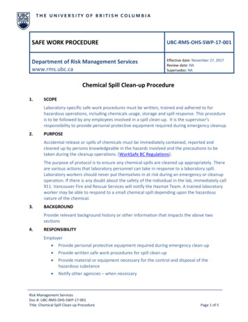
Section 2 Facility Information2.4 Facility StorageCSU is a higher-education facility that contains low quantities of used oil and fuel, as well asequipment that includes an oil storage reservoir in which the oil is present solely to support thefunction of the device. The university also has elevators, diesel emergency back-up generators,and transformers.All storage containers or equipment regulated under the SPCC rule are listed in Table 2-2 andTable 2-3. The elevator reservoirs are in rooms that act as secondary containment. Transformers are stored on the ground surface or on the utility post (i.e. Clayton Station). The aboveground storage tanks (ASTs) are located at the facility maintenance area. Theused oil AST is on a concrete floor and is under cover. The unleaded gasoline AST is locatedoutside and on concrete. The diesel fuel AST is located under cover on a spill pallet undercover. The used oil and gasoline ASTs are both double walled. The two diesel emergency generators are located within secondary containment structuresthat can contain more than 110% each generators respective diesel fuel storage capacity.The capacities of containers present at the university are listed in Table 2-2 and Table 2-3 andare also shown on the facility diagrams (Figure 2-2 and Figure 2-3). Only containers containing55 gallons or more of oil are included, except for one transformer whose capacity was reported asan average. Because this transformer may contain more than 55 gallons of oil, it was included.Oil-filled Equipment and Reservoirs less than 55 gallonsCSU also operates equipment containing less than 55 gallons of oil such as certain elevators andtrash compactors. These are not listed in Table 2-2.2.5 Drainage Pathway and Distance to Navigable WatersThe CSU Facility is located in Clayton County, Georgia. The storm water from this university flowsto drainage ditches and storm water drains and then to the Swan Lake, located on the south of thesubject site. Figure 2-1 shows the topographic map and drainage pathway for the area.Equipment that contains oil within the university buildings are not located near any floor drainsthat empty into the storm sewer, but some transformers located outside are. In the event of aspill, the oil will be cleaned up using absorbents and booms. If any oil enters the drain, plantpersonnel will notify the Clayton County Water Authority and other appropriate agencies (Table5-1).2.6 Spill HistoryAny spills are documented on a spill log (Appendix D), located in the EHS/Property RiskCoordinator’s office. At the time of the creation of this SPCC Plan, the facility has not experiencedany spill events within the past ten years that exceed 42 gallons.2-2
Table 2-2: Facility Oil StorageBuilding Name/ContainerLocationTank/Container TypeIDOwnerAbove Ground StorageTankAST-1CSUUsed Oil250AST-2CSUUnleaded Gasoline500AST-3CSUDiesel Fuel110Elevator (Freight)E-1CSUHydraulic Fluid100Elevator (Passenger)E-2CSUHydraulic Fluid100Spivey HallElevator (Passenger)E-3CSUHydraulic Fluid100Spivey HallSpivey HallElevator (Freight)Elevator (Stage Lift)E-4E-5CSUCSUHydraulic FluidHydraulic Fluid100250Music EducationElevator (Passenger)E-6CSUHydraulic Fluid105Student Activity CenterJames M. BakersUniversity CenterJames M. BakersUniversity CenterJames M. BakersUniversity CenterElevator (Passenger)E-7CSUHydraulic Fluid150Elevator (Passenger)E-8CSUHydraulic Fluid300Elevator (Passenger)E-9CSUHydraulic Fluid300Elevator (Freight)E-10CSUHydraulic Fluid425LibraryElevator (Passenger)E-11CSUHydraulic Fluid200LibraryElevator (Freight)E-12CSUHydraulic Fluid200Clayton HallElevator (Passenger)E-13CSUHydraulic Fluid125Arts and SciencesElevator (Passenger)E-14CSUHydraulic Fluid70Student CenterElevator (Freight)E-15CSUHydraulic Fluid80Student CenterElevator (Passenger)E-16CSUHydraulic Fluid100Laker HallElevator (Passenger)E-17CSUHydraulic Fluid100Annex-LABCSU-EastAdministration Bldg.CSU-EastMulti-purpose Bldg.Elevator (Passenger)E-18CSUHydraulic Fluid80Elevator (Passenger)E-19CSUHydraulic Fluid80Elevator (Passenger)E-20CSUHydraulic Fluid80Facilities ManagementFacilities ManagementFacilities ManagementHarry S. Downs Center(School of Nursing)Harry S. Downs Center(School of Nursing)Above Ground StorageTankAbove Ground StorageTankContentsTotalCapacity(gallons)Page 1 of 3Secondary ContainmentDouble Walled Tank. Inside spill containment berm. Located under coverDouble Walled Tank. Active spill containment measures stationed adjacent totank. Discharge would pour onto concrete pad and flow toward the storm drainadjacent to the tankOn spill pallett and located under coverInside Locked Room. Building floor is Secondary Containment. Concrete floorsand walls.Inside Locked Room. Building floor is Secondary Containment. Concrete floorsand walls.Inside Locked Room. Building floor is Secondary Containment. Concrete floorsand walls.Inside Locked Room. Building floor is Secondary Containment. Concrete floorsand walls.Building floor is Secondary Containment. Concrete floors and walls.Inside Locked Room. Building floor is Secondary Containment. Concrete floorsand walls.Inside Locked Room. Building floor is Secondary Containment. Concrete floorsand walls.Inside Locked Room. Building floor is Secondary Containment. Concrete floorsand walls.Inside Locked Room. Building floor is Secondary Containment. Concrete floorsand walls.Inside Locked Room. Building floor is Secondary Containment. Concrete floorsand walls.Inside Locked Room. Building floor is Secondary Containment. Concrete floorsand walls.Inside Locked Room. Building floor is Secondary Containment. Concrete floorsand walls.Inside Locked Room. Building floor is Secondary Containment. Concrete floorsand walls.Inside Locked Room. Building floor is Secondary Containment. Concrete floorsand walls.Inside Locked Room. Building floor is Secondary Containment. Concrete floorsand walls.Inside Locked Room. Building floor is Secondary Containment. Concrete floorsand walls.Inside Locked Room. Building floor is Secondary Containment. Concrete floorsand walls.Inside Locked Room. Building floor is Secondary Containment. Concrete floorsand walls.Inside Locked Room. Building floor is Secondary Containment. Concrete floorsand walls.Inside Locked Room. Building floor is Secondary Containment. Concrete floorsand walls.
Table 2-2: Facility Oil StorageBuilding Name/ContainerLocationTank/Container TypeIDOwnerContentsTotalCapacity(gallons)Secondary ContainmentScience BuildingElevator (Freight)E-21CSUHydraulic Fluid180Inside Locked Room. Building floor is Secondary Containment. Concrete floorsand walls.Central PlantTransformer 2T-10CSUMineral Oil255No Passive Secondary Containment. Active Only. Spill would pool onto concretepad and then ground surface (grass) before going to storm drain or water body.Student Activity CenterLoading DockTransformerT-11CSUMineral Oil306No Passive Secondary Containment. Active Only. Spill would pool onto concretepad and then ground surface (grass) before going to storm drain or water body.Music Education LoadingDockTransformerT-12CSUMineral Oil355No Passive Secondary Containment. Active Only. Spill would pool onto concretepad and then ground surface (stones) before going to storm drain or water body.Student Center LoadingDockTransformerT-13CSUMineral Oil429No Passive Secondary Containment. Active Only. Spill would pool onto concretepad and then ground surface (grass) before going to storm drain or water body.UC Loading DockTransformerT-14CSUMineral Oil493No Passive Secondary Containment. Active Only. Spill would pool onto concretepad and then ground surface (grass) before going to storm drain or water body.Athletic and FitnessBuildingTransformerT-15CSUMineral Oil186No Passive Secondary Containment. Active Only. Spill would pool onto concretepad and then ground surface (grass) before goi
This SPCC Plan does not follow the exact order presented in 40 CFR Part 112. Section headings identify, where appropriate, the relevant sections of the SPCC rule. The following table (Table 1-1) presents a cross-reference of the Plan sections relative to applicable parts of 40 CFR Part 112. Table 1-1: Cross-Reference with SPCC Provisions