Transcription
Agile Product Lifecycle ManagementMCAD Connectors for Agile Engineering CollaborationUser GuideV 3.6.2.0Oracle Part Number – F17193-01March 2019
Copyrights and TrademarksIMPORTANT NOTICEThis document contains information protected by copyright.All rights are reserved, including the translation. No part of this documentation may be reproduced inany way (print, photocopy, microfilm or any other form) or processed, duplicated or distributed by use ofelectronic system without written permission of the company. The information contained in thisdocumentation does not constitute any obligation on the part of the seller. The software described inthis documentation is delivered under licensing contract which governs its use.XPLM Solution is not liable for errors in this documentation.All trademarks are the property of their respective owners.Contact Address (for Support Services see Preface chapter):XPLM Solution GmbHAltmarkt-Galerie Dresden, Altmarkt 25D - 01067 Dresden, Germanywww.xplm.comXPLM Solution Inc.250 Commercial Street, Suite 520Worcester, MA 01608 USA
MCAD User Guide 3.6.2.0CONTENTCopyrights and Trademarks . 2What is New in MCAD Release 3.6 . 8Toolbox and Library Part Support . 8Strict CAD Modification Workflow . 8Find Number Mapping for Creo Parametric . 8IDF Import (Creo Parametric only) . 8Starting the Agile PLM MCAD Connector . 8Menus and Toolbars . 9AutoVue Access from MCAD . 16Saving to Agile . 16Introduction . 16The EC Workspace . 16Using the Save Command . 17Checking In Design Structures . 26Multi-Select and Context Menus . 26Numbering Options . 29Accessing Agile Object via Links . 30Strict CAD Modification Workflow (ACW and ACE only) . 31Preferences Dialog. 33PLM Usage (PLM Mode) . 34Load Preferences . 34Activating and Deactivating the Load Preview Dialog . 36Save Preferences . 36Item and Publish Preferences . 37Class Preferences . 40Viewable Creation Preferences . 41Viewable File Creation Preferences . 41Property Value Preferences . 42Design Structures . 43Recursive Structures . 44Saving with Derived Files . 44Supported Viewable File Formats . 45Save with drawings . 46Save Session Command . 46Save with Configurations . 46Saving Commands Summary . 463
MCAD User Guide 3.6.2.0Feature Tree Context Menu Items. 47Quick View . 48“Check In/Incorporate”, “Check out” and “Cancel Checkout” . 48Status Information . 50Information Displayed by Structure Browser Nodes . 52File Sync Status Mismatch . 56Loading from Agile. 56Introduction . 56Using the Load Command . 58Load Dialog . 59Multi-Select and Context Menus . 63Structure Resolution Options . 66Creating New Objects . 68Introduction . 68Using the Create Object Dialog . 69Details Pane . 70Preferences Pane (initially collapsed) . 72Workspace Pane . 73Design and Item Properties Tables . 73Workspace Management . 74Introduction . 74Workspace name with Asian characters . 74Set Workspace During Load, Save or Object Creation . 75Archiving Complete Workspaces . 76CAD working directory vs. EC Workspaces . 77Workspaces on Save . 77Workspaces on Load . 79Workspaces on CAD Start . 80Using the Workspace Manager. 80Using the Workspace Manager CAD Session Tab . 80Multi-Select and Context Menus . 82Using the Workspace Manager Workspaces Tab . 84Search Field in the Workspace Manager . 85Multi-Select and Context Menus . 86File Sync Status Mismatch (Creo Connector Only) . 88Design File Release Process . 89Incorporating Design Objects . 89Assigning Design File Change Orders . 89Assigning File-Less Design Objects to Design Changes . 90Concurrent Engineering . 904
MCAD User Guide 3.6.2.0Design File Release Process . 93Strict CAD Modification Workflow . 93Known Issue for Solid Edge . 93BOM Publishing . 93Introduction . 94Overview of the BOM Publishing Process . 94Using the Save Command with Publish Options . 95Details of the BOM Publishing Process . 99Configurations and Family Tables . 101Change Process For Parts. 101Mapping Find Numbers to the PLM BOM . 101Toolbox and Library Parts (ACW and ACE Only) . 103Property Mapping . 104Introduction . 104Types of Mapping . 104CAD Thumbnail Support . 106Thumbnails for Part and Assembly Families/Configurations . 107CAD specific Functionality . 107Callback/User Exits in CAD Menu - Save As – Solid Edge . 107Handling of Part Families and Configurations . 107Numbering of Part Families and Configurations . 108Family Table Handling – Creo Parametric . 108Introduction . 108EC Web Connector User Interface (Design) . 108"Save Family Table" Command. 110External Reference Handling – Creo Parametric . 112Introduction . 112EC Web Connector User Interface . 112Support for Suppressed Components – Creo Parametric . 114Simplified Representations – Creo Parametric . 117Using Agile Find Numbers – Creo Parametric . 120CGR File Handling – CATIA V5 . 121Introduction . 121Functionality Overview – Datamodel . 121Changes to existing commands . 127Configuration Handling – SolidWorks . 128Introduction . 128Functionality Overview . 128Sample Configuration Handling . 129Customizing the Configuration Properties . 1305
MCAD User Guide 3.6.2.0Sample Master Configuration . 133SolidWorks and Solid Edge External References to Assemblies . 134Save As Override Functionality – Solid Edge. 135IDF Import – Creo Parametric . 136Web Conferencing with MCAD . 1376
MCAD User Guide 3.6.2.0PrefaceContacting Oracle Support ServicesFor Oracle Agile Engineering Collaboration support contact the Oracle Global Customer Support(GCS) via www.oracle.com/support or My Oracle Support via https://support.oracle.com.Accessibility of Code Examples in DocumentationScreen readers may not always correctly read the code examples in this document. Theconventions for writing code require that closing braces should appear on an otherwise emptyline; however, some screen readers may not always read a line of text that consists solely of abracket or brace.This documentation may contain links to web sites of other companies or organizations that xPLMSolution does not own or control. xPLM Solution neither evaluates nor makes any representationsregarding the accessibility of these web sites.7
MCAD User Guide 3.6.2.0What is New in MCAD Release 3.6Toolbox and Library Part SupportThe MCAD connector for SolidWorks now supports toolbox or library parts. This functionalityallows users to utilize the native toolbox/library part functionality of the CAD system whileretaining compatibility to the MCAD connector’s workflow. Refer the Toolbox and Library Parts(ACW and ACE Only) chapter for details.Strict CAD Modification WorkflowSince release 3.6, the MCAD connectors for SolidWorks and Solid Edge support a strictmodification workflow. This means, that CAD users are only allowed to modify PLM-known CADfiles in case that they also hold the check out in Agile PLM. For details, refer the Strict CADModification Workflow (ACW and ACE only) chapter for details.Find Number Mapping for Creo ParametricThe Transfer BOM find numbers functionality previously only available for the MCAD connectorsfor SOLIDWORKS and Solid Edge is now also available for Creo Parametric. Unlike thecorresponding functionalities for the other connectors, however, Transfer BOM find numbersrequires some configuration and also allows for additional customizing and BOM table layouts.Refer the Mapping Find Numbers to the PLM BOM chapter for details.IDF Import (Creo Parametric only)The MCAD connector for Creo Parmaetric now allows saving IDF files alongside the corresponding,imported Creo geometry files created by Creo’s IDF import functionality. The IDF files are saved toAgile as viewable files in this case. Refer the IDF Import – Creo Parametric chapter for details.Starting the Agile PLM MCAD ConnectorThe MCAD Connector for Agile PLM is operated from within your CAD system environment. Youradministrator provides you with a start-up command or icon that starts your CAD system with theMCAD Connector functions enabled.Not eIn order to use Engineering Collaboration you must be a registered Agile user.Starting with release 3.0, Engineering Collaboration MCAD connectors can work with the PLM8
MCAD User Guide 3.6.2.0Design data model only. This chapter describes the use of EC with the Design data model.Menus and ToolbarsWhen EC is enabled, you see an Agile menu in your menu bar, and optionally an Agile toolbar.Access to Engineering Collaboration functions is through this menu or toolbar.Table 1: EC Access Methods: According to the CAD SystemCAD SystemEC Access MethodAutoCADRibbon barCatia V5Toolbars and menuCreo ParametricMenu and toolbarInventorRibbon barNXMenu and toolbarSolidWorksMenuSolidWorks 2015and laterThe CAD vendor changed thebehavior of SW. Beginningwith version 2015, add-inmenus, such as the "Agile"menu, are displayed in the"Tools" sub-menuinstead of the root menu bar.Solid EdgeRibbon bar9
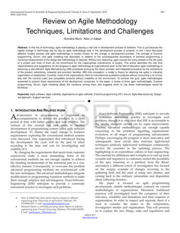
MCAD User Guide 3.6.2.0An example of both the Agile menu and toolbar is seen in the figure below:Figure 1: Example of both the Agile menu and toolbarThe figure below shows a sample for the CAD context menu directly embedded into the CADfeature tree:Figure 2: An example of the CAD context menu directly embedded into CAD.The contents and functions of the Agile menu and toolbar, which are common to all connectors,are shown in the table below.10
MCAD User Guide 3.6.2.0Table 2: Agile CommandsCommandSystemIconFunctionSearch in AgileAllOpens the Agile Web Client in Parametric Search mode inorder to find a design to load into CAD. Note that the loadfunction can be initiated directly from the web client using theLoad to CAD function.WorkspaceManagerAllOpens the Workspace Browser window. Displays checkout andrevision status of the current CAD model and all itscomponents. Also allows changing checkout status, andcreation and deleteting of different workspaces. If a PartFamily Generic is active in CAD, the status of the entire PartFamily table is displayed.SaveAllSaves files from the current CAD model and all its componentsinto Agile, with no save Preview dialog using default saveoptions.Save PreviewAllSaves files from the current CAD model and all its componentsinto Agile, with a dialog that allows the setting of save options.Save SessionAllSaves files from the current CAD session into Agile, with adialog that allows the setting of save options.Save FamilyTablePro/E, NXAllows the user to save an entire family table at once. WithPro/E, this process also validates the family table. The user isprompted if there are any errors with the validation processand a log file is created for review.Check OutAllPerforms a Check Out on the selected CAD objects in PLM. InSolidWorks and Pro/E the options are in the CAD contextmenu.Cancel Check OutAllCancels the Check Out on the selected CAD objects in PLM. InSolidWorks and Pro/E the options are in the CAD contextmenu.Check InAllSaves the current CAD model and its first level structure intoAgile. Components of the selected object are not saved. InSolidWorks and Pro/E the options are in the CAD contextmenu.11
MCAD User Guide 3.6.2.0CommandSystemIconFunctionShow Agile FormAllLaunches the Agile Web Client and displays the Agile formcorresponding to the current CAD model. In SolidWorks andPro/E the options are in the CAD context menu.Transfer BOMfind numbersSolidWorksSolid EdgeTransfers BOM table find numbers from drawing BOM tablesor drawing balloons to the BOM tab of the related model Itemin Agile. Some MCAD connectors do not support this functionfor drawing files with multiple references models and/ormultiple BOM tables.UpdatePropertiesAllSets property (attribute) values in CAD based on values fromAgile. Properties for the current CAD model and all itscomponents are updated. The specific attributes to map aredefined by your administrator in the configuration file.UpdateProperties First LevelAllSame as Update Properties, but only sets them for the currentCAD model and the next lower level (typically used for settingdrawing and model properties together).UpdateProperties CurrentAllSame as Update Properties, but only sets them for the currentCAD model.Update TitleBlockAllSets text values in the CAD drawing title block based on valuesfrom Agile. The specific attributes to map are defined by youradministrator in the configuration file.Quick ViewSolid EdgeOpens a popup dialog with the most important PLM-relatedinformation for the current CAD object. Also available in theCAD feature tree context menu, refer to chapter Quick Viewfor details.Open Native FileCATIA V5Opens the native CATPart or CATProduct files for the selectedCGR file(s).DisconnectSessionAllStarts (or re-starts) the EC Web Connector. Usually the WebConnector is started automatically on demand.AboutAllDisplays information about the current version of the CADConnector.12
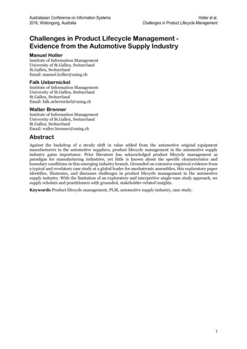
MCAD User Guide 3.6.2.0CAD Connector FunctionalityIn order to understand the details of the CAD Connector functionality, it is important tounderstand the overall process and how the data is stored in Agile. The figure below gives a highlevel view of the process.Figure 3: Agile Engineering Collaboration Process13
MCAD User Guide 3.6.2.0Figure 4: EC conceptOne important concept is that EC creates two distinct structures inside Agile, one is the DesignStructure, and the other is the Part BOM. Each of these is based on the CAD file structure that iscreated by the designer in the CAD system. The following table explains the purpose of each ofthese structures:Table 3: EC Structure typesStructure TypeData TypeHow CreatedPurposeCAD File StructureFilesCreated bybuilding CADmodels. Thestructure isknown within theCAD files.Defines the assemblystructure of CAD models.Also used to structure therelationships between CADdrawings and thecomponents on the drawing.Design StructureAgile Design object,with attached filesCreated using theEC Agile SavecommandManages the CAD fileswithin Agile, for saving andloading designs. The DesignStructure matches the CADfile structure on a one-forone basis.14
MCAD User Guide 3.6.2.0Structure TypePart BOMData TypeAgile Part objectHow CreatedCreated using theEC Agile Savecommand withpublish optionPurposeThe Part BOM representsthe physical product thatyou are going to build.When the Part BOM iscreated by EC, the Designobjects can be linked in avariety of ways to the PartBOM.To create and modify these structures in Agile, the CAD Connectors have three main functions –Save, Load and Workspace Manager. Each function has its own dialog window in the EC WebConnector. These functions are Save, Load, and Workspace Manager. These functions aredescribed in the following sections, followed by other miscellaneous functions.15
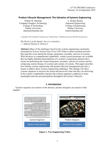
MCAD User Guide 3.6.2.0AutoVue Access from MCADMCAD dialogs now provide controls to directly access AutoVue. The AutoVue toolbar button whichis available in the CAD and Workspace tab of the Workspace Manager allows users to easily accessAutoVue displaying a certain CAD file, without having to access Agile PLM’s web client first.Figure 5: AutoVue Toolbar ButtonSaving to AgileIntroductionSaving into Agile, using the Agile Save command, creates a Design Structure in Agile. Thisstructure stores all CAD design files (Parts, Assemblies, Drawings, etc.) in a way that supports CADwork-in-progress design, and makes the data available to the rest of the organization, as privilegespermit. It saves the current CAD model (whatever is in the active CAD window), including all lowerlevel components.The EC WorkspaceWhen you work with Agile Engineering Collaboration you still have a local workspace directorywhere your CAD files reside. The location of this workspace directory is determined by yoursystem administrator. This is where files are copied to when you use the Load command. If youuse your CAD system’s File Save command, the files are saved into this workspace directory.You should use File Save to save periodically as you normally would, to prevent data loss duringyour daily work. Use the Agile Save command on a regular basis to secure your data withinAgile, and to make it available to others.16
MCAD User Guide 3.6.2.0Using the Save CommandWhen you execute the Agile Save
Oracle Part Number - F17193-01 March 2019 Agile Product Lifecycle Management MCAD Connectors for Agile Engineering Collaboration User Guide V 3.6.2.0