Transcription
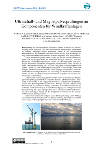
New and Innovative NonDestructive Testing (NDT)Techniques for Inspection andMonitoring of Metal SmeltingFurnacesAfshin Sadri, Pawel Gebski, KooroshMirkhani and Gordon McGarrieHatch Ltd.AbstractIn this paper, three (3) different NDT techniques areintroduced: Acousto Ultrasonic-Echo (AU-E), TapholeAcoustic Monitoring (TAM) and Ultrasonic pulse-echo(UT) for copper cooling element inspection. All three (3)techniques have been developed and implemented forapplications in metal smelting furnaces.The AU-E technique was developed to determine refractorythickness in operating furnaces. In addition, AU-E iscapable of determining metal penetration within furnacelining, determining position of cracks in the bricks anddelaminations within the sidewall and hearth lining.TAM is a monitoring system based on the acousticemission (AE) principals that is utilized to determine theremaining refractory thickness in tapholes, as the furnace isin operation.UT has been used to determine the remaining copperthickness in cooling elements in finger coolers, staves, platecoolers, breast coolers, and waffle coolers. To achieveaccurate measurements, a temperature correction factor forlongitudinal wave was used.Following a brief introduction to the above techniques,various applications and case studies will be discussed.IntroductionSmelting furnaces are the most volatile manmade structureswhich undergo severe thermo mechanical chemicaldeterioration and wearing. Molten metals and aggressivegasses are the main cause of vessel deterioration. To inspectand monitor the integrity of the metallurgical furnaces;elastic waves, including stress waves, ultrasonic waves andacoustic emission waves are the most reliable and practicalmeasuring systems. Based on the above NDT principals,various techniques have been developed to determine theintegrity of the refractory lining, vessel shell, tapholes andcooling elements.These techniques are Acousto ultrasonic-echo (AU-E)which uses stress wave reflection technique to assesrefractory thickness condition in operating furnaces;Taphole Acoustic monitoring system (TAM) which usesacoustic emission (AE) principals to monitor refractorywear in tapholes; and ultrasonic testing to monitor thicknessand integrity of copper cooling blocks that are installed onthe furnace sidewalls.Acousto UltrasonicTechnique–Echo(AU-E)Acousto Ultrasonic-Echo is a stress wave propagationtechnique using frequency data analysis. A mechanicalimpact on the surface of the structure (via hammer or amechanical impactor) generates a stress pulse propagatinginto the furnace layers. Where the impact head is sphericalor semi-spherical, it generates spherical waveforms whichare simple to analyze. The generated waves are broadbandand the diameter of the “impact head” dictates the range offrequencies: when the impact head is small the bandwidth ishigh frequency and when the impact head is large thebandwidth is low frequency.The waves are partially reflected by the change inrefractory layer properties, but the main energy propagatesthrough the solid refractory layers. The signal is mainlyreflected by the refractory/molten metal interface orrefractory/air interface between internal layers or externalboundaries. A receiver beside the impactor picks up surfacevertical displacements caused by reflections from internaland external reflectors. The vertical displacements aremainly reflected P-waves (or longitudinal waves) receivedby a sensor close to the impact source. The signals areanalyzed both in time and frequency domain, where thechanges in thickness and wave speed are the controllingfactors.In this methodology, the principal stress wave captured andanalyzed for quality assessment is the primary wave or theP-wave. Velocity of the P-wave varies form material tomaterial based on the density and elastic properties. Adrastic change in density and/or elastic properties of thematerial results in partial or total reflection of thewaveform.Two major elements are considered important in AU-Ecomputations. First, the shape and dimension effect of therefractory layers on the resonance frequency of the P-wave,which causes a change in wave speed. For the refractorylayers that are well bonded, the shape factor, , isconsidered used to correct the wave speed. For ametallurgical furnace the shape of the layers are either flator slab shape such as walls, or concave up or down, such aselectrical furnace hearth and roof; or circular or semicircular, like rotary kilns, converters and reactors. Second,since each layer contains bricks of different compositionand thickness, the wave speed in each layer and theirknown thickness must be taken into consideration in theoverall assessment of the furnace. The compressive or Pwave velocities are affected by the temperature. The effectof the temperature or -factor is unique for each type ofrefractory, for each range of temperature.The resonance of the P-wave arrivals to the surface causes aperiodic spectrum that can be best viewed by converting thetime-domain spectrum to a frequency domain using the fast
Fourier transform (FFT) technique. Equation 1 is thefundamental AU-E equation, where the T is the thicknessand fp is the frequency of the P-wave reflecting between thetwo interfaces.T VP2 fP(1)In the above equation, is the thermal correction for the Pwave speed and the factor is the shape factor correctionfor the P-wave speed. Equation 1 is correct when therefractory material is limited to a single brick or singlelayer. For multilayer refractory lining, the resonancefrequency of the P-wave is a result of the total (sum) ofresponses from each layer of the refractory lining. Thewaveform is affected by the material properties from eachlayer. Knowing the thickness of the layers are not changingon the cold face, using the frequency of the wave from thefull thickness and the known parameters, the thickness ofthe final layer is computed. Detection of frozen metal within hearth lining Taphole refractory thickness Detection of brittle zones in blast furnaces Cracks and delamination within refractory lining andindividual bricks Refractory qualification Identification of refractory hydration areasAll the above AU-E measurements are done as the furnaceis in operation.Furnace condition monitoring plans are organized to detectand foresee the lining issues prior to become an issueresulting in break-outs and metal run outs. The optimumplan is to conduct a baseline inspection after the firstfurnace start-up and later the same areas to be inspectedwithin a decided known time pattern. This type ofcondition monitoring will demonstrate the wearing anddeterioration pattern for the refractory lining and could beused as a predictive maintenance tool.Correct knowledge of both temperature and shape factors( and ) are important in computations of thickness andmaterial quality by the acousto ultrasonic-echo technique.The AU-E technique has been used for detection ofrefractory and accretion thickness in following vessels: Blast Furnace Electrical Arc Furnaces Six-in-Line Furnace Flash Smelting Furnaces Rotary Kilns ISASMELT Furnaces AUSMELT Furnaces Mitsubishi Process KIVCET Furnace Pierce Smith Converter Anode Furnaces Teniente/Noranda Reactors Tunnel Furnaces Reheat FurnaceIn addition to detecting refractory andthicknesses, AU-E has been used for detecting: Figure #1: The sensor and impactorarrangement on the shellaccretionMolten metal penetration within the lining layers infurnace oled tapblocks are essential components ofmodern smelting furnaces. Uninterrupted operation of a
tapblock is critical both for the structural integrity of afurnace and for the optimal operation and process control.This critical function together with the exposure to extremeconditions (thermal, chemical and mechanical) creates theneed for efficient and reliable means for tapblockmonitoring. A typical tapblock with and without therefractory inserts installed is shown in Figure2. The insideof the block is lined with refractory inserts, forming atapping channel, through witch the molten metal is tapped.These bricks wear out due to thermal deterioration and needto be replaced on regular basis. The water-cooled tapblockshave cast-in Monel pipes that serve as cooling circuits.These coils enable constant flow of water within the copperblock and in consequence they provide efficient means forthe heat exchange.caused by the motion of the molten material and by theresulting thermal expansion of the refractory. The elasticwave propagates through the refractory and copper, andthen approaches the cooling pipe. While both refractory andcopper significantly attenuate the signals, the Monel pipe isa good medium for propagation. The elastic wavespropagate through the Monel pipe towards the sensorsinstalled on the inlet and outlet. Since significantattenuation takes place while the signal propagates throughthe refractory and copper, the changes of the signal’sparameters will be related to the remaining thickness of therefractory lining and the copper. In general, the stronger thesignal, the less attenuation, hence there is less materialremaining. This concept is illustrated in Figure3.Figure #3: AE signal propagation pathwithin a tapblockFigure #2: Typical water-cooled tapblockremoved from a furnace:LEFT - with the refractory inserts installedright) without the refractory insertsPrinciples of the TAM SystemThe primary objective of the taphole monitoring systemwas to detect any wear and deterioration of the innertaphole refractory lining, with the ultimate objective ofidentifying any wear or shrinkage in the distance betweenthe copper element and the cooling Monel pipe. For thispurpose Acoustic Emission (AE) methodology was ic Emission is a powerful technique for evaluatingthe conditions of materials and structures. AE may bedefined as a transient elastic wave generated by the rapidrelease of energy within a material. This technique is usedto safeguard against catastrophic failures, to assessstructural integrity and to enhance safety in a wide range ofstructures. This is often combined with monitoring of themanufacturing processes. For the tapblock monitoring, theAE system was used to detect changes in refractory andcopper thickness and to evaluate their integrity.In this application, the primary source of the signals isrelated to the flow of the molten metal. The signals (AEevents) are generated on the interface between the moltenmetal and the inner refractory lining, and their occurrence isAs shown in Figure3 there are four components of theattenuation that should be considered for the tested tapblock(AR – attenuation within refractory, AC – attenuation withincopper, AMC – attenuation within the section of the Monelpipe that is cast in copper, AM – attenuation within theMonel pipe not cast in copper). The total attenuation of thesignal on its path from the source to the sensor is asummation of these components, see Equation2.A AR AC AMC AMEquation #2: Signal attenuation componentsFor the purpose of the refractory wear evaluation, out of thefour distinct attenuation components one is variable,namely: AR. The values of this component change when thethickness of the refractory changes. This relates back to thefoundation of this Taphole Acoustic Monitoring technique:reduced thickness results in less attenuation and strongerAE signals.PatternRecognitionEvaluation Based on AEforDamageIn order to process the large number of AE data in anefficient way, Hatch developed Pattern Recognitionsoftware. Using various combinations of signals’ features itis possible to identify the ones related exclusively orpredominantly to individual tapping events. This isschematically shown in Figure 4. Based on the experienceof the furnace operators it was later possible to assign the
most probable deterioration modes to those events. Thiswork, together with the signal source location, establishedbasics for the qualitative condition monitoring of tapblocksusing Acoustic Emission technique.Figure #4: Various events and the relatedAE signal parametersTAM SoftwareThe key software modules of the TAM system are: The Detection Module – including the data acquisitionsoftware. The Source Location Module – computing physicallocation of the tapping related signal sources. The Signal Processing Module – responsible for digitalfiltering of the acoustic signals. The Pattern Recognition Module – with learningalgorithms for recognizing the off-center lancing /tapping signal features.The TAM is continuously monitoring the tapping intensityat various areas of the tapping channel, relating it to therefractory deterioration. Selected screen captures from themonitoring software are shown in Figure 5.Figure #5: TAM software screen captures:LEFT – directional tapping control; RIGHT– detected area of high lancing intensityTAM Performance HistoryThe TAM system has been installed on two tapholes fortwo years. The main purpose of that installation was tomonitor the taphole refractory wear and to ensure that thecopper block remains intact. The system was validatedduring several minor tapping incidents. The data collectedduring these events was added to the knowledge base andused to recalibrate the alarms/warnings thresholds. TheTAM system has served its purpose well without any majorsoftware or hardware malfunctions. Several softwareupgrades were successfully conducted on-line, using theVirtual Private Network (VPN) connection.Cooler inspection using ultrasonic testingmethodMethodologyConsidering the critical role of the copper coolers, strictmonitoring of their performance is essential. Such amonitoring is accomplished by precise measurement of thecooler’s hot face thickness. Several non-destructive testingtechniques have been benchmarked for this purpose.Ultrasonic testing method is one of the promising methodsfor inspection of copper coolers. Por
metal and the inner refractory lining, and their occurrence is caused by the motion of the molten material and by the resulting thermal expansion of the refractory. The elastic wave propagates through the refractory and copper, and then approaches the cooling pipe. While both refractory and