Transcription
CENTURYNSD360ANSD-360A (SLAVED)NSD-1000 (SLAVED)COMPASS SYSTEMSPILOT’S OPERATING HANDBOOK10-01-9968S85
68S85FOREWORDThe NSD-360A and NSD-1000 families of instruments represent a significant break through inlow-cost compass and display systems. For maximum enjoyment, may we suggest that you dotwo things:1. Read this handbook.2. Spend some VFR flight time with the equipment to learn how to work with your autopilot andinstrumentation so that you may enjoy the convenience and benefits to the fullest.This handbook has been designed to provide operating techniques for the NSD-1000 and NSD360A when used with an autopilot such as the Century Flight Systems, Inc. Century IIB, III orAltimatic III series using the 1C388-2 radio coupler.These techniques apply equally to the NSD-360A and the NSD-1000 when used without autopilottie-in to provide more enjoyable and convenient manual flight. Of course references to the radiocoupler function should be disregarded.NOTEThis handbook may also be used with ARINC compass systems such as the PN-101, KCS-55A,etc., for operating techniques using the 1C388-3 ARINC radio coupler, provided the operatingdifferences and control location differences are properly noted.2
68S85CONTENTSForeword.1Introduction. .3NSA-360 .4NSD360A Description .5NSD1000 Description .6Operating Techniques .9Localizer (LOC) Approach .11Localizer Back Coures (LOC BC) Approach.15VOR Approach.19VOR Navigation .23Emergency Operation .24Maintenance .25Warranty. .263
68S85INTRODUCTIONAll versions have in common a servo’d heading card system to eliminate gyro drag and friction.This provides low drift performance in unslaved versions.The standard NSD-360A is the unslaved pneumatic version with a square front bezel for astandard 3 ATI instrument hole. Standard features include:1. VOR/Localizer left-right needle with Omni Course Resolver.2. Glideslope needle and flag.3. Internal lighting.Available NSD-360A options include:1. Slaving.2. RMI Bootstrap.The NSD-1000 (DC electric version) also features the ARINC square bezel (3 ATI) with thefollowing standard features:1. VOR/Localizer left-right needle with Omni Course Resolver.2. Glideslope needle and flag.3. Internal lighting.4. Slaving.Available NSD-1000 options include:1. RMI Bootstrap.The NSD-360A/1000 is designed to operate with external VOR/Localizer converters and RNAVequipment meeting and requiring ARINC needle and resolver characteristics.4
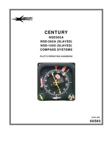
68S85Lubber LineAutopilot HeadingBugHeading eNeedleGlideslopeFlagNAV FlagGlideslopePointerCourse SelectorKnobHeading SelectorKnob/Card Set(push)NSD-360A5
68S85NSD-360AThe NSD-360A (Navigation Situation Display) is an integrated HSI instrument combining an airdriven gyro and an electrically servo’d heading card with VOR/Localizer and glideslopeinformation.NOTE:Do not set heading card when turning as the magnetic compassand magnetic flux detectors in slaved systems are not reliablereferences when the aircraft is banked.The NSD-360A has an optional slaving feature that requires initial heading setting on start-up.Subsequent resetting of the heading card, required manually on non-slaved versions, isautomatically accomplished.The NSD-360A has incorporated a heading warning flag to warn of loss of either air or electricpower. Appearance of the flag during flight should be sufficient grounds to question the validity ofdisplayed heading. In slaved versions, the slaving meter should oscillate about a 45 point toshow that the slaving circuits are accomplishing their function. Should the needle remainmotionless, vertical, or horizontal for an extended period (two minutes) in level flight, the headingshould be manually set so that the slaving meter is at the 45 point and then observe theperformance of the heading card. If slaving difficulties are encountered, set the slaving modeswitch to SL#2 or free gyro. In free gyro mode, the instrument must be periodically reset tomanually counteract the effects of gyro precession.6
68S85NSD-1000The NSD-1000 offers the same functions as the NSD-360A. The NSD-1000 incorporates anelectrically driven gyro. Appearance of the heading flag is to warn of loss of gyro speed or totalelectrical power loss to the instrument.NSD-360A and NSD-1000 CONTROLSThe heading selector/card set is used to move the heading bug relative to theheading card. It is also used to set the heading card to the aircraft headingby pushing in and rotating card. When setting has been accomplished theknob is released. The heading selector should not be pushed in when settingthe heading bug.The course selector knob is used to adjust the autopilot course selectorarrow to the desired course. Selection of the autopilot course automaticallysets the internal VOR resolver to the identical VOR radial. Readout of VORleft-right information is made by observing the center segment of the coursearrowDISPLAYSVOR/Localizer left-right deviation is display by the center segment of theautopilot course radio arrow. Note that the airplane in the center of theinstrument display gives a pictorial representation of the navigationsituation. In the illustration, the aircraft is approaching the desired radialat an approximate 20 intercept. When operating in the VOR mode, thedisplay always gives the correct display if the heading card is matched tothe magnetic heading. When operating in the localizer mode, the coursearrow should be placed on the INBOUND front course heading. Thedisplay will then be correct for either front course or back course.During back course approaches, the display will be inverted and the tail of the course arrow willindicate the back course heading. The left-right needle sensing will require turns toward theneedle for course centerline.7
68S85“TO” FLAG “FROM” FLAGThe TO and FROM flags point in the direction of the VOR station. TO Or FROM ispictorially represented. In the localizer mode, neither a “TO” or a “FROM” flag willappear. The same is true for either front or back course.NAV WARNING FLAGNAVThe red and white striped NAV warning flag will appear if the signal beingreceived is not suitable for NAVigation.GLIDESLOPE POINTERThe GLIDESLOPE meter on the left side of the instrument displays conventionalglideslope information - location of glideslope centerline is pictoriallyrepresented.The red and white striped GLIDESLOPE FLAG is on the left side of the instrument. It is arrangedso that it will obstruct view of the glideslope meter if a glideslope signal is not available or isunsuitable for guidance.IMPORTANT NOTICEIf the NSD360A/1000 is to be used in a shared display role ( i.e. indicating VHF NAV and RNAV orLORAN ), the incorporation of the Century Nav Data Selector is recommended.8
68S85NSD-360A and NSD-1000OPERATING TECHNIQUESIn the pages that follow we have included techniques for:Localizer ApproachesBack Course ApproachesVOR ApproachesVOR NavigationNOTEThese techniques are APPLICABLE to other compass systems such as the PN101, KCS-55A,etc., if the 1C388-3 radio coupler is used.9
68S85LOCALIZER APPROACH10
68S85LOCALIZER (LOC) APPROACHSee also Autopilot Manual for Glideslope Coupler TechniquesPSNNSD-360ANSD-1000RADIOCOUPLERThe localizer or ILS approach begins with atransition from the enroute structure to theouter compass locator (LOM). The radiocoupler is in the HDG position so the pilotmay control intercept location. The InboundFront Course direction is selected with thecourse arrow. Note: If a 45 intercept isdesired, the LOC REV position may beselected after radio course arrow ispositioned.1HDG2REMARKSAs the LOM is reached, select LOC REV onthe radio coupler. Coupler will intercept andtrack outbound.LOCREVAltitude for this phase of the approach iscontrolled using the Altitude or PitchCommand Mode. The outbound procedureturn heading may be preselected with theheading bug.3LOCREV45HDGSelect the HDG position on the radio couplerto begin procedure turn.HDGProceed outbound in procedure turn forsufficient time to assure proper reinterception.11
68S85LOCALIZER (LOC) APPROACH Con’tPSNNSD-360ANSD-1000RADIOCOUPLERREMARKS6Lead aircraft through procedure turn bymoving the heading bug initially about threefourths of the way around the card in thedesired direction of turn.7As the aircraft turns, move the heading bugto the 45 intercept heading. If intercept otherthan 45 is desired (radar vectored) selectintercept with HDG bug and delay selectionof LOC NORM.HDGHDGCAUTION: Glideslope coupler arming doesnot start until LOC NORM is selected.Approximately 20-30 seconds must elapsewith GS needle up for arming to occur.8Select LOC NORM—coupler will execute 45 intercept. Note: Some bracketing uponintercept is normal as coupler determinescrosswind; bracketing may be minimized byavoiding excess intercept speed.LOCNORM9LOCNORM10LOCNORMAfter intercept, coupler will compensate forup to 15 crosswind correction. Slightadditional crosswind correction for localizerapproaches may be achieved by movingcourse arrow to lubber line after initialcrosswind correction has occurred.If typical ILS glideslope coupling will occur asthe outer marker is reached. Extend gear andadjust power to maintain glideslope. Missedapproach may be pre-selected with headingbug.12
68S85LOCALIZER (LOC) APPROACH If missed approach is required, see AFMSupplement for correct procedures inyour model aircraft.13
68S85Localizer Back Course14
68S85LOCALIZER BACK COURSE (LOC BC)PSN1NSD-360ANSD-1000RADIOCOUPLERThe Localizer Back Course approachbegins with a transition from the enroutestructure to an intercept with the backcourse outbound. The Inbound FrontCourse is set on the course arrow and a45 intercept is achieved by selectingLOC Normal on the Radio Coupler.LOCNORMAlternate - If desired, the intercept maybe accomplished semi-automatically withthe HDG bug selecting the HDG mode onthe Radio Coupler. When automatictracking is desired, select LOC NORM onthe Radio Coupler.HDG1A2LOCNORM3HDG4HDGREMARKSAs outbound tracking begins, selectoutbound procedure turn heading withheading bug.When outbound procedure turn headingis desired, select HDG mode on RadioCoupler. Fly outbound for sufficient timeto permit proper re-interception.Lead aircraft through procedure turninitially by turning the heading bugapproximatelythree-fourthsdistancearound the card in the desired direction ofturn.15
68S85PSNLOCALIZER BACK COURSE (LOC BC) REV7LOCREV8LOCREV9As the aircraft turns, set heading bug toinbound procedure turn heading.For 45 intercept to back course inboundselect LOC REV on Radio Coupler. Note:Inbound Front Course direction must beunder course arrow or incorrect operationwill result.After intercept, Radio Coupler will correctfor up to 15 crosswind. If additionalcrosswind correction is needed move“Tail” of course arrow nearer lubber lineafter initial crosswind correction isaccomplished.During the LOC BC approach, altitude iscontrolled using the pitch command inautopilots so equipped.For missed approach, either remain onlocalizer or set heading bug and selectHDG on Radio Coupler as appropriate forprocedure.LOCREVORHDG16
68S85VOR APPROACH17
68S85VOR APPROACHPSNNSD-360ANSD-1000RADIOCOUPLERNAVThe VOR approach usually begins froman enroute situation.12345REMARKSAs the VOR is neared, match the headingbug to the lubber line and select HDG onthe Radio Coupler. The course arrowshould now be set for the Inbound VORradial (in the Illustration357 )HDGAs the VOR is crossed, select LOC REVON THE Radio Coupler to intercept andtrack the outbound VOR radial (177 ).LOCREVWhile the coupler is intercepting andtracking outbound, the outboundprocedure turn heading may be pre-selectwith the heading bug.LOCREVHDGTo begin the procedure turn, select HDGon the Radio Coupler.HDGProceed outbound until sufficient time haselapsed to assure proper re-interception.6This would be an excellent time torecheck the course arrow/OBS for theinbound course (in illustration 357 ).18
68S85VOR APPROACH KSHDGLead aircraft through procedure turn bymoving the heading bug initial aboutthree-quarters of the way around the cardin the desired direction of turn.HDGAs the aircraft turns, move the headingbug to the desired intercept heading.OMNISelect OMNI on the Radio Coupler for a45 intercept to the VOR course.After intercept, the radio coupler willcorrect for up to 15 crosswind; do notcompensate for excessive crosswind bymoving course selector . If a coursechange is required at the VOR for thefinal approach segment, simply move thecourse selector to the new course as theVOR is crossed. NOTE: Headingexcursions at the VOR may be minimizedby matching the heading bug to thelubber line and momentarily switching toHDG for station passage them returningto OMNI.OMNIFor missed approach, set heading bugand select HDG or OMNI as appropriatefor the approach procedure.HDG19
68S85VOR Navigation20
68S85VOR REMARKS45 intercept to a selected radial isautomatically accomplished by setting thecourse arrow/OBS to the desired courseand selecting NAV on the Radio Coupler.Alternate If desired ,a semi-automatic interceptis accomplished by setting the heading andselecting HDG on the radio coupler until thedesired course is neared and then selecting“NAV”.234NAVNAVNAVThe Radio Coupler will compensate for up to15 crosswind in the NAV mode. Note: Headingexcursions over VOR may be minimized bymatching the heading bug to the lubber line andmomentarily switching to HDG as the station iscrossed.If course changes are required at a VOR,simply reposition the course arrow/OBS to thenew course.Station switching is accomplished by rechanneling the NAV Receiver to the stationahead and repositioning the course arrow/OBSas required.If more positive course tracking is desired, OMNI may be used for VOR navigation if desired.NOTE: On extremely noisy VOR stations (those with nervous needles), it may not be possible toachieve comfortable tracking in NAV. The Radio Coupler cannot distinguish between needlemotion caused by noise and needle motion caused by valid course error information; it tries tofollow both. Under extremely noisy conditions, it may be desirable to revert to HDG and navigatecross-country with the heading bug.21
68S85EMERGENCY OPERATIONAppearance of HDG Flag:1. Check air supply gauge (vac or pressure) for adequate air supply (4 in. Hg min.)2. Check NSD-360A/NSD-1000 circuit breaker.3. Observe display for proper operation.To disable heading card – pull circuit breaker and use magnetic compass for directional data.Note: If heading card is not operational, autopilot should not be used.NSD-360A/NSD1000With card disabled -- VOR Localizer, and Glideslope displays are still functional; use card set torotate card to aircraft heading for correct picture.Slaving Failure - (i.e. failure to self correct for gyro drift):1. Check slave switch (if installed) for SL-1# PSN.2. Check for HDG Flag.3. Check NSD circuit breaker.4. Reset heading card while observing slaving meter.5. Select slaving amplifier #2 (SL-#2) if available.6. Reset heading card while checking slaving meter.7. Switch to free gyro and periodically set card as unslaved gyro.MaintenanceThe NSD family of instruments have been designed and manufactured to render reliable service.If service is required, it is important that agencies selected for service are properly qualified andequipped.Gyro Filter - The gyros used in the NSD-360A family areprecise devices whose performance and service life arein part dependent upon the quality of the air supply. Poorair quality can significantly reduce gyro life bycontaminating bearings. Regular filter maintenance is agood investment.22
68S85Effective: July 4, 1975LIMITED WARRANTY CENTURY FLIGHT SYSTEMS AUTOPILOTEach new Century Flight Systems Inc. Autopilot is warranted by themanufacturer to be free from defects in material and workmanshipunder normal use, subject to the following conditions:1. Century Flight Systems Inc. will through its designated servicefacilities at its option either repair or replace new componentswhich, shall within (12 months after date of installation, be found,to Century Flight Systems Inc. satisfaction, to have beendefective in material or workmanship under normal use.2. The warranty registration must be signed and returned to CenturyFlight Systems Inc. within ten days of equipment installationdate. In the event that the registration card is not returned withinthis time, the date of shipment from the factory will be deemed tobe the installation date.3. This warranty will not apply to any product which has beeninstalled, repaired or altered in any way whatsoever in CenturyFlight Systems Inc. opinion to adversely affect its performance orreliability, or which has been subject to misuse, contamination,negligence, or accident.4. Cost of transportation, removal or reinstallation are at the optionof Century Flight Systems Inc.5. This is Century Flight Systems Inc. sole express warranty withrespect to the goods supplied herein. CENTURY FLIGHTSYSTEMS INC. MAKES NO OTHER EXPRESS WARRANTYOF ANY KIND WHATSOEVER. CENTURY FLIGHT SYSTEMSINC.EMPLOYEES MAY HAVE MADE ORAL STATEMENTSABOUT THE PRODUCTS DESCRIBED IN THIS CONTRACT.SUCH STATEMENTS DO NOT CONSTITUTE WARRANTIES,SHALL NOT BE RELIED UPON BY THE CUSTOMER, ANDARE NOT PART OF THE SALE CONTRACT.6. THE DURATION OF ANY IMPLIED WARRANTY, AND OF ALLWARRANTIES OF MERCHANTABILITY AND FITNESS FOR APARTICULAR PURPOSE, SHALL BE LIMITED TO (12)MONTHS COMMENCING AT DATE OF INSTALLATION TOTHE FULL EXTENT PERMITTED BY APPLICABLE LAW,CONSEQUENTIAL DAMAGE OR BREECH OF ANYWARRANTY ARE HEREBY DISCLAIMED AND EXCLUDED BYCENTURY FLIGHT SYSTEMS.INC. .CENTURY FLIGHT SYSTEMS, INC.P. O. Box 610Mineral Wells, Texas76068January 198223
360A when used with an autopilot such as the Century Flight Systems, Inc. Century IIB, III or Altimatic III series using the 1C388-2 radio coupler. These techniques apply equally to the NSD-360A and the NSD-1000 when used without autopilot tie-in to provide more enjoyable and convenient manual flight. Of course references to the radio