Transcription
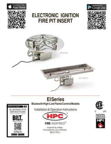
ELECTRONIC IGNITIONFIRE PIT INSERTPENTA24EI42X14SSEI-SEI SeriesBluetooth High/Low Flame Control ModelsInstallation & Operation Instructions860-EI HI/LOCUS
This is a Safety Alert SymbolWhen you see this symbol on the fire pit insert, or in this manual,look for one of the following signal word panels alerting you tothe potential for personal injury, death or major property damage.WARNING: For Outdoor Use Only.Installation and service must be performed by a qualifiedinstaller, service agency, or the gas supplier.WARNINGDo not store or use gasoline or other flammable vaporsand liquids in vicinity of this or any other appliance.An LP-cylinder not connected for use shall not be storedin the vicinity of this or any other appliance.DANGERFIRE OR EXPLOSION HAZARDIf you smell gas: Shut off gas to the appliance. Extinguish an open flame. If odor continues, leave the area immediately. After leaving the area, call your gas supplier or firedepartment.Failure to follow these instructions could result in fire orexplosion, which could cause property damage, personalinjury, or death.CARBON MONOXIDE HAZARDDANGERThis appliance can produce carbon monoxidewhich has no odor.Using it in an enclosed space can kill you.Never use this appliance in an enclosedspacesuch as a camper, tent, car or home.INSTALLER: Leave this manual with the appliance.CONSUMER: Retain this manual for future reference.1
Table of Contents1 Important Safety Information . 3Technical Support . 3Symbol Legend . 4Important Safety Information for Installers . 5Important Safety Information for End-Users. 62 Product Features and Parts List . 73 Selecting the Fire Pit Location . 84 Overhead Structures and Sidewall Clearance Requirements . 95 Fire Pit Enclosures Requirements . 116 Installing the Fire Pit .137 Adding Approved Media . 188 Operating the Fire Pit . 209 Maintaining the Fire Pit .2610 Troubleshooting . 2711 Wiring Diagram .2912 Compatible Accessories . 3013 Replacement Parts. 3114 Warranty . 322
1 Important Safety Information Hearth Products Controls Company recommends that our products are installedby professionals locally licensed by the authority having jurisdiction in gas piping.All installation instructions must be followed to ensure proper performance andsafety. Hearth Products Controls Company assumes no responsibility for problemsrelating to the installation. To qualify for warranty, all instructions must be strictly followed. Otherwise,warranty may be void. Never alter product or configuration in any way. Annual servicing should be handled by professionals certified in the US by theNational Fireplace Institute (NFI) as NFI Gas Specialists or in Canada by WETT(Wood Energy Technical Training). It is the installer’s responsibility to ensure a safe installation and to educate theend-user regarding the features, safety recommendations and proper operationof this product. Please reference page 1 for all warnings.INSTALLER:Leave this manual withthe appliance.END USER:Retain this manual forfuture reference.SELECT MODELSCertified toANSI Z21.97-2014CSA 2.41-2014CUSATTENTION:For the HPC Fire app,the default securitycode is:Technical SupportFor information and support contact your Hearth Products Controls dealer.32345
1 Important Safety InformationSymbol LegendThis is a Safety Alert SymbolWhen you see this symbol on the fire pit insert, or in this manual, look for oneof the following signal word panels alerting you to the potential for personalinjury, death or major property damage.IMPORTANTNecessary instructions4
1 Important Safety InformationPlease reference page 1 for all warnings.Important Safety Information for InstallersLeave this manual with the end-user and instruct them to retain it for futurereference. Instructions and product updates are also available at www.hpcfire.comunder the Support tab.Installers must carefully follow the instructions in this manual to prevent personalinjury or property loss. These instructions contain information critical to the safeinstallation and operation of the fire pit. Instructions are updated as needed. It is the responsibility of the installers tocheck for product updates and installation manual updates at www.hpcfire.com/support.html prior to installation. It is the responsibility of the installer to follow:- The National Fuel Gas Code, ANSI Z223.1/NFPA 54 or International Fuel Gas Code.- Natural Gas and Propane Installation Code CSA B149.1 or CSA B149.2.- The National Electrical Code, ANSI/NFPA 70. In Canada, Canadian Electrical Code CSA22.1.- Local codes Control options: Bluetooth technology only allows use with the supplied remotecontrol or a smartphone or tablet.Gas Only use the gas/fuel type specified for this fire pit, refer to the label on the fire pitcontrol box. Never use an alternative fuel to include biofuel, ethanol, lighter fluid orany other fuel. Gas pressure and type should be checked prior to use and installation.- Natural Gas Fire Pit: Required Supply Pressure: 7.0 inches W.C.- LP Gas: Required Supply Pressure: 11.0 inches W.C.IMPORTANTIf pressure is low, this will reduce flame height on HIGHsetting, possibly resulting in little to no flame variation.5
1 Important Safety Information If not using supplied flex line, ensure any flex line that may be used from thepermanent main fuel supply to the product is rated to the stated max BTU of theproduct and certified to ANSI Z21.75*CSA 6.27. The EI Series is not for use with small LP Tanks and must utilize permanent fixedpiping for fuel supply.Electrical Verify correct 120 VAC – 1 amp or 24 VAC – 4-amp power supply. Only use the typespecified for this fire pit. Refer to the label on the fire pit control box. All electronicapplications should utilize a GFCI-protected circuit.- If removing power cord plug and hard wiring within junction box, use only acertified Electrician and must follow the National Electrical Code (NEC), NFPA70 and all local codes.IMPORTANT24 VAC powered fire pit inserts:- Fire Pit will not perform properly if power supply rating isbelow 100W or wire size is too small.- HPC highly recommends using our HPC/Sebco 24 VAC100W power supply series (311-PS1, 311-PS3, 311-PS5Models)A Class II 24 VAC, 4-amp, 100 W transformer must be used to power the fire pitand be able to be switched on and off from a remote location to allow for easyaccess or emergency.- 24 VAC wire sizing: Wire lengths 75 ft or less: 14 gauge- Wire lengths 76 ft or more: 12 gaugeImportant Safety Information for End-Users Never leave an operating fire pit unattended or with someone not familiar withits operation or emergency shut-off locations. Both children and adults should be alerted to the hazards of high surfacetemperatures and should stay away to avoid burns and clothing ignition. Young children should be carefully supervised when they are in the area of fire pit. Keep the appliance area clear and free from combustible materials, gasoline,and other flammable vapors and liquids.6
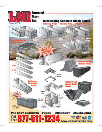
2 Product Features and Parts ListProduct FeaturesPanBurnerIgnition SystemBlowout BoxEI High/LowControl BoxAntennaExtensionParts List Fire Pit InsertAntenna Gas Input Flex Line – 24" Installation and OperationInstructions Remote Control (Bluetooth) &Antenna Extension CableAntenna BracketRemoteControl7
3 Selecting the Fire Pit LocationNOTE: All fire pits and systems are designed and intended for outdoor use only.IMPORTANTIt is recommended that material such as granite, marbleor other dense stone be kept away from heat andespecially flame due to risk of cracking. HPC is notresponsible for damage resulting from failure to followthese recommendations. Select a location that- ensures above-grade installation of the fire pit.- offers good drainage.- allows easy access for installation and maintenance of the fire pit.- provides enough horizontal room to enjoy the fire pit while allowing a safedistance from the heat and flame.IMPORTANTDeck installation — If installing fire pit on a woodor composite deck, it is required to use the DeckInsulation Kit(s) and locally bought paver stones.Kit includes basalt material and instructions.#FPI-DECK39SQ; #FPI-DECK20SQ. Also refer todrawing- Deck Insulation Kit- Install. Fire pits create very high temperatures. For clearances refer to table 3.1.Clothing or other flammable materials should not be placed on or near fire pit.Clearances around Fire PitFire Pit ClearancesUnder Valve Box when applicable for drainageUp to 200k BTU201k 400k BTU2"2"36" (12" fornoncombustible)Sides surrounding fire pit from structure or combustiblesOverhead clearance above product84"Table 3.1 – Fire Pit Clearances848" (24" fornoncombustible)Non-combustiblescreen only
4 Overhead Structures and Sidewall Clearance RequirementsIt’s important to review the clearance requirements below for any type of overheadstructure such as pergola, roof, overhang, screens, arbor, etc. or a sidewall to ensurethat the distances are met. Figures 4.1 and 4.2.Table 4.1 – Clearances for standard fire pit up to 200k BTU9
4 Overhead Structures and Sidewall Clearance RequirementsTable 4.2 – Clearances for standard fire pit up to 201k to 400k BTU10
5 Fire Pit Enclosures RequirementsLocation and design The enclosure must be installed above-gradeand allow for drainage to prevent waterdamage to fire pit.Figure 5.1 – Pan lip recessed on a trough. Refer to cut sheets on our website forimportant dimensional information for your fire pit. Visit www.hpcfire.com The fire pit assembly should be recessed a minimum of two inches from the topof the enclosure to protect flame from being blown out. It is recommended that material such as granite, marble or other dense stone bekept away from heat and especially flame due to risk of cracking. Manufactureris not responsible for damage. The enclosure must be constructed on a stable surface and be level. HPCrecommends the use of the installation collar (optional) that may be mortaredinto or sandwiched between layers of the enclosure. The weight of the fire pit must be supported by the pan and not by any control/valve box. HPC recommends that the pan lip is recessed on a trough (linear), and largeround enclosures, Figure 5.1.NOTE: HPC cannot guarantee the lip on all of our products will beperfectly flat and will not warp due to heat. There must be a minimum of 2 inches under the valve box for proper ventilationand drainage, see clearance drawings on page 9 an 10. The product must be accessible for service.Gas Fire pit must have a gas shutoff on the exterior of the fire pit to allow foremergency shut off and maintenance. The gas shutoff should NOT be used toadjust flame height. Fuel line sizing is the responsibility of the installer and must be able to supply thestated maximum BTU for the product – refer to product label on fire pit.11
5 Fire Pit Enclosures RequirementsConstruction materials Use non-combustible materials and construction for gas supply, powerand enclosure. The interior void space of the enclosure surrounding the valve boxcannot be filled with any material (gravel, crushed rock, concrete, etc.).Venting The enclosure must incorporate at least two vents to allow heat and or residual fuelto escape. Failure to properly vent the enclosure may result in the fire pit overheatingor explosion. Some enclosures may require more ventilation based on material, size, andextended use. The vent may also work as a drain when installed at bottom sidewall to preventwater build up. Vent specifications:- A minimum of two vents (18 square inches for each vent) on opposing sides ofthe enclosure totaling 36 inches of free area are required (example: 3-inch x 6inch or larger). Or, multiple vents uniformly made throughout the enclosuretotaling 36 square inches or more of free area are acceptable.- We recommend 4 vents total to reduce the risk of thermal shutdown.- Installation of the vents in the mid-to-lower area of the enclosure is recommended. Failure to properly vent the enclosure may result in the fire pit overheatingo r explosion. Continuous overheating could lead to heat damage tointernal components. When installing insert inside a non-HPC copper or concrete bowl, ventilationshould be below the bowl. If bowl is mounted on top of a column, a 6" hole isrecommended to allow gas supply, electrical and water plumbing to clear. OVERHEATING: the fire pit will automatically close the gas valve if the temperatureexceeds 190 F inside the valve box to prevent component damage. Turn mainpower to the fire pit off and on to reset. To correct overheating, ensure enclosurehas adequate ventilation per the guidelines in this section.12
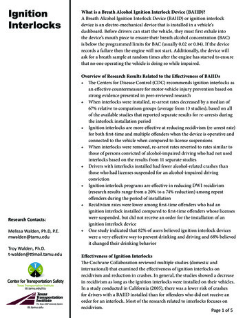
6 Installing the Fire PitIMPORTANTEnsure unit is set to proper gas type before installing fire pit into enclosure. If gastype is incorrect, follow steps below before continuing to Installation Steps:Gas Style Setting:1. Using a 2.5mm hex driver to loosen set screw on the back side of orifice and rotate collar. (For NG, ventureholes should be closed. For LP, venture holes should be open.)2. On the front side of orifice, use a #2 flat head screwdriver to rotate orifice from either NG to LP or LP to NGdepending on proper gas type. Always ensure that the colors for the orifice and collar are aligned.Set to NGSet to LPWARNINGORIFICE AND ALL FITTINGS MUST BE GAS LEAK CHECKED ANNUALLY BY AN NFICERTIFIED TECHNICIAN. SEE SECTION “9 MAINTAINING THE FIREPIT” ON PAGE 26FOR ROUTINE MAINTENANCE.13
6 Installing the Fire PitFuel line Fire pit must have a gas shutoff on the outside of the exterior of the fire pit to allowfor emergency shut off and maintenance. The gas shutoff should not be used toadjust flame height. The installer is responsible for using the correct fuel line sizing that can supply thestated maximum BTU for the product – refer to product label on the fire pit forspecifications.INSTALLATIONWe suggest that our products be installed by professionals that are locallylicensed by the authority having jurisdiction in gas piping. Perform all leak tests with leak detector or leak reactant.IMPORTANTTo prevent damage, unhook the fire pit from the gassupply for pressure leak tests of the supply line.IMPORTANTBurn Testing: It is the responsibility of the qualifiedinstaller to test for gas leaks at all connections.IMPORTANTGas Plumbing Connections: Use joint compound or tapethat is resistant to all gases. Apply joint compound only toall male pipe fittings. DO NOT use on flex line flaredfittings. Be sure to tighten every joint securely.Installation Steps:1. Set fire pit in properly constructed enclosure, read Section 5 – Fire Pit EnclosureRequirements.2. Position fire pit following safety recommendations with access to all gasconnections for testing. Read Section 3 – Selecting the Fire Pit Location formore details.3. Shut off gas supply to fire pit.4. Attach antenna extension cable as explained on page 15.5. Connect proper 120 VAC or 24 VAC electrical power following all local codes.6. Connect fire pit to main gas supply. Warning: avoid sharp bends with flex line toprevent whistling.14
6 Installing the Fire Pit7. Turn on gas supply, purge gas lines of air and perform leak test on all inletconnections. Repair as needed.8. Initial Start-up after install:Several “ON/OFF” cycles may be necessary to purge air in gas lines afterLED for flashsystem installation.count1. Turn “ON” electrical power to fire pit via wall switch or breaker.2. Turn “ON” gas to fire pit.3. Remove Blowout Box lid to allow viewing of hot surface igniter.4. Pointing remote control towards antenna, press and release the PowerHighON/OFF button, Figure 6.1.NOTE: Remote Control LED- 2 flashes indicates signal received.Low5. Hot surface igniter should begin to glow within 10 seconds.6. Pilot flame will eventually igniter. NOTE: This may take several cycles dueto air in the gas line. Unit will lockout after 15 cycles- to reset, please turn“OFF” electrical power using wall switch or breaker then turn “ON”,Figure 6.1 – Remote.repeat step 4.7. Main burner will igniter.Power On / Off8. Pointing remote control towards antenna- test High/Low function.IMPORTANTRemote Control LED- 8 or 10 flashes indicate signal notreceived. PLEASE CONFIRM ANTENNA IS MOUNTEDOUTSIDE ENCLOSURE AND ANTENNA/MINI-COAXCABLE CONNECTIONS ARE TIGHT, and then repeatsteps above.9. Once fire pit is lit, perform leak test on all gas connections. Repair as needed.IMPORTANTFor Penta Burner inserts, flame will be smaller with nomedia on the burner.10. Turn off fire pit and allow it to cool.11. Apply media as described in Section 7, Adding Approved Media. When fillingthe pan with lava rock and/or decorative glass, the instructions in Section 7 mustbe followed.12. Turn on fire pit again and perform leak test with media correctly installed. If gasleak is detected verify correct media application and repair as needed.13. Verify correct operation and lighting.14. Review safety manual with end-user. Instruct end-user that fire pit or media mustnot be changed or modified.15. Leave manual with end user.16. Apply the Start Up and Shutdown decal next to control box in an obvious andhighly visible position.15
6 Installing the Fire PitAntenna Extension Cable MountingFastener holesBegin by deciding where the antenna bracket will be installed, dependingon the type of enclosure, Figure 6.2. Antenna must be installed on the outside of the enclosure. Place antenna on side where most usage will occur. Install as high up on the enclosure but below top surface.Antenna holeFigure 6.3 – Plot the hole locationsFigure 6.2 – Antenna placementFigure 6.4 – Dry fit the bracketEnclosure with a cap1. Plot the hole locations that will be drilled to fasten the antennabracket. See Figure 6.3.NOTE: The two smaller holes are for fastening the bracket and the onelarger hole is for the antenna cable to slide through. When drillingholes, ensure there is no debris and that the antenna cable holeis large enough to not damage the antenna cable.2. Drill hole for antenna using the proper drill bits depending on thetype of finish on the enclosure.Figure 6.5 – Fasten down the bracket- The recommended hole size for the antenna is 3/8" (.375").3. After drilling, dry fit the bracket while sliding the antenna bracket intothe enclosure. Figure 6.4Attach- Mark holes for fastening bracket to enclosureantenna andcable here- Drill holes for fasteners4. Fasten down the bracket by using proper fasteners dependingon the type of finish on the enclosure, Figure 6.5.- Example: For brick finish use Tapcon screws.Figure 6.6 – Attach antenna cable5. Attach antenna to antenna cable with bracket asshown. Figure 6.6.16
6 Installing the Fire PitEnclosure without capFastener holes1. Plot the hole locations that will be drilled to fasten the antenna bracket.NOTE: The two smaller holes are for fastening the bracket and the onelarger hole is for the antenna cable to slide through. When drillingholes, ensure there is no debris and that the antenna cable hole islarge enough to not damage the antenna cable.2. Drill hole for antenna using the proper drill bits depending on the typeof finish on the enclosure.Figure 6.7 – Plot theAntennahole locationshole- The recommended hole size for the antenna is 3/8" (.375").3. After drilling, dry fit the bracket while sliding the antenna bracket into theenclosure. Figure 6.8.- Mark holes for fastening bracket to enclosure- Drill holes for fasteners4. Fasten down the bracket by using proper fasteners depending on thetype of finish on the enclosures, Figure 6.9.Figure 6.8 – Dry fit the bracket- Example: For brick finish use Tapcon screws.5. Attach antenna to antenna cable with bracket as shown. Figure 6.10.Figure 6.9 – Fasten down the bracketAttach antenna andcable hereFigure 6.10 – Attach antenna cable17
7 Adding Approved MediaWARNINGFOR GLASS MEDIA USAGE WITH LP GAS - WHEN USING APPROVEDDECORATIVE GLASS TO COVER BURNER APPLY ONLY ENOUGH TO HIDEBURNER. APPLYING OVER 1/2" MAY CREATE BACK PRESSURE AND GASLEAKAGE FROM AIR MIXER RESULTING IN LP POOLING UNDER FIRE PIT.WARNINGFOR GLASS MEDIA USAGE WITH LP GAS - THE UNIT MUST BE TESTED WITHMEDIA OVER BURNER FOR CONFIRMATION OF NO BACK PRESSURE CREATINGGAS TO LEAK OUT OF AIR MIXER VENTURI HOLES. THIS MAY HAVE TO BEDONE PRIOR TO PLACING IN ENCLOSURE IF NO ACCESS DOOR.WARNINGNever use any material that is non-porous or holds moisture such as gravel,pebbles, river rock, etc. When heated, non-porous material will not allow heatedsteam to readily escape which can break and cause personal injury or damage.Material that holds moisture can boil and fracture unexpectedly when exposedto heat. IMPORTANTThe fire pit is designed to use approved media correctlyinstalled over the burner to achieve proper combustion. Never install a mesh or screen under the media. Media affects flame pattern greatly. It is possible to create an unusual flame patternthat could damage your enclosure. Enclosure damage from an open flame firefeature is not covered under any warranty.18
7 Adding Approved MediaApplication of Approved MediaPlease follow the instructions below to add the finishing touch to your fire pit.Particular attention needs to be on the pilot assembly area.Incorrect media installation will cause the pilot flame to suffocate and turn off pitor delay main burner ignition.Lava Rock Only ApplicationDecorative Glass Application1) Install your fire pit per instructions.1) Install your fire pit per instructions.2) Apply lava rock ONLY deep enough to cover ring.2) Fill pan with media. Cover burner with 1/4 to1/2 inches of glass. Do not overfill pan withglass.All LP installations must be checked for backpressure with media installed. Failure to do somay result in personal injury or property damage.3) Blowout Box: Leave vents open. Do not covervents with lava rock or allow any rock to blockflame opening. Incorrect media installation willcause the pilot flame to suffocate and turn offpit or delay main burner ignition.3) Blowout Box: Do not cover blowout box vents oropening with glass. Incorrect media installationwill cause the pilot flame to suffocate and turn offpit or delay main burner ignition.Do not cover box vents!Do not cover box vents!19
8 Operating the Fire Pit Before use, be sure to test all gas connections for leaks. Do not use fire pit if there isany evidence of leaking gas. If leaking gas suspected, turn off the main gas supplyand repair immediately. Do not use the enclosure as a seating area. Wind and gusty conditions will affect theflame in an unpredictable manner. If conditions exist that are not safe for patrons,turn off the fire pit. The hose should be inspected before each use of the fire pit and replaced prior touse if there is evidence of excessive abrasion or wear or if the hose is damaged.The replacement hose assembly shall be that specified by the manufacturer. Do not use the fire pit if any part has been under water. Immediately call a qualifiedservice technician to inspect the fire pit and to replace any part of the control systemand any gas control that has been under water. Never use any material that is non-porous and holds moisture such as gravel,pebbles, river rock, etc. This material, when heated will cause the trapped moistureto boil and fracture unexpectedly. This material is not sufficiently porous to allowheated steam to readily escape which can break and cause personal injury ordamage. Solid fuels shall not be burned in the fire pit. Leaves, sticks, wood, paper, clothing, food material, should be kept away from thefire pit. Clothing or other flammable materials should not be hung from the applianceor placed on or near the appliance. Keep the appliance area free from gasoline, andother flammable vapors and liquids. Fire pit is not for cooking. Make sure that there is no vegetation or other objects over the top or sides ofthe fire pit that could interfere with safe operation. See clearances in Section 3 –Selecting the Fire Pit Location. If lava rock is wet, allow the fire pit to burn for 45 minutes prior to coming within15 feet of the fire pit. When the fire pit is not in operation, turn off gas valve. When not in use, the fire pit must always be covered.20
8 Operating the Fire PitStart-upDANGERInitial Start-up: Several “ON/OFF” cycles may benecessary to purge air in gas lines after systeminstallation. Fire pit will lockout after 15 attempts to lightpilot, please power OFF then ON to restart. See Page 14.Sequence of Operation:If you smell gas:1) Shut off gas to appliance.2) Extinguish any open flame.3) If odor continues, keep away fromappliance and immediately callgas supplier or fire department.1. The igniter will be powered (glow red) for five secondsbefore pilot valve opens.2. The igniter will only be powered the initial 15 seconds of the 30-second pilot cycle.This sequence will repeat up to 15 times (approximately 15 minutes) before goinginto lockout. To reset, turn “OFF” main power to fire pit then back “ON” again.3. Pilot flame will ignite and warm thermocouple; it may take 30 seconds at times forthermocouple to get hot. If thermocouple is not hot in 60 seconds, system will shutdown. If this occurs, go back to Step 1.4. Once thermocouple is hot, main valve will open allowing main burner to ignite.5. If pilot flame is blown out at any time, system will shut down, and then automaticallyrestart (Step 1).EI Fire Pit Start Up- Bluetooth HI/LOWEI Fire Pit Shutdown1. STOP! Read the safety information on “Whatto Do If Smell Gas” (Pg. 1).1. Turn “OFF” fire pit using remote, wall switch orapp.2. Confirm there is no debris in the fire pit (asmentioned in warnings) including water.IMPORTANT3. Turn “ON” electrical power via wall switch orbreaker and gas to fire pit.4. Use remote to turn “ON” fire pit - this may takeseveral cycles control to purge any air.5. To reset after lockout, power unit down, wait 5minutes, then restart.FOR REMOTE CONTROLUSE, YOU MUST ALSOTURN OFF POWER TOELECTRICAL OUTLET ORGAS TO FIRE PIT TOPREVENT ACCIDENTALSTART.2. Once fire pit is cooled, use appropriate cover toprotect fire pit.6. Once the fire pit has ignited DO NOT leaveunattended.This product is not for use with small tanks.21
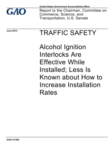
8 Operating the Fire PitThe following sections explain operation of:A. Remote control B. Smartphone controlLED forflash countA. HPC Remote Control – After turning ON the gas to fire pit, operateas follows:High1. Normal Remote Operation – Figure 8.1a. Power ON/OFF – 2 Flashb. High – 4 Flashc. Low – 3 Flashd. Poor Communication – 10 Flash (Move closer or change positions.)e. Remote Response Time – When not in use for more than 30 seconds, theremote will go into a sleep mode to save battery life. If remote is in sleep modeit may take a few extra seconds for a command to be executed.Power On / OffFigure 8.12. Remote sync – The remote should arrive already synced to the fire pit. Figure 8.2a. If you need to sync the remote to a fire pit:1. Ensure power is OFF to fire pit.2. Depress the LOW and OFF button simultaneously and hold until theremote flashes rapidly (8 to 10 seconds)3. Release the LOW and OFF buttons4. Apply power to the fire pit within 10 seconds – Fire pit will accept a newremote for the first 60 minutes it is on.5. Allow the remote to finish flashing which could take up to 30 seconds6. Your remote should operate the fire pitNOTE: If steps 5 or 6 fail, please repeat Steps 1 through 4. Also confirm antennaplacement, see Section 6 – Installing the Fire Pit.IMPORTANTThe maximum of devices that can be paired to a HI/LOfire pit at one time is 9 devices. This includes the remotecontrol that comes with your HI/LO fires pit and yoursmartphone or tablet. When pairing the tenth device thefirst four paired devices will be removed from memoryand the sequence starts again.22Figure 8.2
8 Operating the Fire Pit3. Remote Range – The remote should reliably operatewithin a 25-foot distance from your fire pit. Greaterdistances may be possible depending on your particularapplication. Antenna extension cable is available whenneeded. See Fig
- HPC highly recommends using our HPC/Sebco 24 VAC 100W power supply series (311-PS1, 311-PS3, 311-PS5 Models) A Class II 24 VAC, 4-amp, 100 W transformer must be used to power the fire pit and be able to be switched on and off from a remote location to allow for easy access or emergency. - 24 VAC wire sizing: Wire lengths 75 ft or less: 14 gauge