Transcription
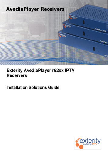
Exterity AvediaPlayer r92xx IPTVReceiversInstallation Solutions Guide
AvediaPlayer r92xx Installation Solutions GuideNoticesDisclaimer Exterity Limited 2003-2011The information contained in this document issubject to change without notice.This document contains information that isprotected by copyright. Reproduction,adaptation, or translation without priorpermission is prohibited, except as under thecopyright laws.Document Reference1300-0032-0002EditionEXTERITY LIMITED MAKES NO WARRANTYOF ANY KIND WITH REGARD TO THISMATERIAL, INCLUDING, BUT NOT LIMITEDTO, THE IMPLIED WARRANTIES OFMERCHANTABILITY AND FITNESS FOR APARTICULAR PURPOSE. Exterity Limitedshall not be liable for errors contained herein orfor incidental or consequential damages inconnection with the furnishing, performance, oruse of this material.Issue 2 (June 2011)WarrantyPrinted in UKExterity LimitedRidge WayHillend Industrial ParkDalgety Bay,Fife,KY11 9JDScotland, UKhttp://www.exterity.comProducts Described By This Guide A copy of the specific warranty terms applicableto your Exterity products and replacement partscan be obtained from Exterity. To request moreinformation or parts, emailsupport@exterity.comSafety NoticesBefore installing and operating these products,please read the safety information in thismanual.Wall Integrated Bracket - Exterity avply-sbktUnder-desk/wall mounting bracket – Exterityavply-dbktDisplay rear mounting bracket (small) – Exterityavply-vsbktDisplay rear mounting bracket (large) – Exterityavply-vlbktSecure enclosure – Exterity avply-ebktTrademarksThe Exterity building IPTV logo, in-SocketTechnology, prodaptor, AvediaServer,AvediaPlayer, AvediaCentre and iSocket aretrademarks or registered trademarks of ExterityLimited. Microsoft , Windows , and Windows Media Player are U.S. registered trademarks ofMicrosoft Corporation.HDMI, the HDMI Logo and High-DefinitionMultimedia Interface are trademarks orregistered trademarks of HDMI Licensing LLC.All other trademarks are the property of theirrespective owners. All rights reserved.2Installer’s Guide
AvediaPlayer r92xx Installation Solutions GuideContentsContents. 31Introduction . 4Scope . 4Audience . 4Using the Installation Kits . 42The AvediaPlayer r92xx Receivers . 5General . 5HDMI . 5Power . 5Remote Control . 5Device Administration. 53Fitting a Kensington Lock. 64Fitting an Under-desk/Wall Mounting . 75Fitting TV Mounting Plates and Secure Enclosure . 9Attaching the Small TV Mounting plate . 9Attaching the Large TV Mounting Plate . 11Fitting the Enclosure . 13Attaching to a TV or Display . 156Installing the Wall Integrated Bracket. 16Wall Integrated Bracket Components . 16Installation Procedure. 171.Fitting the wall box . 172.Attaching the AvediaPlayer to the mounting bracket . 193.Connecting all cables to the AvediaPlayer r9200 . 204.Attach the AvediaPlayer r9200 to the Wall Integrated Bracket . 205.Fit Cable Clamps . 216.Fit the Wall Integrated Bracket Cover . 227.Final Step . 23APPENDIX ASupport and contact information . 24Installer’s Guide3
AvediaPlayer r92xx Installation Solutions Guide1 IntroductionScopeThis guide shows how to install an AvediaPlayer r92xx series IPTV receiver using theavailable mounting and installation kits.AudienceThis manual is intended for use by installation engineers qualified to carry out the fitting ofelectrical equipment in domestic and commercial premises.WARNING: Do not cut or drill into a wall without first satisfying yourself that it is safe to do so,having first eliminated the risk from all potential hazards such as hidden electrical cabling andother services.There are no instructions specifically for service personnel in this document. There are no userserviceable parts inside any Exterity product. To prevent electric shock or fire hazard, do notremove cover. Refer service to qualified service personnel.For all AvediaPlayer r92xx receiver safety and operating instructions, refer to the AvediaPlayerr92xx series Administrator’s Guide.Using the Installation KitsMounting bracket kits enable you to securely mount AvediaPlayer r92xx series receivers to atelevision and display, to a wall or under a surface such as a desk or shelf. An enclosureprovides a more secure housing for the receiver and cabling.The Wall Integrated Bracket enables installation in a wall cavity.Tamper-proof fixings can be used if you want to maximise the security of the installations. Youcan also use a Kensington Lock.Methods of installation include: Kensington Lock Small and Large TV/Display mounting plates Secure Enclosure for mounting plates Wall Integrated BracketNote: Only the AvediaPlayer r9200 receiver can be installed in the Wall Integrated Bracket.4Installer’s Guide
AvediaPlayer r92xx Installation Solutions Guide2 The AvediaPlayer r92xx ReceiversGeneralThe AvediaPlayer r92xx receiver are network devices which displays an IP network deliveredMPEG-2 transport stream (TS) on a television or display.The AvediaPlayer r92xx receivers provide the following AV outputs: Video: HDMI v1.3a* 480p, 576i, 576p, 720p, 1080i & 1080p @ 50Hz, 59.94Hz or60Hz Audio: HDMI v1.3a* (8 channel PCM or Bitstream), TOS (2 channel PCM orBitstream)* HDMI interface supports all features of v1.3a except deep color, enhanced colorimetry (xvYCC, gamut metadata),and DST/DSD audio featuresThe AvediaPlayer r9210 receiver provides additional support for analogue video and audiooutputs. Rear panel connections provide support for HD component, SD composite, SD SVideo, SD RGBS and analogue stereo outputs.The AvediaPlayer 9220 receiver has an internal Ethernet switch, allowing three additionalnetwork devices to be connected to the network through the receiver. It must be connected tothe network switch using the port marked Ethernet 1 (POE). The ports marked Ethernet 2, 3,and 4 can be used for other network devices, for example, a computer or IP phone.HDMIUse a standard HDMI cable to connect the AvediaPlayer to an HD television/display.PowerWhen installed in the Secure Wall installation, the AvediaPlayer r9200 receiver must bepowered through the network interface by Power over Ethernet (PoE) using any LAN Switch orMid-span device meeting 802.3af PoE specifications.Remote ControlThe AvediaPlayer r9200 front panel IR window is obscured when it is installed in the SecureWall Installation. A tethered Remote Control handset or an IR extender with an IR RemoteControl handset allow the user to carry out common functions such as selecting channels andcontrolling volume.Device AdministrationRefer to the AvediaPlayer r92xx Administrator’s Guide for operating information using theabove mechanisms.Installer’s Guide5
AvediaPlayer r92xx Installation Solutions Guide3 Fitting a Kensington LockFitting a Kensington type lock to the AvediaPlayer receiver offers a method of securing thedevice whilst allowing easy access to cables and re-positioning if required.The following are required: Kensington lock Secure anchor pointTo fit a Kensington Lock:1. Locate the Kensington lock slot at the right rear of the AvediaPlayer receiver as shown inFigure 1.2. Secure the non-lock end of the cable.3. Insert the lock into the AvediaPlayer slot and secure.Figure 1 Fitting a Kensington Lock6Installer’s Guide
AvediaPlayer r92xx Installation Solutions Guide4 Fitting an Under-desk/Wall MountingThe under-desk/wall mounting bracket allows you to locate any AvediaPlayer r92xx seriesreceiver to a surface such as a wall, or under a shelf or desk. Suitable positioning can allowcabling to be hidden whilst maintaining access to the front panel IR receiver window for remotecontrol purposes.The following are required: AvediaPlayer Under-surface/Wall mounting bracket – Exterity avply-dbkt 2 M2.5 x 4mm Pozidriv screws – supplied 2 suitable mounting screws – not supplied – as required for mounting surface materialFigure 2 Under-surface/Wall Mounting BracketTo fit the receiver to a surface:1. Locate and prize-off the 4 removable feet from the underside of the AvediaPlayerreceiver.Figure 3 Feet and Threaded MountingsInstaller’s Guide7
AvediaPlayer r92xx Installation Solutions Guide2. Align the AvediaPlayer receiver as shown in Figure 4 and attach to the bracket using the 2supplied M2.5x4mm Pozidriv screws.Figure 4 Attaching to the Under Surface Bracket3. Use suitable fasteners to attach the completed assembly to a wall, or to the underside of adesk or counter surface as shown in Figure 5.Figure 5 Under Surface Installation8Installer’s Guide
AvediaPlayer r92xx Installation Solutions Guide5 Fitting TV Mounting Plates and SecureEnclosureThe two TV Mounting Plates allow you to attach any AvediaPlayer r92xx series receiver to avariety of sizes of TVs or displays. The Secure Enclosure provides a degree of protection forthe AvediaPlayer receiver and cabling. Security can be further enhanced with the use oftamper-proof screws.Attaching the Small TV Mounting plateThe Small TV Mounting Plate allows you to attach any AvediaPlayer r92xx series receiver to aFlat TV or Display with mounting bracket sizes up to VESA MIS-E. The holes for mounting theAvediaPlayer receiver are counter sunk, allowing the plate to fit flat to the TV casing. Thesupplied same-thickness shims can be used to ensure a proper fit of a mounting bracketfixture if the mounting plate is to be mounted between the TV chassis and the mountingbracket. Attach the AvediaPlayer receiver to the mounting plate before fixing to a TV.Additionally, a ventilated enclosure can be fitted and is described on page 13. If required, itcan be secured using tamper-proof fixings.For this type of mounting, a tethered remote control or an IR receiver extender is likely to berequired to enable remote control of the receiver.The following are required: AvediaPlayer Small TV mounting plate – Exterity avply-vsbkt Remote Control with IR Extension – avply-rck, or Tethered Remote Control – avply-rct,or Infrared Extender only – avply-ir38. 4 M2.5x4 Pozidriv cross CSK flat head – supplied Suitable mounting screws – not supplied – typically M4 x 10mm TV mounting holesup to 100mm mount spacing, M6 x 10 mm up to 200 mm mount spacing.Figure 6 Small TV Mounting Plate DimensionsTo fit the receiver to a TV using the Small TV Mounting Plate:1. Locate and prize-off the 4 removable feet from the underside of the AvediaPlayerreceiver.Installer’s Guide9
AvediaPlayer r92xx Installation Solutions GuideFigure 7 Feet and Threaded Mountings2. Align the AvediaPlayer receiver as shown in Figure 8 and attach to the bracketusing 4 supplied M2.5 x4 Pozidriv cross CSK flat head screws.Figure 8 Attaching to the Small TV Mounting Plate3. The assembly is now ready to be attached to a TV. Refer to Attaching to a TV or Displayon page 15 for more information.10Installer’s Guide
AvediaPlayer r92xx Installation Solutions GuideAttaching the Large TV Mounting PlateThe Large TV Mounting Plate allows you to attach any AvediaPlayer r92xx series receiver to aFlat TV or Display with mounting bracket sizes up to VESA MIS-F. The holes for mounting theAvediaPlayer receiver are counter sunk, allowing the plate to fit flat to the TV casing. Samethickness shims can be used to ensure a proper fit if the mounting plate is to be mountedbetween the TV chassis and a mounting bracket. The AvediaPlayer receiver must be attachedto the mounting plate before the plate is attached to a TV.Additionally, a ventilated enclosure can be fitted and is described on page 13. If required, itcan be secured using tamper-proof fixings.For this type of mounting, a tethered remote control or an IR receiver extender is likely to berequired to enable remote control of the receiver.The following are required: AvediaPlayer Large TV mounting plate – Exterity avply-vlbkt 4 M2.5x4 Pozidriv cross CSK flat head – supplied Remote Control with IR Extension – avply-rck, or Tethered Remote Control – avply-rct,or Infrared Extender only – avply-ir38. Suitable mounting screws – not supplied – typically M4 x 10mm TV mounting holesup to 100mm mount spacing, M6 x 10mm up to 200mm, and M8 x 15mm for over200mm mount spacing.Figure 9 Large TV Mounting Plate DimensionsTo fit the receiver to a TV using the Large TV Mounting Plate:4. Locate and prize-off the 4 removable feet from the underside of the AvediaPlayer receiver.Figure 10 Feet and Threaded MountingsInstaller’s Guide11
AvediaPlayer r92xx Installation Solutions Guide5. Align the AvediaPlayer receiver as shown in Figure 8 and attach to the bracket using 4supplied M2.5x4 Pozidriv cross CSK flat head screws.Figure 11 Attached to the Large TV Mounting Plate6. The assembly is now ready to be attached to a TV. Refer to Attaching to a TV or Displayon page 15 for more information.12Installer’s Guide
AvediaPlayer r92xx Installation Solutions GuideFitting the EnclosureBoth Small and Large TV Mounting Plates allow fitment of the enclosure. The enclosureprovides a degree of protection for the AvediaPlayer receiver and cabling. Security can befurther enhanced with the use of tamper-proof screws.You can fit the enclosure before or after attaching the mounting plate to a TV.The following parts are required: AvediaPlayer Large or Small TV mounting plate – Exterity avply-vlbkt or avply-vsbkt AvediaPlayer Enclosure – part of Exterity avply-ebkt Remote Control with IR Extension – avply-rck, or Tethered Remote Control – avply-rct,or Infrared Extender only – avply-ir38. 2 M3x6mm pan head Pozidriv (or secure fixings)To fit the enclosure:Before fitting the enclosure ensure the AvediaPlayer receiver is securely attached to the Largeor Small TV mounting plate and all cables to the AvediaPlayer receiver are properly connectedand secured as shown:7. Route the cabling as required for the completed installation. Position the enclosure overthe TV mounting plate to align the 4 slotted holes in the enclosure over the 4 locating pegson the TV mounting plate as shown:8. Lower the enclosure and slide it to engage the locating pegs in the smaller ends of theslotted holes as shown:Installer’s Guide13
AvediaPlayer r92xx Installation Solutions Guide9. Fit the 2 M3x6mm pan head screws into the retaining lugs as shown, using securefasteners if required.10. The enclosure fitting is now complete.Sufficient space is available within the enclosure to allow any spare cable length to be coiledand tied.14Installer’s Guide
AvediaPlayer r92xx Installation Solutions GuideAttaching to a TV or DisplayThe TV Mounting Plates meet a wide variety of installations, allowing you to fix theAvediaPlayer receiver to the TV or display whilst enabling the use of the TV stand or widelyavailable mounting brackets.If you are using a wall mounting bracket, locate the AvediaPlayer TV mounting plate betweenthe bracket and the TV chassis. Position the supplied shims between the remaining bracketmount points and the TV chassis to ensure a flat fixing surface. Use the fixing screws suppliedwith the mounting bracket.A suggested fitting location for the Small TV Mounting Plate is shown in Figure 12.Figure 12 Mounting Plate Positioned for Wall BracketInstaller’s Guide15
AvediaPlayer r92xx Installation Solutions Guide6 Installing the Wall Integrated BracketThe AvediaPlayer r9200 receiver should be located close to the connected TV or displaydevice. A tethered Remote Control handset or an Infra Red extension is required as thisinstallation causes the device IR window to be obscured.Whilst taking into account the requirements of power for the TV/Display and access to the LANcabling (and power if not using PoE) for the AvediaPlayer receiver, consideration should begiven to the following: HDMI and TV Serial Control (if fitted) cable lengths - proximity of the TV/Display andSecure Wall Fitting placement Position of the Secure Wall Fitting if the tethered Remote Control handset is to beused Line-of-sight access if the IR remote extender is to be usedWall Integrated Bracket ComponentsThe following items are supplied: Wall Integrated Bracket – Exterity avply-sbkt, containing:o Back box assy – 1o Wall clamp bracket – 3o Mounting bracket – 1o Front Cover – 1o M3 x 6 combination Pozidriv screw – 2o M4 x 16 Pozidriv screw – 3o M2.5 x 4 Pozidriv countersunk screw – 2o Nut M3 – 4o Locking washer M3 – 4o P-clip 3.2mm – 1o P-clip 7.2mm – 1Figure 13 Secure Wall Fitting Major Components16Installer’s Guide
AvediaPlayer r92xx Installation Solutions GuideAdditional items required (not supplied with kit): AvediaPlayer r9200 IPTV Receiver – avply-r9200 Remote Control with IR Extension – avply-rck, or Tethered Remote Control – avply-rct, or Infrared Extender only – avply-ir38 HDMI connection cable of suitable lengthInstallation ProcedureUse the following procedure and supplied fixings to ensure a secure housing for the receiverand cabling.1. Fitting the wall boxThe Wall Integrated Bracket is a dry lining wall box suitable for common plasterboardthicknesses. It requires an opening of 162mm wide x 160mm high and is clamped to the wallusing 3 locating plates.Warning: DO NOT proceed beyond this point without first ensuring that it is safe to do so.To fit the wall box:1. Measure and cut an opening of 162mm wide x 160mm high at the required location.2. Locate and feed the LAN cable through a suitable wall box hole. Re-position therubber grommet if required.3. Set the wall box into the wall ensuring the stamped word “TOP” is at the top, asshown.Installer’s Guide17
AvediaPlayer r92xx Installation Solutions Guide4. Slide the 3 locating plates into place and tighten the 3 M3 x 16 Pozidriv screws untilthe wall box is firmly held.18Installer’s Guide
AvediaPlayer r92xx Installation Solutions Guide2. Attaching the AvediaPlayer to the mounting bracketThe AvediaPlayer r9200 is attached to the mounting bracket using the threaded mountings onthe rear underside of the device.To fit the receiver mounting bracket:1. Locate and prize-off the 2 removable feet from the rear-underside of theAvediaPlayer receiver.ThreadedMountingsRemovableFeet2. Attach the mounting bar to the receiver using the supplied countersunk M2.5 x 4Pozidriv screws.Installer’s Guide19
AvediaPlayer r92xx Installation Solutions Guide3. Connecting all cables to the AvediaPlayer r9200Connect the LAN, HDMI and remote control cables to the AvediaPlayer r9200.To connect the cables:1. Connect the HDMI Cable from the TV/Display.2. Connect either the tethered Remote Control handset cable, or the IR extendercable.3. Connect the AvediaPlayer receiver to the network cable using the ETHERNET port.4. Attach the AvediaPlayer r9200 to the Wall Integrated BracketTo fit the AvediaPlayer r9200 to the wall box:1. Position the AvediaPlayer and bracket assembly over the mounting screws.20Installer’s Guide
AvediaPlayer r92xx Installation Solutions Guide2. Whilst holding the assembly in place, fix the bracket to the wall box using two M3nuts and locking washers.5. Fit Cable ClampsThe cable clamps ensure that the cables cannot be pulled from their respective connectors.To fit the cable clamps:1. Fit the larger P-clip (7.2mm) over the HDMI cable and use an M3 nut and lockingwasher to fix it to the adjacent mounting screw.2. Fit the smaller P-clip (3.2mm) over the Remote Control cable and use an M3 nutand locking washer to fix it to the adjacent mounting screw.Installer’s Guide21
AvediaPlayer r92xx Installation Solutions Guide6. Fit the Wall Integrated Bracket CoverThe cover conceals the AvediaPlayer receiver and cables. You can further improve security byusing tamper-proof screws to attach it.To fit the cover:Position the cover so that the locating lugs fit over the slots on the upper edge ofthe wall box, and the mounting pegs on the lower edge.1. Maintain pressure on the cover and slide it downwards (2-3mm) to engage the topand bottom mounting lugs.2. Secure the cover using the two supplied M3 x 6 combination Pozidriv screws. Forimproved security, using tamper-proof fixings (not supplied).22Installer’s Guide
AvediaPlayer r92xx Installation Solutions Guide7. Final StepRefer to the AvediaPlayer r92xx series Administrator’s Guide for configuration and operatinginformation.When connected to a TV/Display, you can use the engineering screen to display informationabout the device including its name, IP address and firmware version. This may help youidentify individual devices.To display the engineering screen, press MODE and then PLAY on the remote control handset.To remove the engineering screen, press PLAY to return to the Mode menu, or press MODE tohide the menu completely.Installer’s Guide23
AvediaPlayer r92xx Installation Solutions GuideAPPENDIX A Support and contact informationTechnical Support for Exterity products is provided by authorised Systems Integrators andResellers. Please contact your Systems Integrator or Reseller with any Support issues.24Installer’s Guide
AvediaPlayer r92xx Installation Solutions Guide 4 Installer's Guide 1 Introduction Scope This guide shows how to install an AvediaPlayer r92xx series IPTV receiver using the available mounting and installation kits. Audience This manual is intended for use by installation engineers qualified to carry out the fitting of