Transcription
NXP SemiconductorsData Sheet: Technical DataDocument Number: SCMIMX6SXIECRev. 0, 02/2017SCM-i.MX 6SX Data Sheet for IndustrialProducts1. IntroductionNXP Single Chip System Modules (SCMs) are a suiteof highly integrated products in an ultra-small formfactor. The member of this portfolio, the NXP SCMi.MX 6SoloX, drastically reduces time to market byproviding a solution that minimizes design time. We’veintegrated and validated the i.MX 6SoloX applicationsprocessor with the power management system andLPDDR2 memory into a 13x13mm package. It is asmall yet powerful solution intended for use in a widevariety of industrial applications.The SCM-i.MX 6SoloX speeds and eases developmenttime by addressing technology challenges such asdesign of DDR and power management. Our singlechip module consists of the i.MX 6SoloX applicationsprocessor, MMPF0100 (PMIC) for power management,along with a mix of discrete components, and isenabled for LPDDR2 memory through a PoP packageassembly.NXP reserves the right to change the production detailspecifications as may be required to permit improvementsin the design of its products.Downloaded from Arrow.com.Contents1.2.3.4.5.6.7.8.Introduction . 11.1.Ordering information . 21.2.Features . 21.3.References. 3Architectural overview . 32.1.Block diagram . 3Modules list. 43.1.Special signal considerations . 133.2.PMIC electrical deratings. 14Electrical characteristics. 144.1.Chip-level conditions . 14Power supplies requirements and restrictions . 165.1.Power-up sequences . 165.2.Power-down sequences . 165.3.Power supplies usage . 165.4.Boot configuration . 16Boot mode configuration. 186.1.Boot mode configuration pins . 186.2.Boot devices interfaces allocation . 18Package information . 187.1.Signal list . 187.2.Ball map . 237.3.Package drawings. 25Revision history . 26
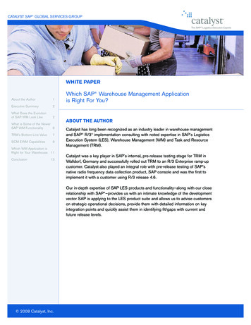
Introduction1.1. Ordering informationFigure 1. Part number nomenclatureThe table below shows examples of orderable part numbers.Table 1. Orderable part numbersPart NumberCortex A9 Speed1Junction Temperature RangePackage TypeMSCMMX6XYCM08AA800 MHzIndustrial: -40 to 105 C265 pin BGA1. If a 24 MHz input clock is used (required for USB), the maximum Cortex-A9 speed for 800 MHz speed grade is limited to792 MHz.1.2. FeaturesThe SCM-i.MX 6SoloX integrates the i.MX6SoloX processor with the MMPF0100 PMIC inside a13x13mm BGA package that supports a variety of LPDDR2 memory configurations through a 168ballPoP interface. This part is packaged in a 265 pin BGA which uses a diagonal ball array and a 0.75mmpitch to allow for all pins to be brought out on a 4-layer PCB.1.2.1. i.MX 6SoloX featuresThe i.MX 6SoloX processor features NXP's advanced implementation of the single ARM Cortex -A9core in addition to the ARM Cortex-M4 core. This type of heterogeneous multicore architectureprovides greater levels of system integration, smart low-power system awareness, and fast real-timeSCM-i.MX 6SX Data Sheet for Industrial Products, Data Sheet: Technical Data, Rev. 0, 02/20172Downloaded from Arrow.com.NXP Semiconductors
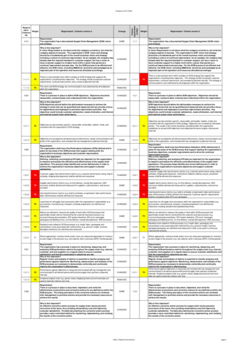
Architectural overviewresponsiveness. The i.MX 6SoloX includes a GPU processor capable of supporting 2D and 3Doperations, a wide range of display and connectivity options, and integrated power management.For a full list of module features see Table 3.1.2.2. MMPF0100 Features in this Package Three buck converters.Boost regulator to 5.0 V output for USB OTG support.Three general purpose linear regulatorsProgrammable output voltage, sequence, and timingOTP (One Time Programmable) memory for device configurationCoin cell charger and RTC supplyPower control logic with processor interface and event detectionI2C controlIndividually programmable ON, OFF, and Standby modes1.3. ReferencesThis document is intended to be a companion to the data sheets of the following integrated parts: NXP i.MX SoloX Data Sheet for Industrial Products (document IMX6SXIEC) NXP MMPF0100 (document MMPF0100Z)2. Architectural overviewThe following subsections provide an architectural overview of the SCM-i.MX 6SoloX system.2.1. Block diagramThe following figure shows the main functional relationship between the i.MX6SX, PMIC, Memory andPCB in the SCM-i.MX 6SoloX. It purposely does not show all of the functional modules in the part –that is found in Section 3, “Modules list”.SCM-i.MX 6SX Data Sheet for Industrial Products, Data Sheet: Technical Data, Rev. 0, 02/2017NXP SemiconductorsDownloaded from Arrow.com.3
Modules listFigure 2. SCM-i.MX 6SX block diagram3. Modules listTable 2. SCM modules overviewBlock Namei.MX 6SoloXMMPF0100LPDDR2 PoP InterfaceDescription/NotesFreescale i.MX 6SoloX Applications Processor. Defeatured from thestandard discrete part. See Table 3 for details on feature availability and/orderatings.Power management IC requires only a single supply and can provide powerand voltage references to entire SCM. See Section 4, “Electricalcharacteristics” for electrical details.Interface to support LPDDR2 in PoP configuration using a 12mm x 12mmFBGA168 footprint.SCM-i.MX 6SX Data Sheet for Industrial Products, Data Sheet: Technical Data, Rev. 0, 02/20174Downloaded from Arrow.com.NXP Semiconductors
Modules listThe SCM-i.MX 6SoloX processors contain a variety of digital and analog modules. This table describesthese modules in alphabetical order:Table 3. SCM-i.MX 6SoloX modules listBlockBlock NameSubsystemBrief DescriptionAvailability—The ADC is a 12-bit general purpose analog todigital converter.Only 3channels ofADC1Full FeatureMnemonicADC1Analog to DigitalConverterARMARM PlatformARMASRCAsynchronousSampleRate ConverterMultimediaPeripheralsAUDMUXDigital Audio MuxMultimediaPeripheralsBCHBinary-BCH ECCProcessorSystem ControlPeripheralsCAAMCryptographicaccelerator andassurancemoduleSecurityCCMGPCSRCClock ControlModule,General PowerController,Clocks, Resets,and Power ControlThe ARM Core Platform includes 1xCortex-A9and 1xCortex-M4 cores. It also includesassociated sub-blocks, such as the Level 2Cache Controller, SCU (Snoop Control Unit),GIC (General Interrupt Controller), privatetimers, watchdog, and CoreSight debugmodules.The Asynchronous Sample Rate Converter(ASRC) converts the sampling rate of a signalassociated to an input clock into a signalassociated to a different output clock. TheASRC supports concurrent sample rateconversion of up to 10 channels of about 120dB THD N. The sample rate conversion ofeach channel is associated to a pair ofincoming and outgoing sampling rates. TheASRC supports up to three sampling rate pairs.The AUDMUX is a programmable interconnectfor voice, audio, and synchronous data routingbetween host serial interfaces (for example,SSI1, SSI2, and SSI3) and peripheral serialinterfaces (audio and voice codecs). TheAUDMUX has seven ports with identicalfunctionality and programming models. Adesired connectivity is achieved by configuringtwo or more AUDMUX ports.The BCH module provides up to 62-bit ECCencryption/decryption for NAND Flash controller(GPMI)CAAM is a cryptographic accelerator andassurance module. CAAM implements severalencryption and hashing functions, a run-timeintegrity checker, and a Pseudo RandomNumber Generator (PRNG). The pseudorandom number generator is certified byCryptographic Algorithm Validation Program(CAVP) of National Institute of Standards andTechnology (NIST). Its DRBG validationnumber is 94 and its SHS validation number is1455. CAAM also implements a SecureMemory mechanism. In i.MX 6SoloXprocessors, the security memory provided is 32KB.These modules are responsible for clock andreset distribution in the system, and also for thesystem power management.Full FeatureFull FeatureFull FeatureFull FeatureFull FeatureSCM-i.MX 6SX Data Sheet for Industrial Products, Data Sheet: Technical Data, Rev. 0, 02/2017NXP SemiconductorsDownloaded from Arrow.com.5
Modules listTable 3. SCM-i.MX 6SoloX modules listBlockBlock NameSubsystemBrief DescriptionAvailabilityMultimediaPeripheralsThe CSI IP provides parallel CSI standardcamera interface port. The CSI parallel dataports are up to 24 bits. It is designed to support24-bit RGB888/YUV444, CCIR656 videointerface, 8-bit YCbCr, YUV or RGB, and 8bit/10-bit/26-bit Bayer data input.The Central Security Unit (CSU) is responsiblefor setting comprehensive security policy withinthe i.MX 6SoloX platform.Cross Trigger Interfaces allows cross-triggeringbased on inputs from masters attached to CTIs.The CTI module is internal to the Cortex-A9Core Platform.The DAP provides real-time access for thedebugger without halting the core to: Systemmemory and peripheral registers All debugconfiguration registers The DAP also providesdebugger access to JTAG scan chains. TheDAP module is internal to the Cortex-A9 CorePlatform.DBGMON is a real-time debug monitor torecord last AXI transaction before system reset.Full-duplex enhanced Synchronous SerialInterface, with data rate up to 52 Mbit/s. It isconfigurable to support Master/Slave modes,four chip selects to support multiple peripherals.Full FeatureThe EIM NOR-FLASH / PSRAM provides:Support 16-bit (in muxed IO mode only)PSRAMmemories (sync and async operating modes),at slow frequency Support 16-bit (in muxed IOmode only) NOR-Flash memories, at slowfrequency Multiple chip selectsThe Ethernet Media Access Controller (MAC) isdesigned to support 10/100/1000 MbpsEthernet/IEEE 802.3 networks. An externaltransceiver interface and transceiver functionare required to complete the interface to themedia. The module has dedicated hardware tosupport the IEEE 1588 standard. See theENET chapter of the i.MX 6SoloX ApplicationsProcessor Reference Manual (documentIMX6SXRM) for details.Each EPIT is a 32-bit “set and forget” timer thatstarts counting after the EPIT is enabled bysoftware. It is capable of providing preciseinterrupts at regular intervals with minimalprocessor intervention. It has a 12-bit prescalerfor division of input clock frequency to get therequired time setting for the interrupts to occur,and counter value can be programmed on thefly.The Enhanced Serial Audio Interface (ESAI)Full FeatureMnemonicSystem ResetControllerParallel CSICSICSUCentral SecurityUnitSecurityCTICross TriggerInterfacesDebug/TraceDAPDebug AccessPortSystem ControlPeripheralsDBGMONDebug gurable Interrupt TimerTimer PeripheralsESAIEnhanced SerialConnectivityFull FeatureFull FeatureFull FeatureFull FeatureFull FeatureOnly RGMII1availableNot availableFull FeatureSCM-i.MX 6SX Data Sheet for Industrial Products, Data Sheet: Technical Data, Rev. 0, 02/20176Downloaded from Arrow.com.NXP Semiconductors
Modules listTable 3. SCM-i.MX 6SoloX modules listBlockBlock NameSubsystemBrief N2Flexible ControllerAreaNetworkConnectivityPeripheralsFuse BoxElectrical FuseArraySecurityGC400TGraphics EngineMultimediaPeripheralsGICGlobal InterruptControllerARM/ControlGISGeneral InterruptServicemoduleGeneral PurposeI/OModulesCamera, Display,&GraphicsSystem ControlPeripheralsprovides a full-duplex serial port for serialcommunication with a variety of serial devices,including industry-standard codecs, SPDIFtransceivers, and other processors. The ESAIconsists of independent transmitter andreceiver sections, each section with its ownclock generator. All serial transfers aresynchronized to a clock. Additionalsynchronization signals are used to delineatethe word frames. The normal mode of operationis used to transfer data at a periodic rate, oneword per period. The network mode is alsointended for periodic transfers; however, itsupports up to 32 words (time slots) per period.This mode can be used to build time divisionmultiplexed (TDM) networks. In contrast, theon-demand mode is intended for non-periodictransfers of data and to transfer data serially athigh speed when the data becomes available.The ESAI has 12 pins for data and clockingconnection to external devices.The CAN protocol was primarily, but not only,designed to be used as a vehicle serial databus, meeting the specific requirements of thisfield: real-time processing, reliable operation inthe Electromagnetic interference (EMI)environment of a vehicle, cost-effectivenessand required bandwidth. The FlexCAN moduleis a full implementation of the CAN protocolspecification, Version 2.0 B, which supportsboth standard and extended message frames.Electrical Fuse Array. Enables setup of bootmodes, security levels, security keys, and manyother system parameters. The fuses areaccessible through OCOTP CTRL interface.The GC400T is a graphics engine with separate2D and 3D pipelines to provide both 2D and 3Dacceleration. It supports DirectFB and GALAPIs. It supports OpenGL ES1.1/2.0 andOpenVG 1.1 APIs.The Global Interrupt Controller (GIC) collectsinterrupt requests from all i.MX 6SoloX sourcesand routes them to the ARM MPCore(s). Eachinterrupt can be configured as a normal or asecure interrupt. Software Force Registers andsoftware Priority Masking are also supported.This IP is part of the ARM Core complex.GIS can be used to automate the flow of datafrom the camera to the IO5GPIO6GPIO7Full FeatureFull FeatureFull FeatureFull FeatureFull FeatureUsed for general purpose input/output toexternal ICs. Each GPIO module supports 32bits of I/O.ReducedGPIO’s.SCM-i.MX 6SX Data Sheet for Industrial Products, Data Sheet: Technical Data, Rev. 0, 02/2017NXP SemiconductorsDownloaded from Arrow.com.7
Modules listTable 3. SCM-i.MX 6SoloX modules listBlockBlock NameSubsystemBrief DescriptionAvailabilityGPMIGeneral PurposeMemory InterfaceConnectivityPeripheralsFull FeatureGPTGeneral PurposeTimerTimer PeripheralsI2C-1I2C-2I2C-3I2C-4IOMUXCI2C InterfaceConnectivityPeripheralsThe GPMI module supports up to 8x NANDdevices and 60-bit ECC encryption/decryptionfor NAND Flash Controller (GPMI2). GPMIsupports separate DMA channels for eachNAND device.Each GPT is a 32-bit “free-running” or “set andforget” mode timer with programmableprescaler and compare and capture register. Atimer counter value can be captured using anexternal event and can be configured to triggera capture event on either the leading or trailingedges of an input pulse. When the timer isconfigured to operate in “set and forget” mode,it is capable of providing precise interrupts atregular intervals with minimal processorintervention. The counter has output comparelogic to provide the status and interrupt atcomparison. This timer can be configured to runeither with an external clock or an internalclock.I2C provide serial interface for external devices.Data rates of up to 400 kbps are supported.IOMUX ControlSystem ControlPeripheralsKPPKey Pad PortConnectivityPeripheralsLCDIFLCD InterfaceMultimediaPeripheralsLVDS (LDB)LVDS Multi-Mode nectivityPeripheralsMUMessaging UnitInterprocessorMnemonicThis module enables flexible IO multiplexing.Each IO pad has default and several alternatefunctions. The alternate functions are softwareconfigurable.KPP Supports 8x8 external key pad matrix.KPP features are: Open drain design Glitch suppression circuit design Multiple keys detection Standby key press detectionThe LCDIF provides display data for externalLCD panels from simple text-only displays toWVGA, 16/18/24 bpp color TFT panels. TheLCDIF supports all of these different interfacesby providing fully programmable functionalityand sharing register space, FIFOs, and ALUresources at the same time. The LCDIFsupports RGB (DOTCLK) modes as well assystem mode including both VSYNC andWSYNC modes.LVDS Display Bridge is used to connect anexternal LVDS display interface. LDB supportsthe following signals: One clock pair Four data pairsThe MLB interface module provides a link to aMOST data network, using the standardizedMediaLB protocol (MOST25, MOST 50).DDR Controller supports 32-bit LP-DDR2-800The MU module supports interprocessorNot available.Full FeatureFull FeatureReduced KPPpins.Full FeatureFull FeatureFull FeaturePoP memoryon FullFeatureFull FeatureSCM-i.MX 6SX Data Sheet for Industrial Products, Data Sheet: Technical Data, Rev. 0, 02/20178Downloaded from Arrow.com.NXP Semiconductors
Modules listTable 3. SCM-i.MX 6SoloX modules listBlockBlock NameSubsystemBrief DescriptionComm. & Synch.communication between the Cortex-A9 andCortex-M4 cores.The On-Chip OTP controller (OCOTP CTRL)provides an interface for reading, programming,and/or overriding identification and controlinformation stored in on-chip fuse elements.The module supports electrically-programmable(eFUSE) polyfuses. The OCOTP CTRL alsoprovides a set of volatile software-accessiblesignals that can be used for software control ofhardware elements, not requiring non-volatility.The OCOTP CTRL provides the primary uservisible mechanism for interfacing with on-chipfuse elements. Among the uses for the fusesare unique chip identifiers, mask revisionnumbers, cryptographic keys, JTAG securemode, boot characteristics, and various controlsignals, requiring permanent non-volatility.The On-Chip Memory controller (OCRAM)module is designed as an interface betweensystem’s AXI bus and internal (on-chip) SRAMmemory module.Internal RAM, which is accessed throughOCRAM memory controller.Secure/nonsecure internal RAM, interfacedthrough the CAAM. OCRAM S can be used bysoftware for state retention of the CPU andother hardware blocks.Generates 32.768 KHz clock from externalcrystal.The PCIe IP provides PCI Express Gen 2.0functionality.Integrated power management unit. Used toprovide power to various SoC domains.The pulse-width modulator (PWM) has a 16-bitcounter and is optimized to generate soundfrom stored sample audio images and it canalso generate tones. It uses 16-bit resolutionand a 4x16 data FIFO to generate sound.AvailabilityMnemonicOCOTP CTRLOTP ControllerSecurityOCRAMOn-Chip MemoryControllerData PathOCRAM 128KBOCRAM S16KBInternal RAMInternal MemorySecure/nonsecureRAMSecured InternalMemoryOSC32KHzOSC32KHzClockingPCIePCI Express 2.0PMUPower-Mgmt.ConnectivityPeripheralsData se WidthModulationQSPIQuad ot ROMResource DomainControllerSemaphoreInternal n/PiXel ProcessingPipelineROM alsA high-performance pixel processor capable of1 pixel/clock performance for combinedoperations, such as color-space conversion,alpha blending, gamma-mapping, and rotation.The PXP is enhanced with features specificallyfor gray scale applications.The Quad Serial Peripheral Interface(QuadSPI) block acts as an interface to one ortwo external serial flash devices, each with upto four bidirectional data lines.Supports secure and regular boot modesRDC module supports domain-based accesscontrol to shared resources.Supports hardware-enforced semaphores.Full FeatureFull FeatureFull FeatureFull FeatureFull FeatureNot availableFull FeatureFull FeatureFull FeatureFull FeatureFull FeatureFull FeatureFull FeatureSCM-i.MX 6SX Data Sheet for Industrial Products, Data Sheet: Technical Data, Rev. 0, 02/2017NXP SemiconductorsDownloaded from Arrow.com.9
Modules listTable 3. SCM-i.MX 6SoloX modules listBlockBlock NameSubsystemBrief DescriptionAvailabilitySEMA42 is similar to SEMA4 with the followingkey differences: SEMA42 increases the number of accessdomains from 2 to 15 SEMA42 does not have interrupt toindicate semaphore release RDC programming model supports theoption to require hardware semaphore forperipherals shared between domains.Signaling between the SEMA42 and RDCbinds peripherals to semaphore gateswithin SEMA42.The SAI module provides a synchronous audiointerface (SAI) that supports full duplex serialinterfaces with frame synchronization, such asI2S, AC97, TDM, and codec/DSP interfaces.The SDMA is multi-channel flexible DMAengine. It helps in maximizing systemperformance by off-loading the various cores indynamic data routing. It has the followingfeatures: Powered by a 16-bit Instruction-Set microRISC engine Multi-channel DMAsupporting up to 32 time-divisionmultiplexed DMA channels. 48 events with total flexibility to trigger anycombination of channels. Memory accesses including linear, FIFO,and 2D addressing. Shared peripherals between ARM andSDMA Very fast Context-Switching with 2level priority based preemptive multitasking. DMA units with auto-flush and prefetchcapability Flexible address managementfor DMA transfers (increment, decrement,and no address changes on source anddestination address). DMA ports can handle unit-directional andbi-directional flows (copy mode). Up to 8-word buffer for configurable bursttransfers for EMIv2.5. Support of byte-swapping and CRCcalculations. Library of Scripts and API is availableThe SJC provides JTAG interface, whichcomplies with JTAG TAP standards, to internallogic. The i.MX 6SoloX processors use JTAGport for production, testing, and systemdebugging. In addition, the SJC provides BSR(Boundary Scan Register) standard support,which complies with IEEE1149.1 andIEEE1149.6 standards. The JTAG port must beaccessible during platform initial laboratorybring-up, for manufacturing tests andFull lation/SharingSAI1SAI2SDMASmart DirectMemoryAccessSJCSystem JTAGControllerSystem ControlPeripheralsSystem ControlPeripheralsFull FeatureFull FeatureFull FeatureSCM-i.MX 6SX Data Sheet for Industrial Products, Data Sheet: Technical Data, Rev. 0, 02/201710Downloaded from Arrow.com.NXP Semiconductors
Modules listTable 3. SCM-i.MX 6SoloX modules listBlockBlock NameSubsystemBrief DescriptionAvailabilitytroubleshooting, as well as for softwaredebugging by authorized entities. The i.MX6SoloX SJC incorporates three security modesfor protecting against unauthorized accesses.Modes are selected through eFUSEconfiguration.Secure Non-Volatile Storage, including SecureReal Time Clock, Security State Machine,Master Key Control, andViolation/Tamper Detection and reporting.A standard audio file transfer format, developedjointly by the Sony and Phillips corporations.Has transmitter and receiver functionality.Full FeatureMnemonicSNVSSecure NonVolatileStorageSecuritySPDIFSony PMONTemperatureMonitorSystem ControlPeripheralsTVDECODETV Decoder ressSpace RT InterfaceConnectivityPeripheralsuSDHC1SD/MMC andConnectivitySSI1SSI2SSI3The SSI is a full-duplex synchronous interface,which is used on the AP to provide connectivitywith off-chip audio peripherals. The SSIsupports a wide variety of protocols (SSInormal, SSI network, I2S, and AC-97), bitdepths (up to 24 bits per word), and clock /frame sync options. The SSI has two pairs of8x24 FIFOs and hardware support for anexternal DMA controller in order to minimize itsimpact on system performance. The secondpair of FIFOs provides hardware interleaving ofa second audio stream that reduces CPUoverhead in use cases where two time slots arebeing used simultaneously.The Temperature sensor IP is used fordetecting die temperature. The temperatureread out does not reflect case or ambienttemperature. It reflects the temperature inproximity of the sensor location on the die.Temperature distribution may not be uniformlydistributed, therefore the read out value maynot be the reflection of the temperature value ofthe entire die.The TVDEC decodes NTSC/PAL input fromVADC analog front end and provides YUV888data CSI.The TZASC (TZC-380 by ARM) providessecurity address region control functionsrequired for intended application. It is used onthe path to the DRAM controller.Each of the UARTv2 modules support thefollowing serial data transmit/receive protocolsand configurations: 7- or 8-bit data words, 1 or 2 stop bits,programmable parity (even, odd or none) Programmable baud rates up to 5 Mbps.32-byte FIFO on Tx and 32 half-word FIFOon Rx supporting auto-baud Option to operate as 8-pins full UART,DCE, or DTE UART1/6 support 8-pin,UART2/3/4/5 support 4-pini.MX 6SoloX specific SoC characteristics: AllFull FeatureFull FeatureFull FeatureNot availableFull FeatureReducedfunctionalityfor UART1and UART2.uSDHC1 is notSCM-i.MX 6SX Data Sheet for Industrial Products, Data Sheet: Technical Data, Rev. 0, 02/2017NXP SemiconductorsDownloaded from Arrow.com.11
Modules listTable 3. SCM-i.MX 6SoloX modules listBlockBlock NameSubsystemBrief ced MultiMediaCard / SecureDigital HostControllerPeripheralsavailable.USBUniversal SerialBus 2.0ConnectivityPeripheralsVADCVideo ADCConnectivityPeripheralsfour MMC/SD/SDIO controller IPs are identicaland are based on the uSDHC IP. They are: Fully compliant with MMCcommand/response sets and PhysicalLayer as defined in the Multimedia CardSystem Specification,v4.5/4.2/4.3/4.4/4.41/ including highcapacity (size 2 GB) cards HC MMC. Fully compliant with SDcommand/response sets and PhysicalLayer as defined in the SD Memory CardSpecifications, v3.0 including high-capacitySDHC cards up to 32 GB. Fully compliant with SDIOcommand/response sets andinterrupt/read-wait mode as defined in theSDIO Card Specification, Part E1, v3.0 All four ports support: 1-bit or 4-bit transfermode specifications for SD and SDIOcards up to UHS-I SDR104 mode (104MB/s max) 1-bit, 4-bit, or 8-bit transfermode specifications for MMC cards up to52 MHz in both SDR and DDR modes (104MB/s max) However, the SoC level integration and I/Omuxing logic restrict the functionality to thefollowing: Instances #1 and #2 areprimarily intended to serve as interfaces toon-board peripherals. These ports areequipped with “Card detection” and “WriteProtection” pads and do not supporthardware reset. Instance #3 is intended toserve as the primary external card slot. Instance #4 is intended to be the primaryboot device via eMMC or SD, or to be asecondary external card slot. Instances #3and #4 do not have “Card detection” and“Write Protection” pads and do supporthardware reset. All ports can work with 1.8V and 3.3 V cards. There are twocompletely independent I/O powerdomains for Ports #1 and #2 in four bitconfiguration (SD interface). Port #3 isplaced in his own independent powerdomain and port #4 shares power domainwith some other interfaces.USB contains: Two high-speed OTG 2.0 modules withintegrated HS USB PHYs One high-speed Host module connected toHSIC USB portVideo ADC digitizes an analog video signal,such as one from an inexpensive analogcamera. The video signal can be selected fromone of four inputs, VIN0-VIN3, through registercontrol.MnemonicFull FeatureNot availableSCM-i.MX 6SX Data Sheet for Industrial Products, Data Sheet: Technical Data, Rev. 0, 02/201712Downloaded from Arrow.com.NXP Semiconductors
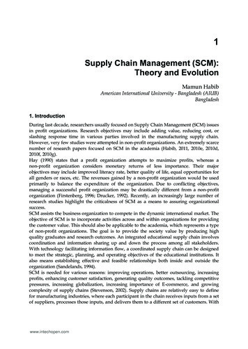
Modules listTable 3. SCM-i.MX 6SoloX modules listBlockBlock NameSubsystemBrief DescriptionAvailabilityWDOG1WDOG3Watch DogTimer PeripheralsReducedWDOG pins.WDOG2(TZ)Watch Dog(TrustZone)Timer PeripheralsXTALOSCCrystal OscillatorInterfaceClocks, Resets,and Power ControlThe Watch Dog Timer supports two comparisonpoints during each counting period. Each of thecomparison points is configurable to evoke aninterrupt to the ARM core, and a second pointevokes an external event on the WDOG line.The TrustZone Watchdog (TZ WDOG) timermodule protects against TrustZone starvationby providing a method of escaping normalmode and forcing a switch to the TZ mode. TZstarvation is a situation where the normal OSprevents switching to the TZ mode. Suchsituation is undesirable as it can compromisethe system’s security. Once the TZ WDOGmodule is activated, it must be serviced by TZsoftware on a periodic basis. If servicing doesnot take place, the timer times out. Upon atime-out, the TZ WDOG asserts a TZ mappedinterrupt that forces switching to the TZ mode. Ifit is still not served, the TZ WDOG asserts asecurity violation signal to the CSU. The TZWDOG module cannot be programmed ordeactivated by a normal mode software.The XTALOSC module connects to an externalcrystal to provide system clocks.MnemonicReducedWDOG2 pins.Full Feature3.1. Special signal considerationsThe figure below shows critical internal module connections.SCM-i.MX 6SX Data Sheet for Industrial Products, Data Sheet: Technical Data, Rev. 0, 02/2017NXP SemiconductorsDownloaded from Arrow.com.13
Electrical characteristicsFigure 3. SCM-i.MX6SX critical internal connections3.2. PMIC electrical deratingsThe MMPF0100 PMIC has been integrated into the
(CAVP) of National Institute of Standards and Technology (NIST) . Its DRBG validation number is 94 and its SHS validation number is 1455. CAAM also implements a Secure Memory mechanism. In i.MX 6SoloX processors, the security memory provided is 32 KB. Full Feature CCM GPC . SRC . Clock Control Module, General Power . Contro ller, Clocks, Resets,