Transcription
White Paperwww.rad.comCorporate HeadquartersRAD Data Communications Ltd.24 Raoul Wallenberg StreetTel Aviv 69719, IsraelTel: 972-3-6458181Fax: 972-3-6498250email: market@rad.comwww.rad.comInnovative Access SolutionsU.S. HeadquartersRAD Data Communications Inc.900 Corporate DriveMahwah, NJ 07430 USATel: (201) 529-1100,Toll Free: 1-800-444-7234Fax: (201) 529-5777email: market@radusa.comwww.radusa.comThe RAD name and logo are registered trademarks of RAD Data Communications Ltd.TDMoIP is a registered trademark of RAD Data Communications Ltd. 2006 RAD Data Communications. All rights reserved. Subject to change without notice.Catalog no. 802354 Version 3/2006Ethernet OAMBy Yaakov (Jonathan) Stein, Chief ScientistRAD Data CommunicationsInnovative Access Solutions
AbstractUntil recently Ethernet lacked OAM functionality like that found in inSONET/SDH or ATM, and therefore was not characterized as “carrier class.”Now it has acquired two types of OAM, one developed by the ITU and IEEE802.1, and another by the EFM task force. The former is a full-featuredOAM mechanism that can run end-to-end and includes all traditional OAMelements such as AIS, RDI and performance measurement. The latter islimited to continuity monitoring of a single link and is targeted at accessapplications. As the former protects the Ethernet service layer and thelatter the Ethernet physical layer, the two can be complementary.However, it is not clear why there is a need for two different standards.
White Paper: Ethernet OAMContentsIntroduction . 2OAM for Ethernet . 3OAM Functions. 4EFM (802.3ah) Link-layer OAM. 8Y.1731/802.1ag Service OAM. 11Summary . 16 2006 RAD Data Communications Ltd.1
White Paper: Ethernet OAMIntroductionOAM (Operation, Administration, and Maintenance) describes the monitoring of networkoperation by network operators. OAM is a set of functions used by the user that enablesdetection of network faults and measurement of network performance, as well asdistribution of fault-related information. OAM may trigger control plane or managementplane mechanisms, e.g. by activating rerouting or by raising alarms, but such functions arenot part of the OAM itself. OAM functionality ensures that network operators comply withQoS guarantees, detect anomalies before they escalate, and isolate and bypass networkdefects. As a result, the operators can offer binding service-level agreements. Theoperation of networks without OAM demands many more resources for continuous manualintervention to detect failures, expensive truck rolls to localize faults, and humanperformance measurement. These networks have lower availability and longer down times,and are more expensive to maintain.OAM is generally utilized for detecting and localizing network faults, examining andreporting network status, monitoring network performance, and provisioning andconfiguring user parameters. Traditional TDM systems provide OAM fields in their overhead,while modern packet-switched network OAM protocols may exploit packet overhead topiggyback OAM information onto user traffic, but more frequently introduce specialpurpose OAM packets alongside user packets.Each layer of a layered network needs its own OAM. For example, a VoIP application runover an IP network and layered on an ATM network supported by a SONET infrastructureneeds four types of OAMs: Application layer OAM for the VoIP based on RTP mechanisms IP layer OAM (usually limited to troubleshooting by ping and traceroute) ATM layer OAM SONET OAM (at the bottom of the stack).By keeping these OAM mechanisms distinct, end-users, service providers and networkoperators can each monitor the status of functions for which they are responsible, andmake corrections without involving others. While defects on one network layer will usuallyimpact higher layers (such as server layer defects which cause loss of client layerinformation), faults detected on one layer do not necessarily imply correlated faults onlower layers.2 2006 RAD Data Communications Ltd.
White Paper: Ethernet OAMOAM mechanisms were first devised for PDH networks, and included AIS and RDIcomponents (see below). PDH OAMs became more sophisticated, and with the advent ofSONET/SDH OAM became a crucial network component. TDM OAMs supported the famous“five nines” availability and reliability, and 50 millisecond recovery times from failures. ATMincluded fault detection and performance measurement OAMs from its initial design stages,and MPLS has several flavors of OAM developed by the IETF and by the ITU. Ethernet is themost recent communications protocol to adopt OAM capabilities.OAM for EthernetEthernet originated as a Local Area Network (LAN) technology. Since LANs usually consist ofa relatively small number of co-located stations, all managed by a single entity, defectdetection was manual, and performance was never really a concern. As Ethernet developed,physically separated LANs were interconnected but still managed by a single entity(although now an enterprise). OAM was still not a major concern, and network defects werehandled by manual activation of simplistic tools such as ping.Since the introduction of Metro Ethernet Networks and the advent of “Carrier ClassEthernet” the situation has changed radically. These networks need to be managed byservice providers, and in order to be truly “carrier class” it is essential for Ethernet MANs tosupport automated defect detection and performance measurement. In order to guaranteeSLAs, service layer parameter monitoring is also required. IP-based tools such as ping andtraceroute are not suitable for pure Ethernet networks, and even when IP tools are beingrun they function at a higher layer, and thus do not directly relate to the underlyingEthernet network or service.In order to enable Ethernet service providers to operate and maintain their networks, thereis a need to include OAM on the Ethernet layer. This new OAM must integrate seamlesslywith existing Ethernet protocols in order to encourage its adoption while enablingcoexistence with conventional non-OAM-capable Ethernet devices.Belatedly, two Ethernet OAM protocols have emerged. One has been developed for“Ethernet in the first mile” (EFM) applications, operating at the level of the single link, whilethe other tackles the wider problem of end-to-end Ethernet connectivity and serviceguarantees. The link-layer OAM was developed by the 802.3ah EFM task force in the IEEE802.3 working group, and thus is often called the “802.3ah” or “EFM” OAM. This task 2006 RAD Data Communications Ltd.3
White Paper: Ethernet OAMforce’s work was incorporated into the main 802.3 Ethernet specifications as Clause 57.We will refer to this OAM as the “Ethernet link-layer” OAM; service-layer OAM has not beencompletely specified. In the IEEE the work is being conducted under the name 802.1ag(Connectivity Fault Management), while in the ITU-T the draft Recommendation was knownas Y.17ethoam, although it is now called Y.1731. The Management Area of the MEF is alsoworking on “Ethernet Service OAM.” Fortunately, these three organizations are cooperatingwith substantial participant overlap, and it is expected that the final output will besanctioned by all three SDOs. We shall refer to this new OAM as “Ethernet service OAM.”Due to their different objectives, Ethernet link-layer OAM and Ethernet service OAMprotocols were not intended to compete with each other, and can even be complementary.In an access segment based on EFM, both Ethernet OAM protocols may be runningsimultaneously, where the EFM OAM monitors the lower (physical transport) layer, and theservice OAM maintains the higher layer. However, implementing two very differentstandards will be cumbersome to both equipment vendors and operators. As service OAMcan be restricted to a single link and contains a superset of the link layer functionality,deployment of EFM OAM will probably be limited to simple first mile applications.OAM FunctionsOAM was originally developed by network operators to increase the reliability andmaintenance of TDM networks. The OAM mechanisms were so successful in reducingnetwork maintenance costs that it was natural to extend them to modern frame andpacket-based networks.OAM is a user-plane protocol, although it may influence the operation of control-plane andmanagement-plane functions. For example, OAM is not directly responsible for protectionswitching, but may be trigger this by detecting a defect in the network that necessitatesswitching. In addition, OAM does not provision links, but it can signal provisioned links areup and ready for use. In order for OAM mechanisms to accurately share the fate of usertraffic, they need to follow the same path as user data.The primary function of an OAM protocol is to detect network defects. The formal term forthe smallest detectable discrepancy between observed and expected operation is anomaly.Isolated anomalies, such as correctable bit errors or timing deviations within certain limits,do not interfere with network operation and thus do not need to be reported. However,4 2006 RAD Data Communications Ltd.
White Paper: Ethernet OAMwhen there is a sufficient density of anomalies (i.e. a large enough number of anomalies ina given time period) some desired function may be impaired, resulting in a defect. Usually asingle fault cause yields many different correlated defects. When the fault cause persistsfor long enough there is a failure, meaning that a network function is terminated. An alarmis an indication to humans that there was a failure. Alarms do not sound for momentaryglitches, but only for defects that persist for long enough (a matter of seconds).Since TDM networks transfer data at a constant rate, any discontinuity is immediatelyidentified as a Loss of Signal (LOS) defect. For frame-based or packet-based networks,discontinuities may not be as immediately apparent, as it is not known when a frame orpacket is expected. To remedy this situation an OAM message known as Continuity Check(CC) may be employed. This message is also known as Connectivity Check (with the sameacronym) or Connectivity Verification (CV), although these terms are more properly reservedfor verification of proper interconnection topology. CC is implemented by periodicallysending messages across the network to detect continuity failures; if the remote networkelement does not receive the CC message in a timely fashion, it (the remote networkelement) discerns a loss of continuity (LOC) defect. Note that CC is unidirectional, asdistinct from the “ping” packets used in IP networks that must be returned from theremote network element for the originator to detect a defect in the bidirectional path.CC messages are an extremely efficient way of monitoring network connectivity, and thusthere is little reason for them not to be universally employed. They may be multicast from asingle source, thus obviating the N2 message streams to verify connectivity of a networkwith N network elements by pinging. Furthermore, CC messages may be sent at a relativelyslow rate (e.g. once every second), thus minimizing their impact on network bandwidthutilization.A TDM switch detecting the persistence of LOS or other serious defects performs severalactions. First, it raises an alarm in order to notify the operator’s personnel of the problem.Second, it replaces the missing data with a standard bit pattern (usually all 1s) known asAIS and transmits this artificial data to the next switch along the path. AIS originally stoodfor Alarm Inhibition Signal, and its function was to inhibit the raising of alarms at allsuccessive switches, so that the network operator would only receive an alarm indicationfrom the affected switch. However, AIS came to be renamed as Alarm Indication Signal,although this term is not entirely accurate; the alarm is not indicated, rather the defect orfailure is indicated and the alarm is sounded. 2006 RAD Data Communications Ltd.5
White Paper: Ethernet OAMAIS is an OAM message that advertises that a defect has been detected at some previouspoint along the path. Forward Defect Indication (FDI) is a more general message thatindicates to following network elements that a defect has been detected at some previousnetwork element along the path. For bidirectional network connections, Reverse DefectIndication (RDI) reports on a unidirectional defect in the reverse direction, such as adestination node could not receive traffic. RDI is generally employed when only portions ofthe network are directly managed. Unmanaged remote sites cannot directly raise an alarm,so unidirectional loss of connectivity to a managed site is indicated using RDI.The above OAM messages operate, either by design or due to defects, during normaloperation of the network. However, there is another class of OAM messages that is usedduring the initial setup of network equipment, or after defects have been detected, to honein on possible or putative problems. The most important of these are loopback (LB)messages. For TDM systems, loopback always meant that an interface is placed into adiagnostic mode whereby its input was immediately sent to its output. This could be donemanually, or by sending an OAM loopback command to the device. In this way fault causescould be localized from the source by successively placing each network element along thepath into loopback mode.Loopback messages for frame and packet-based networks may be divided into two generalcategories: In-service (also called intrusive) and Out-of-service (non-intrusive).In-service LBs are OAM packets that can be sent without disrupting the normal operation ofthe network. When a device receives an in-service LB OAM packet with its address, it isreturned to the sender rather than forwarded; all other packets are forwarded as usual.Ping messages are in-service loopback messages of this sort, and form the basis ofdiagnostic and performance measurement toolkits of IP and MPLS networks.On the other hand, an out-of-service LB command is an instruction to the interface to gointo a special loopback mode that disrupts its normal operation. All packets (except OAMpackets themselves, since if they were disrupted there would be no way to end the LBmode) are immediately returned to their source without further handling. If the source doesnot receive the loopback “echo” within a certain time, it realizes that there is a defect in atleast one of the directions between itself and the device placed in LB mode. Note unlike thesimple “short-circuiting” performed by TDM systems, packet-based devices must be6 2006 RAD Data Communications Ltd.
White Paper: Ethernet OAMprocessed in order to implement loopback functionality. At the very least, the source anddestination addresses of the received packet must be reversed.Some OAM protocols support both in-service and out-of-service loopback, since the twofulfill different functions. Out-of-service loopback is frequently used while setting up aconnection before the service is provided, and may be used to measure throughput ofunloaded paths. It may also be used as a last option in troubleshooting a failed service. Onthe other hand, in-service loopback is a simple method of continuously monitoringbidirectional continuity in order to rapidly detect service failures and trigger protectionswitching mechanisms.Related to in-service LB, but more informative, are trace-route (or link-trace) mechanisms.Not only do these check bidirectional continuity between two points, they also identify thenetwork forwarding elements that lie along the path between them. The IP traceroutemechanism is based on ping packets with hop-based timeouts. The traceroute originatorsends a ping set to timeout at the next hop, and the return message identifies thatadjacent router. Next, a ping packet is sent set to timeout after two hops, and so on.While both TDM and packet-switched networks can suffer from faults, there are inherentdifferences between the two network types. TDM networks are inherently predictable andstable. Absent a failure, every bit sent from the source is received by the destination(although in rare instances it may be received incorrectly), and delay along a path isconstant throughout the life of the path. This is not the case for packet-switched networks,where packets are routinely lost due to errors, congestion, or policy decisions. Packets orframes are received by the destination after highly variable packet delay variation (PDV) orframe delay variation (FDV). Hence, for frame and packet-switched networks, OAMmechanisms for measurement of network performance are important. Performanceparameters typically measured include loss, one-way delay, two-way delay, and delayvariation.How can such parameters be measured? To do so, only minor extensions are needed forthe mechanisms previously described. For example, CC-type messages can be used forapproximate packet-loss determination by adding a sequence number and functionality forkeeping track of the percentage lost. By further adding timestamps, CC messages can beused to measure one-way delay, and non-intrusive LB messages can be used to measuretwo-way delay. By keeping track of delay measurements, delay variation can be calculated.CC and LB messages can be similarly used for throughput determination in idle network 2006 RAD Data Communications Ltd.7
White Paper: Ethernet OAMsegments, and even for networks in use by using more sophisticated statistical samplingtechniques.A final capability sometimes appended to OAM systems, although perhaps not technicallyan OAM function, is configuration management. Provisioning end points from a centrallocation is obviously a management function, but retrieval and configuring parameters ofremote terminals is sometimes accomplished via OAM messaging, especially in systems thatlack fully developed control protocols.EFM (802.3ah) Link-layer OAMAs mentioned before, Ethernet link-layer OAM was developed for “Ethernet in the FirstMile” (EFM) applications. The expression last mile is frequently used for access linksreaching customer locations from an operator’s central office. If that is the case, why didthe IEEE decide to reverse this terminology and call Ethernet access first mile? Thereasoning is easy to understand. From the perspective of core network engineers, that lastportion of the network reaching the customer is obviously the “last mile.” On the otherhand, Ethernet originated as a customer-controlled local network, so it is natural to think ofthe first portion of its extension to a wider area network as the “first mile.”Core networks have rich connectivity, with multiple alternative paths available between anytwo switches or routers. In contrast, first mile networks usually have very simple topology,direct point-to-point links between provider and customer, or point-to-multipoint PONs sothat the provider can broadcast content to many customers. For this reason, the OAMneeded for EFM applications is link-layer OAM.The capabilities of link-layer OAM are limited, being restricted to placing the remote deviceinto loopback, setting flags indicating critical events, and querying the remote device’sconfiguration. There is no performance measurement and the information exchanged aboutthe state of the link being monitored is minimal. More significantly, since this OAM is limitedto a single link there can be no AIS indication of failure of a previous path segment andthus no end-to-end service guarantee.IEEE link-layer OAM operates purely at the Ethernet layer, and so (unlike SNMP or ping)does not require an IP address. This means that Ethernet service providers don’t need torun IP protocols or manage IP addresses. Furthermore, special Ethernet features may bedirectly supported, such as Ethernet multicast and slow protocol frames. When an OAM8 2006 RAD Data Communications Ltd.
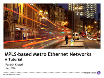
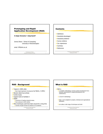
White Paper: Ethernet OAMframe is received by an OAM-enabled Ethernet MAC, it is passed to the OAM client forprocessing; such a frame is simply discarded if received by a MAC that does not supportlink-layer OAM. In any case, link-layer OAM frames are never forwarded.Since the IEEE link-layer OAM is generally used over a link between a service provider and acustomer, it defines two modes for OAM entities: active or passive. The elements of theprovider network (e.g. DSLAMs or provider Ethernet switches) operate in active mode, andcan exert control over the passive-mode devices (e.g. DSL modems or customer premisesswitches). Thus, the active-mode entity can send an LB command forcing the passive-modedevice into loopback mode, and query the configuration parameters of the passive-modedevice. However, the reverse is not possible. We shall see later that service OAM specifiesmore complex relationships, involving end points, intermediate points, and levels ofhierarchy.Link-layer OAM messages are sent in untagged slow protocol frames called OAM ProtocolData Units, or OAMPDUs. Slow protocols are protocols used to control operationalcharacteristics of the Ethernet device, such as the Link Aggregation Control Protocol (LACP,formerly known as 802.3ad) which also utilizes slow protocol frames. Slow protocols areslow in the sense that they are restricted in the number of protocol frames that may betransmitted per second (for OAMPDUs – no more than 10 frames per second), thusfacilitating software implementations of the OAM client. All slow protocols use Ethertype88-09, and link-layer OAM is differentiated by a sub-type of 03 that appears as the firstbyte of the MAC client payload. OAMPDUs are multicast to a specific multicast address thatis link-constrained, since OAMPDUs only traverse a single link, but are never forwarded bybridges or switches, even if these bridges do not implement OAM.OAMPDUs contain control and status information needed to monitor, test and troubleshootOAM-enabled links. This information is encoded using a major code followed by informationencoded in Type-Length-Value (TLV) format (see Figure 1). Many modern protocols use TLVsin order to permit protocol extensions. Proprietary (organization specific) OAM extensionsmay support enhanced capabilities, but will still be limited by the single-hop nature of EFMOAM.Figure 1 - EFM OAM Format 2006 RAD Data Communications Ltd.9
White Paper: Ethernet OAMThe best way to explain the capabilities of link-layer OAM is to enumerate the flags andcodes. Six codes are presently defined: Information Event notification Variable request and response Loopback control Organization-specific.Information code OAMPDUs are used for autodiscovery, heartbeat, and fault notification,making them the workhorse of link-layer OAM. Discovery is the procedure whereby OAMenabled entities discover each other and exchange information regarding their OAMcapabilities and configuration. The OAM capabilities may be used to determine whether it isworthwhile to run the OAM protocol. For example, this may be used for active-mode OAMsinterested only in loopback-capable peers. OAMPDUs must be sent at least once persecond; if there are no other pending messages, an information PDU with no informationTLVs is sent. Finally, although all OAMPDUs of all codes carry flags (see below), when anevent occurs that necessitates the immediate sending of a fault indication, an informationcode OAMPDU is always sent.Event notification OAM frames are used for reporting various link statistics such as thenumber of symbol errors that occurred during a specified period, or the running total offrames with errors since the OAM sublayer was last reset. Variable request frames are usedby service providers to obtain the customer’s configuration by requesting MIB variables.Variable response frames are returned by the customer in response to such requests. Onlyactive-mode entities may send request frames, and only passive-mode ones will returnresponse frames. Since delivery of any given Ethernet frame is not guaranteed (especiallyduring problematic network conditions when OAM is most valuable), event OAMPDUs maybe sent several times to increase the likelihood of reception.Loopback control OAM frames are used by an active-mode OAM entity to enable or disableintrusive loopback in the remote passive-mode device. The loopback function is an optionalfeature that may be implemented in software or hardware. When enabled, all frames exceptOAMPDUs and PAUSEs are returned to their source on the same port instead of beingforwarded as usual. At any time during loopback mode, statistics from local and remoteOAM clients may be queried.10 2006 RAD Data Communications Ltd.
White Paper: Ethernet OAMFlags are contained in every OAMPDU in order to expedite notification of critical events andto continuously monitor for slowly deteriorating performance. These flags signal whetherthe remote OAM entity has completed the discovery phase and is ready to receive OAMmessages. The defects that can be indicated are link fault, dying gasp, and otherunspecified critical events. The link fault flag is set when the PHY receiver detects a loss ofsignal, making this flag a reverse defect indication (RDI). For the duration of the link fault,this flag remains set in all OAMPDUs, and empty information OAMPDUs are sent once persecond. Dying gasp is a notification sent by a device about to operationally fail (due topower failure, having been reset, etc.). It originated in the xDSL modem world, and can beused to inform the service provider of imminent failure of the remote device. Any othererror condition that does not result in rebooting of the device is indicated by the criticalerror catch-all flag.Y.1731/802.1ag Service OAMLink-layer OAM allows detection of faults on an EFM link. While this is a useful feature,service providers are in need of the ability to fully monitor a customer’s end-to-endEthernet service. This monitoring ability should be agnostic to the layers supporting thisservice, which may be EFM (i.e. DSL or native Ethernet fiber), but may also be other servicessuch as SONET, ATM, or MPLS (“Ethernet pseudowires”). In addition, when several serviceproviders and/or network operators are involved, each needs to separately monitor thelayer for which it is responsible.When an Ethernet service is first initiated, end-to-end path integrity needs to be verified.Similarly, if some failure is detected, the service provider needs to quickly identify thecustomers that are affected, and what rerouting can be performed. These functions couldbe done using IP-based tools, but (as discussed above) if the service being provided isEthernet, the best approach is to have independent Ethernet-specific OAM.Ethernet service OAM defines a hierarchy of up to eight OAM levels, allowing users, serviceproviders and operators to run independent OAMs at their own level. By default, users areallocated three levels, service providers two levels, and operators three levels. OAM framesbelonging to higher levels are transparently forwarded by lower level devices (e.g. user OAMframes are forwarded by service provider switches). 2006 RAD Data Communications Ltd.11
White Paper: Ethernet OAMService OAM for Ethernet builds on general principles developed over time for TDM, SONET,ATM, and most recently MPLS networks, but Ethernet presents several new challenges.First, previous packet-based OAM protocols were for connection-oriented networks, whileEthernet is connectionless. Hence mechanisms that protect well-defined paths need to beextended to connectionless flows. Second, previous OAM protocols were mainly developedfor point-to-point connectivity, while Ethernet is inherently multipoint-to-multipoint. Third,even among connectionless networks Ethernet’s behavior can be mischievous, at timessending frames to unexpected places. This is problematic since OAMs should not leak fromone OAM domain to another, and customers (or other service providers) should not be ableto interfere with proper service OAM operation.Solving all of these problems requires defining a number of new concepts, and although theIEEE and ITU don’t always give these concepts the same names, they are in agreement as totheir intentions. Since Y.1731 has been finalized while 802.1ag is still in progress, we shallmainly use ITU terminology here. Y.1731 defines a maintenance entity (ME) that requiresmanagement. Some examples of these entities are the entire Ethernet network betweentwo customer switches, or the Ethernet network in the administrative domain of a singleservice provider, or even a single Ethernet link. Thus MEs can be nested, with link MEsinternal to service provider, and MEs of successive providers internal to the customer endto-end ME.In order to capture the multipoint-to-multipoint nature of Ethernet, MEs are grouped intoME groups (MEGs, referred to as Maintenance Associations or MAs in IEEE language). Amultipoint-to-multipoint Ethernet network with N end-points has N(N-1)/2 MEs, while apoint-to-point connection has only one. In order to enable detection of incorrectconnectivity, each MEG is given a unique ID, and OAM messages specify the MEG ID forwhich the message is intended.At the ends of managed entities we find MEG End Points (MEPs), which are the functionsthat generate and process OAM frames to monitor and maintain the ME. There may also beMEG Intermediate Points (MIPs) that can respond to OAM messages, but cannot originatethem. For
White Paper By Yaakov (Jonathan) Stein, Chief Scientist RAD Data Communications. Abstract Until recently Ethernet lacked OAM functionality like that found in in SONET/SDH or ATM, and therefore was not characterized as "carrier class." Now it has acquired two types of OAM, one developed by the ITU and IEEE