Transcription
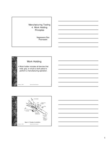
LOCATING COMPONENTSAdjustable Jack Screws. 212Adjustable Locating Buttons. 212Alloy Steel Pull Dowel Pins.198–199Bullet Nose Dowels. 219Bullet Nose Pins. 220Drift Handles. 213Fixture Jacks. 212Fixture Keys, Sine.214–215Fixture Keys, Standard. 213Flat Feet. 210Jig Feet.209Jig Legs. 210Jig Pins. 203Lanyards. 203Locating Pins.216–217Locating Pin Liners. 218Locating Pin Lock Screws. 218L-Pins. 202Pilot Locating Pins. 219Precision Expanding Dowels. 201Pull Dowel Pins, Alloy Steel.198–199Pull Dowels.200Rest Buttons. 205–207Rest Buttons, Carbide Insert. 207Rest Buttons, Threaded.206Rest Pads.208Screws, Adjustable Jack. 212Slotted Locator Bushings.204Stripper Bolts, Kwik-Strip.196–197Tooling/Inspection Balls.221–223T-Pins. 202Work Support Jacks, Manual.211LOC ATING COMPONENTSLocating Components195
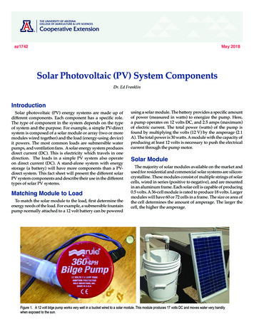
LOCATING COMPONENTSWORKHOLDING SOLUTIONS GROUPKwik-Strip Stripper Bolts A New Perspective on Stripper PlatesToday's more complex dies require more time to service.The advantage of time saving devices such as ball and rolllock punches is minimized unless the stripper plate can beremoved first.The patented Jergens Kwik-Strip Stripper Bolts providean inexpensive, simple method of stripper plate removal.The stripper can be removed with the die still mountedin the press!InstallationStep 1: Drill a through hole 1/32" larger than the nominalbody diameter of the bolt to be used.LOC ATING COMPONENTSStep 2: Using a Jergens Drill Jig, drill the auxiliary 1/4" hole.The 1/4" hole may be located radially at any positionon the periphery of the body hole. Drill the 1/4" holeslightly deeper than the proposed counterbore.Step 3: Using a standard counterboring tool, counterbore torequired depth. See counterbore selection chart forproper size.Step 4: Drill and counterbore the stripper plate for a sockethead cap screw.Step 1Step 2Installation in Existing DiesTo convert an existing die for use with Jergens Kwik-StripStripper Bolts, simply mill a 1/4" slot down the side of the strippercounterbore, then drill and counterbore the stripper plate.If the same size thread must be maintained, the through holeand counterbore in the punch holder will have to be increased.Step 4Disassembly in the PressBlock the stripper plate in position, remove the cap screwsusing a hex wrench, then carefully remove stripper plate.Replace stripper plate after completion of required service.196Jergens, Inc. 15700 S. Waterloo Road Cleveland, Ohio 44110-3898 USAStep 3
LOCATING COMPONENTSWORKHOLDING SOLUTIONS GROUPKwik-Strip Stripper Bolts Material: Alloy Steel Heat Treat: Rc 32-36 Available in Fixture Pro Design SoftwareSelection of SizesSize selections should be based upon thread size. For example,if your application calls for a 1/2" stripper bolt (with a 3/8" thread)use a 5/8" Kwik-Strip bolt (with a 3/8" thread). Kwik-Strip bolts may beshortened by 1/4" and still have sufficient thread depth for the cap screw.Part /85/85/85/85/85/85/83/43/43/43/43/43/43/422 1/233 1/244 1/2522 1/233 1/244 1/2522 1/233 1/244 .534.53457/6457/6457/6457/6457/6457/6457/641 1/641 1/641 1/641 1/641 1/641 1/641 1/641 9/641 9/641 9/641 9/641 9/641 9/641 11111111111 1/81 1/81 1/81 1/81 1/81 1/81 1/81 1/41 1/41 1/41 1/41 1/41 1/41 1/2-131/2-131/2-131/2-131/2-131/2-13Phone: 877-426-2504 Fax: 1 216-481-6193 E-mail: workholding@jergensinc.com .23.27.32.36.41.45.26.33.39.46.52.59.65LOC ATING COMPONENTS 197
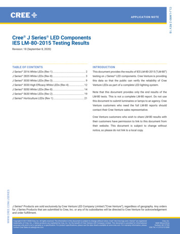
LOCATING COMPONENTSWORKHOLDING SOLUTIONS GROUPAlloy Steel Pull Dowel PinsJergens Offers 3 Styles of Precision Ground Pull DowelsSpiral Groove(Grooves Help to Relieve Trapped Air)Features, Applications & Benefits Internally threaded hole allowsremoval of pull dowels with astandard screw. Standard Round Pull Dowelsare typically used in applicationsfeaturing a through hole. Spiral Groove PullDowels feature a groovecut to allow trapped airto be released. Flat Vent Pull Dowels feature aground flat on one side to releasetrapped air.LOC ATING COMPONENTSFlat Vent(Ground Flat Helps to Relieve Trapped Air) Spiral Groove and Flat Vent PullDowels are typically used in blindhole applications. All of Jergens Precision GroundPull Dowels are constructed ofheat treated alloy steel. Standard Round(Non-Vented) 198Jergens, Inc. 15700 S. Waterloo Road Cleveland, Ohio 44110-3898 USA
LOCATING COMPONENTSWORKHOLDING SOLUTIONS GROUPPrecision Ground Pull 831849318503185131856*31852*31853*31854*31855*Flat VentStandard RoundNominalActualLengthInternal 3/422-1/2341-3/422-1/2348 - 328 - 328 - 328 - 328 - 328 - 328 - 328 - 328 - 3210 - 3210 - 3210 - 3210 - 3210 - 3210 - 3210 - 3210 - 3210 - 3210 - 3210 - 3210 - 3210 - 3210 - 3210 - 3210 - 321/4 - 201/4 - 201/4 - 201/4 - 201/4 - 201/4 - 201/4 - 201/4 - 201/4 - 201/4 - 201/4 - 201/4 - 201/4 - 201/4 - 201/4 - 201/4 - 201/4 - 201/4 - 201/4 - 201/4 - 201/4 - 205/16 - 185/16 - 185/16 - 185/16 - 185/16 - 185/16 - 185/16 - 185/16 - 185/16 - 185/16 - 185/16 - 18Technical DataMaterial:Alloy SteelLength Tolerance: .010"Core Hardness:47 - 58 Rockwell CDiameter Tolerance: .0001"Surface Hardness:60 - 64 Rockwell CRecommended Hole Size:.0005" under Nom. Dia.Surface Finish:8 Micro-InchSpecification:ASME B18.8.2Spiral GrooveLOC ATING COMPONENTSSpiral GrooveFlat VentStandard Round*3/8-16 Internal ThreadPhone: 877-426-2504 Fax: 1 216-481-6193 E-mail: workholding@jergensinc.com www.jergensinc.com199
LOCATING COMPONENTSWORKHOLDING SOLUTIONS GROUPPull DowelsMetric Material: Low Carbon Steel Heat Treat: Case Hardened Available in Fixture Pro Design Software Flat ground on the side for airrelease in blind holes.LOC ATING 2030402030405070203040M5 x 1.0M5 x 1.0M5 x 1.0M6 x 1.0M6 x 1.0M6 x 1.0M6 x 1.0M6 x 1.0M6 x 1.0M6 x 1.0M6 x 1.0PartNumberALT317751250M6 x 1.0317761260M6 x 1.0317771270M6 x 1.0317801640M8 x 1.25317821650M8 x 1.25317831660M8 x 1.25317841670M8 x 1.25317872050M10 x 1.6317882060M10 x 1.6317892070M10 x 1.6Button head screw not included.Jergens, Inc. 15700 S. Waterloo Road Cleveland, Ohio 44110-3898 USA
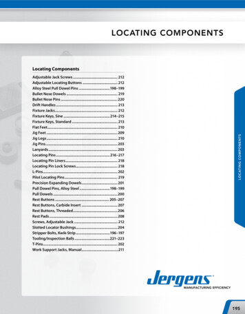
LOCATING COMPONENTSWORKHOLDING SOLUTIONS GROUPPrecision Expanding Dowels Material: Alloy Steel, case hardened to 50-55 Rockwell C Self-Centering and Repeatable within /- 0.0005" (0.013mm) Top and bottom half of dowel expand seperately PatentedBL1LAInch294023/83/4Hex Key SizesRecommendedHole DiameterA DiameterB DiameterL1BottomTop 0.001/-0.000" 0.000/-0.001" 0.000/-0.010" 0.005"Step 1Step 81 1/40.6250.6240.6201.1623/167/32294053/41 951.7583/81/2NominalDiameter(mm)NominalLength (L)(mm)RecommendedHole DiameterA DiameterB DiameterL1BottomTop 0.025/-0.00mm 0.00/-0.025mm 0.00/-0.25mm 0.13mmStep 1Step 21020109.989.8817.4534MetricPartNumber29451Hex Key 19.9819.8935.3168EXPANDIN1-LOC ATING COMPONENTSNominalNominalDiameterLength (L)InchInchEXPANDING DOWELS29401 1-8-101/41/2PartNumberInstallation InstructionsStep 1Step 2Remove the top screw, insertthe dowel into the locatinghole of the first part, andexpand the bottom half witha hex wrench.Replace the top screw,slide the locating hole ofthe second part over thedowel and expandtop half with a hex wrench.Phone: 877-426-2504 Fax: 1 216-481-6193 E-mail: workholding@jergensinc.com www.jergensinc.com201
LOCATING COMPONENTSWORKHOLDING SOLUTIONS GROUPL-Pins and T-PinsJergens L-Pins and T-Pins are precision ground locatingdevices for aligning workpieces in jigs or fixtures. Eachpin has a 1/8" diameter hole in the handle for attachingthe nylon covered lanyard shown on page 203.Part Number Material: Heat Treated Steel Finish: Black Oxide Available in Fixture Pro Design Software LOC ATING 5.7502 1/236362346323 1/2646464646661 1/22 1/22 1/22 1/22 1/22 1/22 1/22 1/22 1/22 1/22 1/2333 1/23 1/23 1/23 1/23 1/23 1/23 1/23 1/23 1/23 /21/29/169/165/85/85/85/87/87/8MetricPart , Inc. 15700 S. Waterloo Road Cleveland, Ohio 44110-3898 USA
LOCATING COMPONENTSWORKHOLDING SOLUTIONS GROUPJig PinsFJig Pins are precision ground locating devices. The straight handle styleDcomes with a hole for easy attachment of a lanyard. The T-handle style can1/2"be converted to an L-handlestyle by tapping the roll pin with a hammer.D1/2"ØEØEC Material: Low Carbon Steel Finish: Black Oxide Heat Treat: Case Hardened Rc 58-62 (pin only)CStraight Handle Jig PinBStraightHandleJig PinBPartNumberABCDE24101.2500 2 1/224102 .000 .3125 2 1/2ØA-.0005 .375024103424104.50003 .000ØA -.00052 5/82 5/82 5/82 5/81/29/165/83/41/41/41/45/16FDD1/2"1/2"ØECCT- Handle Jig PinPartNumberABCDEFBBT-Handle .000Jig PinsØA -.0005Lanyards24111241122411324114.2500 2 1/2.3125 2 1/2.37504.500032 5/82 5/82 5/82 5/81/29/165/83/41/41/41/45/162333 .000ØA -.0005LOC ATING COMPONENTSØE To attach lanyard to L or T Pins order Split Ring 890000 To permanently attach Lanyard to L or T Pins add -C to Lanyard part number For Lanyard &Tab drawings see Kwik-Lok Pins in Specialty Fastener Solutions Catalog or Master Catalog Ordering Lanyards When Supplied Separately Without PinsTable 1 Tab Hole SizeLanyards with TabsLengthinch mmRound 102152203254305406508610Oval TabSubstitute the asterisk (*) with theproper hole size letter from Table 1.Tab Mounting
Slotted Locator Bushings. 204 Stripper Bolts, Kwik-Strip. 196–197 Tooling/Inspection Balls . 221–223 T-Pins.202