Transcription
11/28/201810G Ethernet Over Structured Copper Cabling - White Paper by SiemonIT Infrastructure SolutionsNote:The following technical article was current at the time it was published. However, due to changing technologiesand standards updates, some of the information contained in this article may no longer be accurate or up to date.10G Ethernet Over Structured Copper CablingAbstractRecent market research points to an increased demand in Internet traffic. New applications coupled with thegrowth of Internet users is driving the need for increased bandwidth. One such technology that will address thisdemand is 10 Gb/s Ethernet over structured copper cabling systems. An overview of current market trends andtechnological challenges related to this 10G technology will be reviewed. The primary focus of this paper willinclude a review of the key challenges facing the structured copper cabling media required to support this newtechnology.The copper media infrastructure supporting 10 Gb/s Ethernet will need to be characterized. This characterizationwill involve an understanding of key areas, which include, a review of the structured cabling media transmissioncharacteristics, bandwidth requirements and length limitations across various cabling types.An understanding of theoretical channel bounds will be investigated using Shannon’s equation for upper channelbound analysis. A discussion of key proposals outlining the performance requirements for structured coppercabling to support this new technology will be reviewed. A key understanding of the channel characteristicscomprising the media is critical for overall system design.Examples detailing the transmission characteristics for three distinct cabling types will be provided. These cablingtypes include unshielded twisted pairs (U/UTP), twisted pairs with overall foil (F/UTP), and twisted pairs withindividual foils and overall screen (S/FTP).Examples displaying theoretical Shannon capacity using transmission data for different structured cabling typeswill be provided. Simulations will show dependencies on how a cabling system’s channel characteristics, such asalien NEXT, affect theoretical channel bounds.Keywords:10 Gb/s Ethernet, Insertion Loss, Return Loss, Near End Crosstalk (NEXT), Far End Crosstalk (FEXT), EqualLevel Far End Crosstalk (ELFEXT), Alien Crosstalk (ANEXT), Powersum, U/UTP, F/UTP, S/FTP, ShannonCapacity1. IntroductionFor corporations, networked PC’s have helped to streamline operations, improve profitability, and increasecustomer satisfaction. In today’s global marketplace, it is virtually mandatory to be electronically connected to keysuppliers and customers.A review of the 10 Gb/s Ethernet technology will be provided with a main focus on the cabling objectives. Areview of cabling specifications will be provided along with measurement data for key cabling classes. Finally,http://www.siemon.com/us/white papers/04-12-22 10G Ethernet Over Structured Copper Cabling.asp1/15
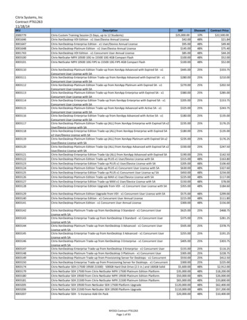
11/28/201810G Ethernet Over Structured Copper Cabling - White Paper by Siemontheoretical Shannon capacity simulation results will be provided that will display the technical feasibility ofachieving 10 Gb/s Ethernet over structured copper cabling.2. Recent Market TrendsSignificant demand for bandwidth has grown dramatically as a result of the way business environments are usingnetworking to improve operations. The development of enhanced client/server applications, along with newapplications that converge voice, data, and video have also helped fuel this demand. Greater and greater demandsare being placed on networks as the performance of hardware and software components of PC’s becomes greater.This complexity, along with the growth of business environments, increases the size and usage of the networks.Network performance typically trends downward as a result.The high demand for bandwidth has resulted in an increased demand for higher speed switches and routers. Figure1 provides a graphical plot of market share percentage for the worldwide LAN switch market. Three key switchtechnologies are shown: 10/100 Mbps Ethernet, Gigabit Ethernet, and 10 Gigabit Ethernet. The projected forecastover the next three years shows an increase in market share for both the Gigabit Ethernet and 10 Gigabit Ethernetswitches.Figure 1. Worldwide LAN switch marketTo help fill this gap, the IEEE has formed a task force to develop a standard for 10 Gb/s Ethernet over structuredcopper cabling. The goal of the standard is to develop 10 Gb/s Ethernet products that would currently work overinstalled horizontal structured cabling with certain length limitations. The present timeline target for thecompletion of the standard is July 2006.3. Overview of 10GBASE-T Ethernet3.1 ObjectivesThe 10GBASE-T task force (formally known as IEEE 802.3an ) group’s initial goal was to develop 10 GigabitEthernet that would operate over horizontal, structured, twisted-pair cabling. Several of the key objectives that thegroup would need to work on would include:Preserving the 802.3/Ethernet frame and size formats at the MAC interfaceSupport a speed of 10 Gb/s at the MAC interfaceSupport full duplex operationSupport operation over a 4 connector structured 4-pair, twisted-pair copper cabling for all supporteddistancesSatisfy CISPR/FCC “Class A” emissions requirementshttp://www.siemon.com/us/white papers/04-12-22 10G Ethernet Over Structured Copper Cabling.asp2/15
11/28/201810G Ethernet Over Structured Copper Cabling - White Paper by SiemonSupport a BER of 10-12 on all supported distances and classes3.1.1 10GBASE-T Cabling ObjectivesThe main cabling objectives for the 10GBASE-T task force are to:Support operation over 4-connector structured 4-pair twisted-pair copper cabling for all supported distancesand classesDefine a single 10 Gb/s PHY that would support links of:At least 100m on four-pair Class F/Category 7 balanced copper cablingAt least 55m to 100m on four pair Class E/Category 6 balanced copper cablingSatisfy CISPR/FCC “Class A” emissions requirements3.2 ApplicationsTwo key critical application environments that 10 Gb/s Ethernet would help to support would be the data centerenvironment and environments containing structured copper cabling.As indicated by market trends, faster networks will demand greater bandwidth network capacity. The data centerwill be the primary environment helping to support new applications relating to data storage and server clustering.10GBASE-T is also competing against two additional technologies (10GBASE Fiber and 10GBASE-CX4). Therelative potential advantage that 10 Gb/s Ethernet will have over 10GBASE Fiber will be a relative cost reduction.The potential advantage that 10 Gb/s Ethernet will have over 10GBASE-CX4 will be the ability to transmit over agreater physical distance. Presently, the 10GBASE-CX4 standard operates over a physical distance of 15m.If history is any indication of future trends, applications developed for the data center environment will eventuallymigrate to the desktop. Therefore, the ability to address this goal is also important to the 10GBASE-T task forcegroup.3.3 Relative Cost AnalysisThe relative costs of this technology as compared to other technologies are also important for market acceptance.Figure 2 displays the relative cost differential between the 10 Gb/s Ethernet vs. 1 Gb/s Ethernet. According torecent projections [3], the absolute cost differentials between 10 Gb/s copper and 1 Gb/s copper will be estimatedat a factor of 8-9 times and is projected to trend to a factor of 2-3 times by year 2008. Figure 3 displays projectedtrends comparing 10 Gb/s copper vs. 10GBASE Fiber. The trend indicates an absolute cost target of 0.6x fibertrending towards 0.15x by year 2008.http://www.siemon.com/us/white papers/04-12-22 10G Ethernet Over Structured Copper Cabling.asp3/15
11/28/201810G Ethernet Over Structured Copper Cabling - White Paper by SiemonFigure 2. 1G vs. 10G Relative Cost TargetFigure 3. 10G Fiber vs. 10G Relative Cost Target4. Structured Cabling CharacterizationAn understanding of the key electrical transmission parameters of structured cabling is critical for theunderstanding of technical feasibility of transmitting 10 Gb/s over structured copper cabling. The characterizationfalls into two categories: (1) internal channel parameters and (2) external channel parameters. A discussion of thechannel topology will be provided prior to the discussion of key electrical parameter characterization.One example of a horizontal cabling model is the cross-connect model, as shown in Figure 4. The topology of thismodel is comprised of three main elements: patch cords, connecting hardware, and horizontal cable. This model iscomprised of four connection points with a maximum total channel length of 100m (328 ft).http://www.siemon.com/us/white papers/04-12-22 10G Ethernet Over Structured Copper Cabling.asp4/15
11/28/201810G Ethernet Over Structured Copper Cabling - White Paper by SiemonFigure 4. Cross-Connect Structured Cabling ModelThe key internal channel parameters for a specific type of cabling are: insertion loss (IL), return loss (RL), near endcrosstalk (NEXT), and equal level far end crosstalk (ELFEXT). A review of each parameter will be provided.Insertion loss is a measure of signal loss that occurs from transmitter to receiver. Insertion loss is typicallyexpressed as a ratio of signal power at the receiver compared to the initial launch power, expressed in decibels.Return loss is a measure of how much signal gets reflected back to the source due to impedance variations in thechannel, expressed in decibels. The IL and RL parameters are illustrated in Figure 5. For simplicity, figure 5displays only one twisted pair. In this example, key factors affecting the channel insertion loss may includeconductor size, material types for conductor insulation and jacket, frequency bandwidth, number of connectors,and physical length. Key factors affecting RL performance may include variations in twist rates for a twisted pairand discontinuities due to impedance mismatches between components in the channel.Figure 5. Insertion Loss and Return LossNear end crosstalk is a measure of unwanted signal coupling between pairs in the same channel when a disturbingsignal is sent from a transceiver on the same end, expressed in decibels.The effect of multiple active pairs in a channel is described using “powersum crosstalk”. In a full duplexenvironment, transceivers at both ends of a channel are generating signals simultaneously. Powersum crosstalk is amathematical relationship, which computes the total noise coupling from all adjacent pairs to a particular pair. Forexample, the total receive noise that is coupled onto a random twisted pair results from the unwanted noisegenerated from the other three remaining pairs at a given point in time.Far end crosstalk is a measure of unwanted signal coupling between pairs in the same channel when a disturbingsignal is sent from one end and received by the transceiver on the opposing end of the channel, expressed indecibels.The ELFEXT parameter for a particular pair combination is a calculation that takes into account both the FEXTcoupled noise and the insertion loss of the channel under question.Mathematically, it is expressed as:ELFEXT FEXT-IL(1)http://www.siemon.com/us/white papers/04-12-22 10G Ethernet Over Structured Copper Cabling.asp5/15
11/28/201810G Ethernet Over Structured Copper Cabling - White Paper by SiemonPhysical channel length may vary across multiple channels; therefore the ELFEXT parameter is a useful measurefor analyzing the far end noise generated without the dependence of insertion loss. The PSELFEXT parameter maybe computed by substituting PSFEXT for FEXT in equation 1.Figure 6 provides a graphical representation of both the NEXT and FEXT unwanted noise coupling. In this figure,the NEXT coupling occurs when a signal generated on the blue pair couples over to an orange pair on the same end(i.e. Near end). The FEXT coupling occurs when a signal generated on the blue pair couples over to an orange pairon the opposing end of the channel. The powersum NEXT coupling for the brown pair in this figure may becomputed by summing up the unwanted noise coupling from the three remaining pairs (i.e. blue, orange, and greenpairs) on the same end.Figure 6. NEXT and FEXT lossUp to now, the effects of in-channel parameters have been reviewed. This next section will review the criticalexternal channel parameters.Alien crosstalk is a measure of unwanted signal coupling from one or more pairs from one channel to aneighboring adjacent channel, expressed in decibels.Alien crosstalk is a very difficult channel parameter to model due to its random statistical nature. Presentationsgiven in the 10GBASE-T task force have identified alien crosstalk to be the most dominant noise source. Unlikeother noise impairments, alien crosstalk is very difficult to mitigate using advanced digital signal processing (DSP)algorithms due to its random statistical nature. The inability of mitigating alien crosstalk noise greatly affectstheoretical capacity targets.Figure 7 provides a graphical representation of alien crosstalk coupling from one channel to an adjacent channel. Inthis example, the effects of alien crosstalk are observed when the signal in one pair of one channel (e.g. channel A:blue pair) couples onto a pair of a second neighboring channel (e.g. channel B: blue pair). As with the NEXTparameter, the coupling effects caused by full duplex transmission can best be described using the powersummathematical relationship. In the case when two neighboring channels are running side by side, the total powersumANEXT that a particular pair observes (e.g. channel B: blue pair) is attributable to signals generated on all pairs ofthe neighboring channel (e.g. channel A: blue, orange, green, and brown pairs).Figure 7. Alien NEXT losshttp://www.siemon.com/us/white papers/04-12-22 10G Ethernet Over Structured Copper Cabling.asp6/15
11/28/201810G Ethernet Over Structured Copper Cabling - White Paper by Siemon5. 10GBASE-T Cabling5.1 Cabling TypesAn understanding of the various structured cabling types available as underlying media for the 10 Gb/s standardwill be reviewed. The ISO/IEC cabling standard [1] provides definitions for the various cabling types. Figure 8provides an illustration of three of these various cabling class constructions.The designation U/UTP defines a balanced cable type in which four twisted-pair conductors are surrounded by acable sheath. The designation F/UTP defines a balanced cable type in which an overall metal foil encloses all fourtwisted conductor pairs and then the metal foil is surrounded by a cable sheath. The designation S/FTP defines abalanced cable type in which each of the four twisted conductor pairs are enclosed by a foil screen and then allpairs are surrounded by a braid screen and an overall cable sheath.Figure 8. Cabling Types5.2 SpecificationsOne of the key objectives of the 10GBASE-T standard is to support copper media that is representative of eitherclass E or class F structured cabling. Presently, the Class E cabling specification (also referred to as category 6)defines balanced cabling characteristics over a maximum bandwidth of 250 MHz. The Class F cablingspecification (also referred to as category 7 cabling) defines balanced cabling characteristics over a maximumbandwidth of 600 MHz.In order to address the technical feasibility of physical layer device (PHY) proposals, the 10GBASE-T group beganworking on a draft document that would outline electrical characteristics of the structured cabling listed in theobjectives. The ongoing results of this effort are documented in a key supporting draft document: TIA/EIA TSB155 D1.0. This draft document will eventually work it’s way into the final draft of the 10GBASE-T specification.The draft document provides minimum specifications for both internal and external cabling parameters.Figure 9 provides a summary chart of curves that represent the minimum specifications required to help support theminimum length objectives of 55m over class E cabling.http://www.siemon.com/us/white papers/04-12-22 10G Ethernet Over Structured Copper Cabling.asp7/15
11/28/201810G Ethernet Over Structured Copper Cabling - White Paper by SiemonFigure 9. Specifications for 55m class E cabling5.2.1 ConstraintsOne of the key cabling objectives for the 10GBASE-T standard is to operate over current installed class E cabling.Presently, the current class E specification must address two main technical gaps. The first of these gaps is thefrequency bandwidth. The current class E specification only specifies requirements to 250 MHz. The second gap,which will also apply to the class F specification, are requirements for alien crosstalk characterization.The 10GBASE-T task force has agreed that an upper frequency bandwidth of 500 MHz will be sufficient forachieving the data rate of 10 Gb/s over a corresponding channel. The 10GBASE-T group has conducted asignificant amount of work and key presentations indicate that insertion loss and alien crosstalk are two of the mostsignificant cabling parameters that will affect Shannon capacity.The U/UTP class E cabling type has a higher susceptibility to alien crosstalk coupling. Therefore, lengthrestrictions have been placed on present class E U/UTP cabling. Simulations have resulted in a theoretical physicallength reach of 55m given a set of worst-case specifications, as shown in Figure 9.Figure 10 displays a summary of curves for insertion loss and powersum alien crosstalk, as referenced in draftdocument TIA/EIA TSB-155 D1.0. The purpose of these curves is to show what support levels are required toachieve physical channel length objectives of 55m and 100m, respectively. Any future cabling that is developed tomeet these powersum alien crosstalk requirements provided below would also meet the length objective of 100m.It’s important to note that the cabling community, through technical cabling working groups, such as the TIA(telecommunication industry association) and ISO (international standards organization) are working towards thedevelopment of a new “augmented” class E specification that will help to define cabling characteristics over amaximum of 100m.http://www.siemon.com/us/white papers/04-12-22 10G Ethernet Over Structured Copper Cabling.asp8/15
11/28/201810G Ethernet Over Structured Copper Cabling - White Paper by SiemonFigure 10. Insertion loss and PS ANEXT Limits6. Cabling PerformanceA summary of key electrical performance data has been collected and summarized for three key cabling types,class E U/UTP, class E F/UTP, and class F S/FTP. Performance data was recorded within the 1-500 MHzbandwidth. Performance data was compared against specifications called out for in TIA/EIA TSB-155 D1.0 draftdocument.Figure 11 provides a summary of the insertion loss performance of a typical 100m channel for each respectivecabling type. An analysis of the insertion loss data beyond 100 MHz indicates that the S/FTP and F/UTP channelsdisplay a significant improvement in signal strength over the U/UTP channel. At 500 MHz, the S/FTP channelexhibits approximately 7.4 dB lower losses when compared against the U/UTP channel. The level of signalstrength observed by a receiver is extremely important in determining the signal to noise ratio of the system. Allelse being equal, a stronger signal will translate to a higher signal to noise ratio, resulting in a greater theoreticalchannel capacity.Figure 11. Insertion loss performance dataFigure 12 provides a summary of the return loss performance of a typical 100m channel for each respective cablingtype. An analysis of the return loss performance across all three cabling types indicates that the worst case cablingwould support return loss levels of approximately –12 dB (based on a worst case frequency point analysis). Thehttp://www.siemon.com/us/white papers/04-12-22 10G Ethernet Over Structured Copper Cabling.asp9/15
11/28/201810G Ethernet Over Structured Copper Cabling - White Paper by Siemonbest case cabling would support return loss levels of approximately –18 dB. The –12 dB return loss level wouldapproximately result in a voltage ratio of 25%. For example, if a 1V pk-pk signal was launched into the cabling,the transmitter would observe a reflected signal of 0.25V pk-pk. Better matched components, result in lowerperformance levels for return loss. These corresponding lower levels result in less reflected energy back to thesource.Figure 12. Return loss performance dataFigure 13 provides a summary of the powersum NEXT performance of a typical 100m channel for each respectivecabling type. Similar levels of crosstalk coupling are observed for the U/UTP and F/UTP channels. The S/FTPchannel exhibits far lower levels of crosstalk coupling. At 500 MHz, an analysis of the S/FTP data indicates a 27.6dB reduction in noise level as compared to the U/UTP cabling. This magnitude represents approximately 95.8%reduction in noise over the preceding level. The impact of lowering noise in a system helps to increase the signal tonoise ratio, resulting in greater channel capacity.Figure 13. PS NEXT loss performance dataFigure 14 provides a summary of the powersum FEXT performance of a typical 100m channel for each respectivecabling type. As a signal transverses down a particular pair, the insertion loss magnitude of the signal will increaseover greater lengths. These attenuated signals at the far end of a channel will impose less noise coupling thanhttp://www.siemon.com/us/white papers/04-12-22 10G Ethernet Over Structured Copper Cabling.asp10/15
11/28/201810G Ethernet Over Structured Copper Cabling - White Paper by Siemonsignals that couple at the near end of a channel. As a result, PS FEXT noise magnitude levels are lower whencompared to PS NEXT noise levels.Figure 14. PS FEXT loss performance dataFigure 15 provides a summary of the powersum alien NEXT performance of a typical 100m channel for eachrespective cabling type. The shielding properties of the F/UTP and S/FTP channels result in very low powersumalien crosstalk coupling. This advantage results in the ability to transmit over a greater distance as compared withchannels that do not exhibit low powersum alien crosstalk coupling. At 500 MHz, an analysis of the S/FTP dataindicates a 42.9 dB reduction in noise level as compared to the U/UTP cabling. This magnitude representsapproximately 99.3% reduction in noise over the preceding level.Figure 15. PS Alien NEXT loss performance data7. Shannon Capacity and Simulation Results7.1 Review of Shannon CapacityClaude Shannon developed a formula to compute maximum channel capacity (bits/sec). Shannon’s equationprovides a benchmark against which the performance of a practical communication system may be measured.Shannon’s formula states:http://www.siemon.com/us/white papers/04-12-22 10G Ethernet Over Structured Copper Cabling.asp11/15
11/28/201810G Ethernet Over Structured Copper Cabling - White Paper by SiemonC W * log 2 (1 (S/N))(2)Where:C capacity of the channel (bits/sec)W bandwidth of the channel (Hz)S total signal power (dB)N total noise power (dB)S/N signal to noise ratioShannon’s equation provides us with the background to determine the theoretical channel capacity of an underlyingmedia. The key components of Shannon’s equation are bandwidth, signal, and noise components. A description ofeach component will be provided.The bandwidth value for the channel simulation was based on a maximum bandwidth of 500 MHz. The total signalpower (S), as observed by the receiver, is expressed as:S S i IL(3)Where:S i input signal power spectral density (PSD)IL insertion loss of the channel (dB)One of the key components in determining the overall signal strength is the associated loss of the cabling media.All other factors being equal, a shorter channel length results in a lower cabling insertion loss. This results in ahigher signal to noise ratio as observed by the receiver.Several noise sources exist in the copper communication channel. These noise sources include return loss, powersum NEXT, power sum FEXT, powersum alien NEXT, and background noise. Recent advances in DSP algorithmsallow for the further cancellation of noise sources. Stated mathematically, a random noise source takes thefollowing form:Noise j S i Noise Cabling – Cancel DSP(4)Where:Noise j the noise sourceS i input signal power spectral density (PSD)Noise Cabling noise component of a cabling parameterCancel DSP a value, expressed in dB, that represents the level of projected cancellation based on DSPalgorithms.The total noise power in the simulation is then determined by summing the individual noise source powers. Statedin equation form:(5)Once the total signal and noise components are computed, the resultant channel capacity is computed usingequation 2.7.2 Simulation ResultsRecent developments in the 10GBASE-T task force meetings have resulted in the approval for a baseband PAMmodulation strategy. Based on the modulation architectures brought forward, the maximum bandwidth of thehttp://www.siemon.com/us/white papers/04-12-22 10G Ethernet Over Structured Copper Cabling.asp12/15
11/28/201810G Ethernet Over Structured Copper Cabling - White Paper by Siemoncabling system required to support these modulation codes was selected to be 500 MHz.As stated in equation 3, the total signal power is dependent on the insertion loss for a particular cabling type (ref:Figure 11). Higher losses result in a weaker signal being detected by a receiver. This in turn would result in a lowersignal to noise ratio. The magnitude of the input signal power spectral density remained constant for allsimulations. This constant term is dependent on the transmit power level and the symbol rate.Several noise sources were factored into the simulations. These factors included background noise, return loss, PSNEXT, PS FEXT, and powersum alien NEXT. A key expert contribution [5] has indicated that several key noisesources may be canceled further using advanced DSP algorithms. The simulations factored in cancellation levelsfor PS NEXT, PS FEXT, and RL. The magnitude of these levels included: 40 dB (PS NEXT), 25 dB (PS FEXT),and 55 dB (Return loss). The random statistical nature of the powersum alien crosstalk parameter makes it verydifficult to model and thus cancel out. Therefore, DSP cancellation levels were not applied for powersum aliencrosstalk.Figure 16 provides a summary of Shannon capacity curves utilizing cabling data provided in section 6 for eachrespective cabling type. At 500 MHz, an analysis of the S/FTP data indicates a 12.7 Gb/s increase in channelcapacity as compared to the U/UTP cabling.The results of the simulations display that, all other factors being equal, the S/FTP cabling resulted in the highestlevel of channel capacity, followed by F/UTP cabling, and finally U/UTP cabling. Due to a large presence of aliencrosstalk noise, the signal to noise ratio of the U/UTP channel media was lower than that of its shielded cablingcounterparts.Figure 16. Shannon Capacity Simulation CurvesIn July 2004, the 10GBASE-T task force voted to adopt low-density parity-check (LDPC) coding as the preferredchannel coding approach for the specification. According to a key study [6] provided to the 10GBASE-T taskgroup, the target required Shannon capacity to guarantee 10 Gb/s Ethernet is estimated at 15.9 Gb/s when applyingthe LDPC coding approach. This target capacity would also ensure approximately 6dB of system headroom for therobustness of the architecture designs.8. Conclusionshttp://www.siemon.com/us/white papers/04-12-22 10G Ethernet Over Structured Copper Cabling.asp13/15
11/28/201810G Ethernet Over Structured Copper Cabling - White Paper by SiemonThe increase in network bandwidth is driving the need to develop new products that will handle the network trafficand improve network performance. The 10GBASE-T task force is presently underway to create a standard that willresult in 10 Gb/s Ethernet products that will work over structured copper cabling.A review of market drivers and objectives for this new technology has been provided. A summary of key electricalparameters that define structured cabling has been reviewed. Supporting measurement data for three cabling typeshas been discussed in section 6.According to simulations conducted, 10 Gb/s Ethernet will be expected to operate over a minimum specified classE U/UTP channel length of 55m. The ability of a U/UTP channel to meet length objectives beyond 55m will hingeon two factors. The first of these factors will be the performance verification of electrical parameters up to 500MHz. The second factor will hinge on what levels of applicable DSP cancellation can be achieved. The inability tomeet either of these two factors will impact the physical length over which 10 Gb/s Ethernet can operate. Thecabling industry believes both these issues will be addressed and U/UTP cabling systems for category 6 willsupport 100 m applications.Simulations conducted on an F/UTP channel indicate very low powersum alien crosstalk suppression levels. Thesealien crosstalk suppression levels result in the ability to achieve greater physical distances beyond 55m and up to100 m.Class F (Category 7) systems utilizing S/FTP cabling exhibits superior overall transmission performance. Lowerlevels of signal loss and alien crosstalk suppression allow for a higher signal to noise ratio. As a result, an S/FTPcabling system can easily support maximum channel length requirements of 100m.The next step in the process is for standards related technical committee groups (such as TIA/EIA and ISO/IEC) todefine cabling parameters up to a minimum of 500 MHz that will help close any gaps over existing installed baseand help to support 10 Gb/s Ethernet over a maximum channel length of 100m
An understanding of the key electrical transmission parameters of structured cabling is critical for the understanding of technical feasibility of transmitting 10 Gb/s over structured copper cabling. The characterization falls into two categories: (1) internal channel parameters and (2) external channel parameters. .