Transcription
HPE ProLiant DL360 Gen10 Plus Server User GuidePart Number: 30-504816AF-002Published: February 2022Edition: 2
HPE ProLiant DL360 Gen10 Plus Server User GuideAbstractThis document is for the person who installs, administers, and troubleshoots servers and storage systems. Hewlett Packard Enterpriseassumes you are qualified in the servicing of computer equipment and trained in recognizing hazards in products with hazardous energylevels.Part Number: 30-504816AF-002Published: February 2022Edition: 2 Copyright 2022 Hewlett Packard Enterprise Development LPNoticesThe information contained herein is subject to change without notice. The only warranties for Hewlett Packard Enterprise products andservices are set forth in the express warranty statements accompanying such products and services. Nothing herein should be construed asconstituting an additional warranty. Hewlett Packard Enterprise shall not be liable for technical or editorial errors or omissions containedherein.Confidential computer software. Valid license from Hewlett Packard Enterprise required for possession, use, or copying. Consistent with FAR12.211 and 12.212, Commercial Computer Software, Computer Software Documentation, and Technical Data for Commercial Items arelicensed to the U.S. Government under vendor's standard commercial license.Links to third-party websites take you outside the Hewlett Packard Enterprise website. Hewlett Packard Enterprise has no control over and isnot responsible for information outside the Hewlett Packard Enterprise website.AcknowledgmentsIntel , Itanium , Optane , Pentium , Xeon , Intel Inside , and the Intel Inside logo are trademarks of Intel Corporation or its subsidiaries.Microsoft and Windows are either registered trademarks or trademarks of Microsoft Corporation in the United States and/or othercountries.Linux is the registered trademark of Linus Torvalds in the U.S. and other countries.VMware ESXi and VMware vSphere are registered trademarks or trademarks of VMware, Inc. in the United States and/or otherjurisdictions.Red Hat Enterprise Linux are registered trademarks of Red Hat, Inc. in the United States and other countries.microSD is a trademark or a registered trademark of SD-3D in the United States, other countries of both.All third-party marks are property of their respective owners.
Table of contents1 Component identification1.1 Front panel components1.2 Front panel LEDs and buttons1.2.1 UID button functionality1.2.2 Front panel LED power fault codes1.2.3 Systems Insight Display LEDs1.2.4 Systems Insight Display combined LED descriptions1.3 Rear panel components1.4 Rear panel LEDs1.5 System board components1.5.1 Heatsink and socket components1.5.2 System maintenance switch descriptions1.5.3 DIMM slot locations1.5.4 DIMM label identification1.5.5 Intel Optane persistent memory 200 series for HPE label identification1.6 Drive numbering1.7 HPE Basic Drive LED definitions1.8 Hot-plug fans1.9 DSC-25 2-port SFP28 card ports and LEDs1.10 HPE NS204i-p NVMe OS Boot Device components1.11 HPE NS204i-p NVMe OS Boot Device LED definitions2 Operations2.1 Power up the server2.2 Power down the server2.3 Extend the server from the rack2.4 Remove the server from the rack2.5 Remove the access panel2.6 Install the access panel2.7 Remove the hot-plug fan2.8 Remove the primary PCI riser cage2.9 Install the primary PCI riser cage2.10 Remove the secondary PCI riser cage2.11 Install the secondary PCI riser cage2.12 Remove the 8SFF drive backplane2.13 Removing the hard drive blank2.14 Removing a hot-plug SAS/SATA/NVMe drive2.15 Releasing the cable management arm2.16 Accessing the Systems Insight Display3 Setup3.1 Optional services3.2 Optimum environment3.2.1 Space and airflow requirements
3.2.2 Temperature requirements3.2.3 Power requirements3.2.4 Electrical grounding requirements3.2.5 Connecting a DC power cable to a DC power source3.3 Server warnings and cautions3.4 Rack warnings3.5 Identifying the contents of the server shipping carton3.6 Installing hardware options3.7 Installing the server into the rack3.8 Operating system3.8.1 Installing the operating system with Intelligent Provisioning3.9 Selecting boot options in UEFI Boot Mode3.10 Selecting boot options3.11 Registering the server4 Hardware options installation4.1 Hewlett Packard Enterprise product QuickSpecs4.2 Introduction4.3 Installing a redundant hot-plug power supply4.4 Energy pack options4.4.1 HPE Smart Storage Battery4.4.2 HPE Smart Storage Hybrid Capacitor4.4.3 Minimum firmware versions4.4.4 Installing an energy pack4.5 Memory options4.5.1 Memory population information4.5.2 DIMM-processor compatibility4.5.3 HPE SmartMemory speed information4.5.4 Installing a DIMM blank4.5.5 Installing a DIMM4.5.6 Intel Optane persistent memory 200 series for HPE4.5.6.1 Persistent memory module-processor compatibility4.5.6.2 Persistent memory module population information4.5.6.3 System requirements for persistent memory module support4.5.6.4 Installing persistent memory modules4.5.6.5 Configuring the server for Intel Optane persistent memory 200 series for HPE4.6 Installing a high-performance fan4.7 Installing an 8SFF display port/USB/optical blank option4.8 Installing the 4LFF display port/USB option4.9 Drive options4.9.1 Installing a hot-plug SAS, SATA or NVMe drive4.9.2 Installing the 4LFF optical drive option4.9.3 Installing an 8SFF optical drive4.9.4 Installing a 2SFF SAS/SATA/NVMe drive cage4.10 Primary PCI riser cage options
4.10.1 Installing an expansion board in slot 14.10.2 Installing an expansion board in slot 24.10.3 Installing an optional primary PCI riser board4.10.4 Installing the NVMe M.2 riser option4.10.5 Installing an accelerator or GPU in the primary riser cage4.11 Secondary PCI riser options4.11.1 Installing a secondary full-height PCI riser cage option4.11.2 Installing a secondary low-profile PCIe slot riser cage option4.11.3 Installing an expansion board in the secondary riser cage4.11.4 Installing an accelerator or GPU in the secondary riser cage4.12 Storage controller options4.12.1 Installing a type-a Smart Array storage controller option4.12.2 Installing a type-p storage controller option4.13 Processor and heatsink options4.13.1 Installing a processor heatsink assembly4.13.2 Installing a high performance heatsink4.14 Installing the Systems Insight Display power module4.15 Installing an OCP 3.0 adapter card4.16 Installing the serial cable option4.17 Installing the Chassis Intrusion Detection switch option4.18 Installing the Pensando DSP DSC-25 SFP28 card4.19 Installing the HPE NS204i-p Gen10 Plus Boot Device option4.20 HPE Trusted Platform Module 2.0 Gen10 option4.20.1 Overview4.20.2 HPE Trusted Platform Module 2.0 guidelines4.20.3 Installing and enabling the HPE TPM 2.0 Gen10 option4.20.3.1 Installing the Trusted Platform Module board4.20.3.1.1 Preparing the server for installation4.20.3.1.2 Installing the TPM board and cover4.20.3.1.3 Preparing the server for operation4.20.3.2 Enabling the Trusted Platform Module4.20.3.2.1 Enabling the Trusted Platform Module as TPM 2.04.20.3.2.2 Enabling the Trusted Platform Module as TPM 1.24.20.3.3 Retaining the BitLocker recovery key/password5 Cabling5.1 Cabling guidelines5.2 Front I/O cabling5.3 Storage cabling5.3.1 SFF cables5.3.1.1 8SFF x1 Tri-Mode U.3 backplane 2SFF NVMe backplane to type-p Tri-Mode controller5.3.1.2 8SFF x4 2SFF backplanes to type-p controller5.3.1.3 8SFF x4 2SFF backplanes to type-a and type-p controllers5.3.1.4 2SFF x4 backplane to primary NVMe riser5.3.1.5 8SFF x1 Tri-Mode U.3 backplane to type-p controller on slot 2
5.3.1.6 8SFF SAS/SATA backplane to system board and 2-port type-a controller5.3.1.7 8SFF x4 backplane to 2-port type-p controller5.3.1.8 8SFF x4 backplane direct attach5.3.1.9 8SFF SAS/SATA backplane to embedded SATA5.3.2 LFF cables5.3.2.1 4LFF backplane to controllers6 Software and configuration utilities6.1 Server mode6.2 Product QuickSpecs6.3 Active Health System Viewer6.3.1 Active Health System6.3.1.1 Active Health System data collection6.3.1.2 Active Health System Log6.4 HPE iLO 56.4.1 iLO Federation6.4.2 iLO Service Port6.4.3 iLO RESTful API6.4.4 RESTful Interface Tool6.4.5 iLO Amplifier Pack6.5 Integrated Management Log6.6 Intelligent Provisioning6.7 Management security6.8 Scripting Toolkit for Windows and Linux6.9 HPE Message Passing Interface6.10 HPE Performance Cluster Manager6.11 UEFI System Utilities6.11.1 Selecting the boot mode6.11.2 Secure Boot6.11.3 Launching the Embedded UEFI Shell6.12 HPE Smart Storage Administrator6.12.1 Smart Storage Administrator6.13 HPE InfoSight for servers6.14 USB support6.14.1 External USB functionality6.15 Redundant ROM support6.15.1 Safety and security benefits6.16 Keeping the system current6.16.1 Updating firmware or system ROM6.16.1.1 Service Pack for ProLiant6.16.1.1.1 Smart Update Manager6.16.1.1.2 Integrated Smart Update Tools6.16.1.2 Updating firmware from the System Utilities6.16.1.3 Updating the firmware from the UEFI Embedded Shell6.16.1.4 Online Flash components
6.16.2 Drivers6.16.3 Software and firmware6.16.4 Operating system version support6.16.5 HPE Pointnext Portfolio6.16.6 Proactive notifications7 Troubleshooting7.1 NMI functionality7.2 Troubleshooting resources8 Removing and replacing the system battery9 Specifications9.1 Environmental specifications9.2 Server specifications9.3 Power supply specifications9.3.1 HPE 500 W Flex Slot Platinum Hot-plug Low Halogen Power Supply9.3.2 HPE 800 W Flex Slot Platinum Hot-plug Low Halogen Power Supply9.3.3 HPE 800 W Flex Slot Titanium Hot-plug Low Halogen Power Supply9.3.4 HPE 800 W Flex Slot Universal Hot-plug Low Halogen Power Supply9.3.5 HPE 800 W Flex Slot -48 VDC Hot-plug Low Halogen Power Supply9.3.6 HPE 1600 W Flex Slot Platinum Hot-plug Low Halogen Power Supply9.4 Hot-plug power supply calculations10 Websites11 Support and other resources11.1 Accessing Hewlett Packard Enterprise Support11.2 Accessing updates11.3 Remote support11.4 Warranty information11.5 Regulatory information11.6 Documentation feedback
Component identificationComponent identification8
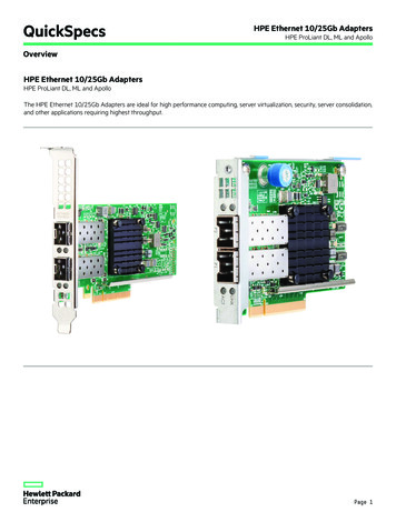
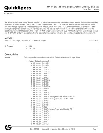
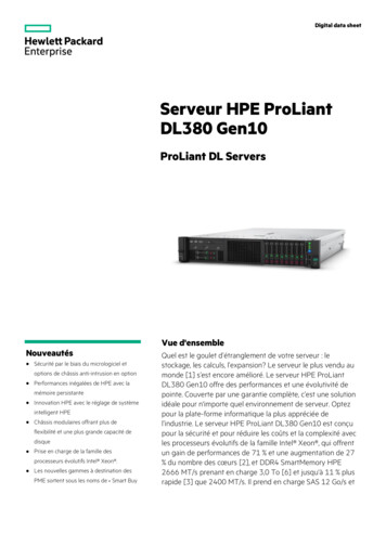
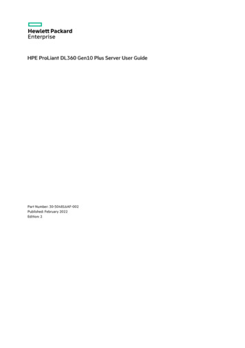
Front panel components8SFFItemDescription1Serial number/iLO information pull tab2Display port (optional) 13Optical drive (optional) 14USB 2.0 port (optional) 15iLO Service Port 26USB 3.0 port7Drive bays1 Optional 2SFF drive bays2 The operating systemdoes not recognize this port as a USB port.4LFFItemDescription1Optical drive blank (optional)2Serial number/iLO information pull tab3Display port (optional)4USB 2.0 port (optional)5Systems Insight Display (optional)6USB 3.0 port7Drive baysFront panel components9
Front panel LEDs and buttons8 SFFItemDescriptionStatus1UID button/LED 1Solid blue ActivatedFlashing blue:1 Hz Remote management or firmwareupgrade in progress4 Hz iLO manual reboot sequence initiated8 Hz iLO manual reboot sequence in progressOff Deactivated2Power On/Standby buttonand system power LED 1Solid green System onFlashing green Performing power on sequenceSolid amber System in standbyOff No power present3Health LED 12Solid green NormalFlashing green iLO is rebooting.Flashing amber System degradedFlashing red System critical4NIC status LED 13Solid green Link to networkFlashing green Network activeOff No network activity123When all four LEDs described in this table flash simultaneously, a power fault has occurred.Facility power is not present, power cord is not attached, no power supplies are installed, power supply failure has occurred, or thepower button cable is disconnected.If the health LED indicates a degraded or critical state, review the system IML or use iLO to review the system health status.4LFFFront panel LEDs and buttons10
ItemDescriptionStatus1UID button/LED 1Solid blue Activated.Flashing blue:1 Hz Remote management or firmwareupgrade in progress.4 Hz iLO manual reboot sequence initiated.8 Hz iLO manual reboot sequence in progress.Off Deactivated.2NIC status LED 1Solid green Link to network.Flashing green Network active.Off No network activity.3Health LED 1Solid green Normal.Flashing green iLO is rebooting.Flashing amber System degraded.Flashing red System critical.4Power On/Standby buttonand system power LED 12Solid green System on.Flashing green Performing power on sequence.Solid amber System in standby.Off No power present.1233When all four LEDs described in this table flash simultaneously, a power fault has occurred.To identify components in a degraded or critical state, see the Systems Insight Display LEDs, check iLO/BIOS logs, and reference theserver troubleshooting guide.Facility power is not present, power cord is not attached, no power supplies are installed, power supply failure has occurred, or thepower button cable is disconnected.Front panel LEDs and buttons11
UID button functionalityThe UID button can be used to display the Server Health Summary when the server will not power on. For more information, see thelatest HPE iLO 5 User Guide on the Hewlett Packard Enterprise website .UID button functionality12
Front panel LED power fault codesThe following table provides a list of power fault codes, and the subsystems that are affected. Not all power faults are used by allservers.SubsystemLED behaviorSystem board1 flashProcessor2 flashesMemory3 flashesRiser board PCIe slots4 flashesOCP adapter5 flashesStorage controller6 flashesSystem board PCIe slots7 flashesPower backplane8 flashesStorage backplane9 flashesPower supply10 flashesPCIe expansion cards installed in riser board11 flashesChassis12 flashesGPU card13 flashesFront panel LED power fault codes13
Systems Insight Display LEDsThe Systems Insight Display LEDs represent the system board layout. The display enables diagnosis with the access panel installed.DescriptionStatusProcessor LEDsOff NormalAmber Failed processorDIMM LEDsOff NormalAmber Failed DIMM or configuration issueFan LEDsOff NormalAmber Failed fan or missing fanNIC LEDs 1Off No link to networkSolid green Network linkFlashing green Network link with activityIf power is off, the front panel LED is not active. For status, see Rear panel LEDs.Power supply LEDs Off NormalSolid amber Power subsystem degraded, power supply failure, or input power lost.PCI riser LEDOff NormalAmber Incorrectly installed PCI riser cageOver temp LEDOff NormalAmber High system temperature detectedPower cap LEDOff System is in standby, or no cap is set.Solid green Power cap appliedSystems Insight Display LEDs14
DescriptionStatusAmp Status LEDOff AMP modes disabledSolid green AMP mode enabledSolid amber FailoverFlashing amber Invalid configuration1Embedded NIC ports are not equipped on the server. NIC LEDs on the Systems Insight Display will flash based on the networkadapter port activity. In the case of a dual-port adapters, only NIC LED 1 and 2 will illuminate to correspond with the activity of therespective network ports.When the health LED on the front panel illuminates either amber or red, the server is experiencing a health event. For more informationon the combination of these LEDs, see Systems Insight Display combined LED descriptions ).Systems Insight Display LEDs15
Systems Insight Display combined LED descriptionsThe combined illumination of the following LEDs indicates a system condition:Systems Insight Display LEDsSystem power LEDHealth LEDSystems Insight DisplayLED and colorHealthLEDSystempower LEDStatusProcessor (amber)RedAmberOne or more of the followingconditions might exist:Processor in socket X has failed.Processor X is not installed inthe socket.Processor X is unsupported.ROM detects a failed processorduring POST.Processor (amber)AmberGreenProcessor in socket X is in a prefailure condition.DIMM (amber)RedGreenOne or more DIMMs have failed.DIMM (amber)AmberGreenDIMM in slot X is in a pre-failurecondition.Over temp (amber)AmberGreenThe Health Driver has detected acautionary temperature level.Over temp (amber)RedAmberThe server has detected a hardwarecritical temperature level.PCI riser (amber)RedGreenThe PCI riser cage is not seatedproperly.Fan (amber)AmberGreenOne fan has failed or has beenremoved.Fan (amber)RedGreenTwo or more fans have failed orbeen removed.Power supply (amber)RedAmberOne or more of the followingconditions might exist:Only one power supply isinstalled and that power supplyis in standby.Power supply fault.System board fault.Power supply (amber)AmberGreenOne or more of the followingconditions might exist:Redundant power supply isinstalled and only one powersupply is functional.AC power cord is not pluggedinto redundant power supply.Redundant power supply fault.Power supply mismatch atPOST or power supplymismatch through hot-plugaddition.Power cap (off)—AmberStandby.Systems Insight Display combined LED descriptions16
Systems Insight DisplayLED and colorHealthLEDSystempower LEDStatusPower cap (green)—FlashinggreenWaiting for power.Power cap (green)—GreenPower is available.Power cap (flashingamber)—AmberPower is not available.IMPORTANT: If more than one DIMM slot LED is illuminated, further troubleshooting is required. Test each bank ofDIMMs by removing all other DIMMs. Isolate the failed DIMM by replacing each DIMM in a bank with a known workingDIMM.Systems Insight Display combined LED descriptions17
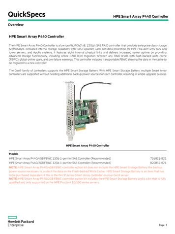
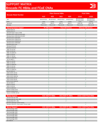
Rear panel componentsItemDescription1Slot 1 PCIe42Slot 2 PCIe43Slot 3 PCIe4 (optional - requires second processor)4Power supply 2 (PS2)5Power supply 1 (PS1)6Video (VGA) port7OCP 3.0 adapter (if equipped)8Serial port (optional)9USB 3.0 ports10iLO Management PortRear panel components18
Rear panel LEDsItemDescriptionStatus1iLO 5/standardNIC link LEDSolid green Link exists.iLO 5/standardNIC activity LEDSolid green Activity exists.2Off No link exists.Flashing green Activity exists.Off No activity exists.3UID LEDSolid blue Identification isactivated.Flashing blue System is beingmanaged remotely.Off Identification is deactivated.4Power supply 2LEDSolid green NormalOff One or more of the followingconditions exists:AC power unavailablePower supply failedPower supply in standby modePower supply exceeded currentlimit.5Power supply 1LEDSolid green NormalOff One or more of the followingconditions exists:AC power unavailablePower supply failedPower supply in standby modePower supply exceeded currentlimit.Rear panel LEDs19
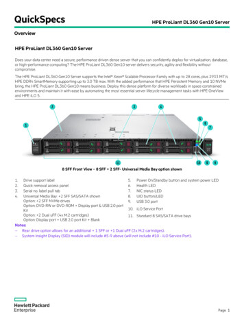
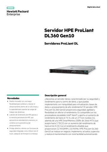
System board componentsItemDescription1x8 Slimline connector2TPM connector3System maintenance switch4Front display port/USB 2.0 connector5Primary (processor 1) PCIe riser connector6x4 SATA port 27x4 SATA port 18x2 SATA port 39Front power/USB 3.0 connector10SATA optical port 411x8 NVMe port 2A12x8 NVMe port 1A13Energy pack connector14x8 NVMe port 2B15x8 NVMe port 1BSystem board components20
ItemDescription16Dual internal USB 3.0 connector17Drive backplane power connector18Chassis Intrusion Detection connector19Secondary (processor 2) PCIe riser connector20Type-a storage controller slot21System battery22Serial port connector23OCP 3.0 adapter baySystem board components21
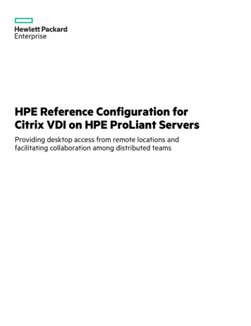
Heatsink and socket componentsItemDescription1Heatsink nuts2Alignment screws3Latch tabs4Heatsink latchesHeatsink and socket components22
System maintenance switch descriptionsPositionDefaultFunctionS1 1OffOff iLO security is enabled.On iLO security is disabled.S2OffReservedS3OffReservedS4OffReservedS5 1OffOff Power-on password is enabled.On Power-on password is disabled.S6 1 , 2 , 3OffOff No functionOn Restore default manufacturing S10—ReservedS11—ReservedS12—ReservedTo access the redundant ROM, set S1, S5, and S6 to On.When the system maintenance switch position 6 is set to the On position, the system is prepared to restore all configuration settingsto their manufacturing defaults.When the system maintenance switch position 6 is set to the On position and Secure Boot is enabled, some configurations cannot berestored.For more information, see Secure Boot.System maintenance switch descriptions23
DIMM slot locationsDIMM slots are numbered sequentially (1 through 16) for each processor.DIMM slot locations24
DIMM label identificationTo determine DIMM characteristics, see the label attached to the DIMM. The information in this section helps you to use the label tolocate specific information about the DIMM.ItemDescriptionExample1Capacity8 GB16 GB32 GB64 GB128 GB256 GB2Rank1R Single rank2R Dual rank4R Quad rank8R Octal rank3Data width on DRAMx4 4-bitx8 8-bit4Memory generationPC4 DDR45Maximum memory speed3200 MT/s6CAS latencyAA CAS 22-22-22AA CAS 26-22-22 (for 3DS LRDIMM)7DIMM typeR RDIMM (registered)L LRDIMM (load reduced)For more information about product features, specifications, options, configurations, and compatibility, see the HPE DDR4SmartMemory QuickSpecs on the Hewlett Packard Enterprise website MM label identification25
Intel Optane persistent memory 200 series for HPE label identificationItemDescriptionExample1Work Order NumberXXXXXXX2Work Order Number BarcodeXXXXXXX3Capacity128 GB256 GB512 GB4Unique ID number8089-A2-1802-1234567A5Serial Number and PartNumber BarcodeS8089A218040000168APNMAXXXXXXXXXXX6Product NameIntel Optane persistent memory7Part Number1234567A8Serial Number Barcode8089-A2-1802-1234567A9PBA NumberXXXXXX-XXXFor more information about product features, specifications, options, configurations, and compatibility, see the product QuickSpecs onthe Hewlett Packard Enterprise website ntel Optane persistent memory 200 series for HPE label identification26
Drive numbering8SFF and 8SFF 2SFF device bay numberingItemDescription1Box 1, bays 1-82Box 2, bays 1 and 24 LFF device bay numberingItemDescription1Box 1, bays 1-4Drive numbering27
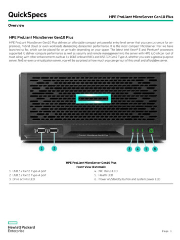
HPE Basic Drive LED definitionsLFF low-profile drive carrierThe LFF low-profile drive carrier supports hot-plug SAS and SATA drives.SFF basic drive carrierThe SFF basic drive carrier supports hot-plug SAS, SATA, and NVMe drives.ItemLEDStatusDefinition1Fault/LocateSolid amberThis drive has failed, is unsupported, or is invalid.Solid blueThe drive is operating normally and being identified bya management application.Flashing amber/blue (1 flashper second)The drive has failed, or a predictive failure alert hasbeen received for this drive. The drive has also beenidentified by a management application.Flashing amber (1 flash persecond)A predictive failure alert has been received for thisdrive. Replace the drive as soon as possible.Solid greenThe drive is online and has no activity.Flashing green (1 flash persecond)The drive is doing one of the following:Rebuilding or performing a RAID2Online/ActivityPerforming a stripe size migrationPerforming a capacity expansionPerforming a logical drive extensionErasingSpare part activationFlashing green (4 flashes persecond)The drive is operation normally and has activity.OffThe drive is not configured by a RAID controller or is aspare drive.HPE Basic Drive LED definitions28
HPE Basic Drive LED definitions29
Hot-plug fansCAUTION: To avoid damage to server components, fan blanks must be installed in fan bays 1 and 2 in a singleprocessor configuration.CAUTION: To avoid damage to the equipment, do not operate the server for extended periods of time if the server doesnot have the optimal number of fans installed. Although the server might boot, Hewlett Packard Enterprise does notrecommend operating the server without the required fans installed and operating.The valid fan configurations are listed in the following tables.One-processor configurationFan bay 1Fan bay 2Fan bay 3Fan bay 4Fan bay 5Fan bay 6Fan bay 7Fan blankFan blankFanFanFanFanFanTwo-processor configurationFan bay 1Fan bay 2Fan bay 3Fan bay 4Fan bay 5Fan bay 6Fan bay 7FanFanFanFanFanFanFanThe loss of a single fan rotor (one standard fan) causes loss of redundancy. The loss of two fan rotors (two standard fans or one highperformance fan) causes the server to initiate a shutdown.The high performance fans are required for some drive configurations. They are also required for ASHRAE-compliant configurations.For more information on ASHRAE-compliant configurations, see the Hewlett Packard Enterprise websitehttps://www.hpe.com/servers/ASHRAE.The server supports variable fan speeds. The fans operate at minimum speed until a temperature change requires a fan speed increaseto cool the server. The server shuts down during the following temperature-related scenarios:At POST and in the OS, iLO performs an orderly shutdown if a cautionary temperature level is detected. If the server hardwaredetects a critical temperature level before an orderly shutdown occurs, the server performs an immediate shutdown.When the Thermal Shutdown feature is disabled in the BIOS/Platform Configuration (RBSU), iLO does not perform an orderlyshutdown when a cautionary temperature level is detected. Disabling this feature does not disable the server hardware fromperforming an immediate shutdown when a critical temperature level is detected.CAUTION: A thermal event can damage server components when the Thermal Shutdown feature is disabled in theHot-plug fans30
BIOS/Platform Configuration (RBSU).Hot-plug fans31
DSC-25 2-port SFP28 card ports and LEDsPortsTable 1: PortsItemPortDescription1Management port1GbE RJ452Network interface port10/25G SFP based3Network interface port10/25G SFP basedLEDsThe HPE for Pensando DSP DSC-25 2p SFP28 card is a dual-port, single-slot, half-height, half-length (HHHL) SFP28 network adapter.It has LEDs for Link (L) and Activity (A) for each port. A half-height bracket is shown in the following illustration with SFP28 ports andLEDs.Table 2: LED indicatorsItemLED1Management Port Activity OffLEDFlashingNo activityManagement Port LinkLEDOffA link has not been establishedSolid greenValid Ethernet linkOffA link has not been establishedSolid greenValid Ethernet linkFlashing greenPassing traffic; flashing frequency indicates trafficintensitySolid amberLink fault23SFP Port 1 Link/ActivityLEDStatusDescriptionPassing traffic; flashing frequency indicates trafficintensityDSC-25 2-port SFP28 card ports and LEDs32
ItemLEDStatusDescription4SFP Port 2 Link/ActivityLEDOffA link has not been establishedSolid greenValid Ethernet linkFlashing greenPassing traffic; flashing frequency indicates trafficintensitySolid amberLink faultOffSystem is not poweredSolid amberPower is up, software has not booted yetSolid greenSystem is up and fully operational5System status LEDDSC-25 2-port SFP28 card ports and LEDs33
HPE NS204i-p NVMe OS Boot Device componentsItemDescription1Drive bay 12Drive bay 23Thermal interface pad with removable liner4M.2 drive retaining latchesHPE NS204i-p NVMe OS Boot Device components34
HPE NS204i-p NVMe OS Boot Device LED definitionsItemDescription Fault LED status1Bay 1 LED2Bay 2 LEDOff: NormalFlashing 1Hz: Drive predictive failureAmber: Drive failureHPE NS204i-p NVMe OS Boot Device LED definitions35
OperationsOperations36
Power up the serverTo power up the server, use one of the following methods:Press the Power On/Standby button.Use the virtual power button through iLO.Power up the server37
Power down the serverBefore powering down the server for any upgrade or maintenance procedures, perform a backup of critical server data and programs.IMPORTANT:When the server is in standby mode, auxiliary power is still being provided to the system.To power down the server, use one of the following methods:Press and release the Power On/Standby button.This method initiates a controlled shutdown of applications and the OS before the server enters standby mode.Press and hold the Power On/Standby button for more than 4 seconds to force the server to enter standby mode.This method forces the server to enter standby mode without properly exiting applications and the OS. If an application stopsresponding, you can use this method to force a shutdown.Use a virtual power button selection through iLO .This method initiates a controlled remote shutdown of applications and the OS before the server enters standby mode.Before proceeding, verify that the server is in standby mode by observing that the system power LED is amber.Power down the server38
Extend the server from the rackNOTE:If the cable management arm option is installed, you can extend the server without powering down the server ordisconnecting peripheral cables and power cords. These steps are only necessary with the standard cable managementsolution.Procedure1. Power down the server.2. Disconnect all peripheral cables and power cords.3. Loosen the front panel thumbscrews.4. Extend the server on the rack rails until the server rail-release latches engage.WARNING:To reduce the risk of personal injury or equipment damage, be sure that the rack isadequately stabilized before extending a component from the rack.WARNING:To reduce the risk of personal injury, be careful when pressing the server rail-release latchesand sliding the server into the rack. The sliding rails could pinch your fingers.5. After the installation or maintenance procedure, slide the server into the rack:a. Slide the server fully into the rack.b. Secure the server by tightening the thumbscrews.6. Connect the peripheral cables and power cords.Extend the server from the rack39
Remove the server from the rackTo remove the server from a Hewlett Packard Enterprise, Compaq-branded, Telco, or third-party rack:Procedure1. Power down the server.2. Extend the server from the rack .3. Disconnect the cabling and remove the server from the rack. For more information, see the documentation that ships with the rackmounting option.4. Place the server on a sturdy, level surface.Remove the server from the rack40
Remove the access panelWARNING: To reduce the risk of personal injury from hot surface
2.1 Power up the server 2.2 Power down the server 2.3 Extend the server from the rack 2.4 Remove the server from the rack 2.5 Remove the access panel 2.6 Install the access panel 2.7 Remove the hot-plug fan 2.8 Remove the primary PCI riser cage 2.9 Install the primary PCI riser cage 2.10 Remove the secondary PCI riser cage