Transcription
Industrial Router Ultra SeriesUR75Quick Start Guide1
Safety PrecautionsMilesight will not shoulder responsibility for any loss or damage resulting from not following theinstructions of this operating guide. The device must not be modified in any way. Do not place the device close to objects with naked flames. Do not place the device where the temperature is below/above the operating range. Do not power on the device or connect it to other electrical device when installing. Check lightning and water protection when used outdoors. Do not connect or power the equipment using cables that have been damaged.Related DocumentsThis Start Guide only explains the installation of Milesight UR75 router. For more functionality andadvanced settings, please refer to the relevant documents as below.DocumentDescriptionUR75 DatasheetDatasheet for UR75 industrial cellular router.UR75 User GuideUsers could refer to the guide for instruction on how to log in the web GUI, andhow to configure all the settings.The related documents are available on Milesight website: https://www.milesight-iot.comDeclaration of ConformityUR75 are in conformity with the essential requirements and other relevant provisions of the CE, FCC, andRoHS. 2011-2022 Xiamen Milesight IoT Co., Ltd.All rights reserved.All information in this guide is protected by copyright law. Whereby, no organization or individual shallcopy or reproduce the whole or part of this user guide by any means without written authorization fromXiamen Milesight IoT Co., Ltd.For assistance, please contactMilesight technical support:Email: iot.support@milesight.comTel: 86-592-5085280Fax: 86-592-5023065Address: Building C09, Software Park III, Xiamen361024, China2
Revision HistoryDateDoc VersionDescriptionAug. 4, 2020V 1.0Initial versionNov. 20, 2020Dec. 1, 2021V 2.0V 2.1Layout replaceUpdate cellular picturesJune 8, 2022V 2.21. Wall mounting bracket customizable2. Web GUI logo update3
Contents1. Packing List . 52. Hardware Introduction .62.1 Overview .62.2 Dimensions . 72.3 Serial & IO & Power Pinouts .72.4 LED Indicators . 82.5 Reset Button . 82.6 Ethernet Port Indicator .93. Hardware Installation . 103.1 SIM Card Installation .103.2 Antenna Installation . 103.3 Router Installation . 103.3.1 DIN Rail Mounting .113.3.2 Wall Mounting .113.4 Protective Grounding Installation . 114. Log in the Web GUI of Router . 124.1 Wireless Access . 124.2 Wired Access .135. Network Configuration . 165.1 Ethernet WAN Configuration . 165.2 Cellular Connection Configuration .165.3 Wi-Fi Configuration .184
1. Packing ListBefore you begin to install the UR75 router, please check the package contents to verify that you havereceived the items below.1 UR751 Ethernet Cable1 Power Adapter1 8-Pin PluggableTerminal1 DIN Rail Kit1 Quick Start Guide1 Warranty Card1 Wall MountingBracket(Customizable)UR75-5G Antennas:4 Stubby CellularAntennas2 Stubby Wi-FiAntennasAntenna MagneticMount(Optional)UR75-4G Antennas:2 Magnetic CellularAntennas2 Stubby Wi-FiAntennas1 GPS Antenna2 Stubby CellularAntennas (Optional)If any of the above items is missing or damaged, please contact your sales representative.5
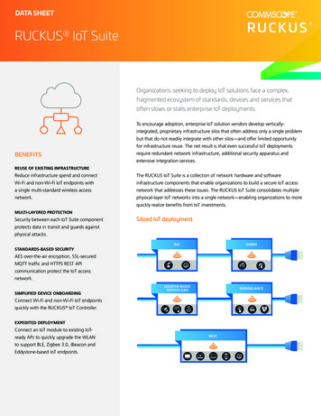
2. Hardware Introduction2.1 OverviewA. Front Panel of UR75-5G123B. Front Panel of UR75-4G1LED Indicator AreaPOWER: Power IndicatorSYSTEM: Status IndicatorWi-Fi: Wi-Fi IndicatorVPN: VPN IndicatorSIM : SIM Status Indicator: Signal Strength IndicatorEthernet Ports & IndicatorsCellular Antenna Connectors(Connector 4 is for both GPS and cellular)LED Indicator AreaPOWER: Power IndicatorSYSTEM: Status IndicatorWi-Fi: Wi-Fi IndicatorVPN: VPN IndicatorSIM : SIM Status Indicator: Signal Strength Indicator23Ethernet Ports & IndicatorsAntenna ConnectorsMAIN: Main Cellular Antenna ConnectorAUX: Auxiliary Cellular Antenna ConnectorGPS: GPS Antenna ConnectorC. Left Side Panel456789Wi-Fi Antenna Connector 1Wi-Fi Antenna Connector 2USB Port (Reserved)Power ConnectorSerial Port & I/O PortsGrounding Stud6
D. Right Side Panel10SIM and Reset Button Holder2.2 Dimensions (mm)2.3 Serial & IO & Power ital Input2GND---GND---Ground3---B------Data -4TXD---------Transmit Data5---------COMCommon Ground6---------OUTDigital Output7---A------Data 8RXD---------Receive DataNote: For -RS485 model, RXD--- A, TXD--- B.PINDescriptionWire Color9PositiveRed10NegativeBlack7
2.4 LED IndicatorsLEDIndicationPOWERPower StatusSYSTEMVPNWi-FiSystem StatusVPN StatusWi-Fi StatusStatusDescriptionOffThe power is switched offOnThe power is switched onGreen LightStatic: Start-upBlinking slowly: the system is running properlyRed LightThe system goes wrongOffVPN is disconnectedGreen LightVPN is connectedOffWi-Fi is disabledGreen LightStatic: Wi-Fi is enabledBlinking slowly: sending or receiving data via Wi-FiSIM1 or SIM2 is registering or fails to register (or thereare no SIM cards inserted)OffBlinking slowly: SIM1 (as primary SIM) has beenregistered and is ready for dial-upGreen LightSIMBlinking rapidly: SIM1(as primary SIM) has beenregistered and is dialing up nowStatic: SIM1 (as primary SIM) has been registered anddialed up successfullySIM Card StatusBlinking slowly: SIM2 (as primary SIM) has beenregistered and is ready for dial-upOrangeLightBlinking rapidly: SIM2 (as primary SIM) has beenregistered and is dialing up nowStatic: SIM2 (as primary SIM) has been registered anddialed up successfullyOffSignalStrengthSignal 1/2/3No signalStatic/Off/Off: weak signals with 1-10 ASU (pleasecheck if the antenna is installed correctly, or move theantenna to a suitable location to get better signal)Green LightStatic/Static/Off: normal signals with 11-20 ASU(average signal strength)Static/Static/Static: strong signals with 21-31 ASU(signal is good)2.5 Reset ButtonReset button is under the SIM slots.FunctionResetDescriptionSYSTEM LEDActionBlinkingPress and hold the reset button for more than 5 seconds.8
Static Green Rapidly BlinkingRelease the button and wait.Off BlinkingThe router is now reset to factory defaults.2.6 Ethernet Port IndicatorIndicatorLink Indicator itting dataOffDisconnected9
3. Hardware InstallationEnvironmental Requirements- Power Input: 9-48 VDC (48 VDC is needed for PoE output)- Power Consumption: 7.9W (In Non-PoE mode)- Operating Temperature: -40 C to 70 C (-40 F -158 F)- Relative Humidity: 0% to 95% (non-condensing) at 25 C/77 F3.1 SIM Card InstallationUR75 do not support hot-plug. Please cut off the power before insert or take off cards.A. Unscrew the holder of the SIM card.B. Insert the SIM card(s) into the device following the triangle location of SIM card(s).C. Put SIM card into the slot and screw it up.3.2 Antenna InstallationRotate the antenna into the antenna connector accordingly.The external antenna should be installed vertically always on a site with a good signal.3.3 Router InstallationThe router can be placed on a desktop or mounted to a wall or a DIN rail.10
3.3.1 DIN Rail Mounting (Measured in mm)Use 2 pcs of M3 6 flat head Phillips screws to fix the mount clip to the router, and then hang the deviceto the DIN rail. The width of DIN rail is 3.5cm.Recommended torque for mounting is 1.0 N·m, and the maximum allowed is 1.2 N·m.3.3.2 Wall Mounting (Measured in mm)Use 2 pcs of M3 6 flat head Phillips screws to fix the wall mounting bracket to the router, and then use2 pcs of M3 drywall screws to mount the router associated with the wall plugs on the wall.Recommended torque for mounting is 1.0 N·m, and the maximum allowed is 1.2 N·m.3.4 Protective Grounding InstallationRemove the grounding nut, then connect the grounding ring of the cabinet’s grounding wire onto thegrounding stud and screw up the grounding nut.The router must be grounded when deployed. According to operating environment, the groundwire should be connected with grounding stud of router.11
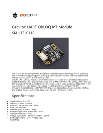
4. Log in the Web GUI of RouterUR75 provides web-based configuration interface for management. If this is the first time you configurethe device, please use the default settings below:IP Address: 192.168.1.1Username: adminPassword: password4.1 Wireless AccessA. Enable Wireless Network Connection on your computer and search for access point “Router ******”to connect it.B. Open a Web browser on your PC (Chrome is recommended) and type in the IP address 192.168.1.1 toaccess the web GUI.C. Enter the username and password, and click “Login”.If you enter the username or password incorrectly more than 5 times, the login page will belocked for 10 minutes.D. When you login with the default username and password, you will be asked to modify the password.It’s suggested that you change the password for the sake of security. Click "Cancel" button if you want tomodify it later.12
E. After you login the Web GUI, you can view system information and perform configuration on thedevice.4.2 Wired AccessConnect PC to LAN port of UR75 router directly. The following steps are based on Windows 10 operatingsystem for your reference.A. Go to “Control Panel” “Network and Internet” “Network and Sharing Center”, then click “Ethernet”(May have different names).B. Go to “Properties” “Internet Protocol Version 4(TCP/IPv4) ”, select “Obtain an IP addressautomatically” or “Use the following IP address”, then assign a static IP manually within the same subnetof the device.13
C. Open a Web browser on your PC (Chrome is recommended), type in the IP address 192.168.1.1, andpress Enter on your keyboard.D. Enter the username, password, and click "Login".If you enter the username or password incorrectly more than 5 times, the login page will belocked for 10 minutes.E. When you login with the default username and password, you will be asked to modify the password.It’s suggested that you change the password for the sake of security. Click "Cancel" button if you want tomodify it later.14
F. After you login the Web GUI, you can view system information and perform configuration on thedevice.15
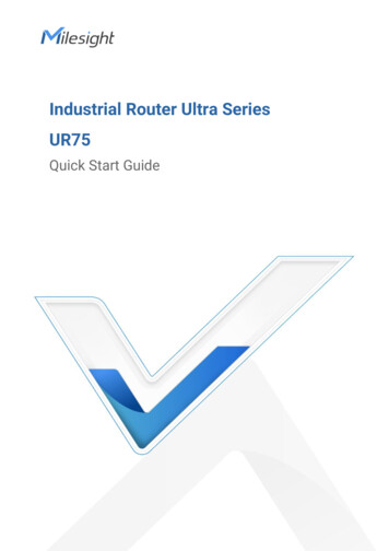
5. Network ConfigurationThis chapter explains how to connect UR75 to network via WAN connection, Wi-Fi or cellular.5.1 Ethernet WAN ConfigurationA. Go to “Network” “Interface” “WAN” to select connection type and configure WAN parameters,click “Save & Apply” button to make the changes take effect.B. Connect WAN port to another network devices like modem.C. Go to “Network” “Interface” “Link Failover” to rise the WAN priority to 1.D. Open your preferred browser on PC, then type any available web address into address bar and see if itis able to visit Internet via UR75 router.5.2 Cellular Connection ConfigurationTake inserting SIM card into SIM1 slot as an example; please refer to the following detailed operations.A. Go to “Network” “Interface” “Cellular” “Cellular Setting” to configure APN, PIN code or other16
cellular info, click “Save” and “Apply” to save the configuration.B. Go to “Network” “Interface” “Link Failover” to enable SIM1 and rise link priority of SIM1.C. Clickto configure ICMP ping detection information.17
D. Click “Status” “Cellular” to view the status of the cellular connection. If it shows “Connected”, itmeans SIM1 has dialed up successfully. On the other hand, you can check the status of SIM indicator. Ifit keeps on light statically, it means SIM1 has dialed up successfully.E. Open your preferred browser on PC, then type any available web address into address bar and see if itis able to visit Internet via UR75 router.5.3 Wi-Fi ConfigurationA. Go to “Network” “Interface” “WLAN” and select “Client” mode.B. Click “Scan” to search for Wi-Fi access point. Select the available one and click “Join Network”.C. Type the key of Wi-Fi.18
D. Go to “Network” “Interface” “Link Failover” to enable WLAN.E. Go to “Status” ”WLAN” to check Wi-Fi status. If it shows “Connected”, it means the device connectsto Wi-Fi successfully.[END]19
VPN VPNStatus Off VPNisdisconnected GreenLight VPNisconnected Wi-Fi Wi-FiStatus Off Wi-Fiisdisabled GreenLight Static:Wi-Fiisenabled Blinkingslowly:sendingorreceivingdataviaWi-Fi SIM SIMCardStatus Off SIM1 or SIM2 is registering or fails to register (or there arenoSIMcardsinserted) GreenLight Blinking slowly: SIM1 (as primary SIM) has been