Transcription
Page 1TD-700LaboratoryFluorometerOperatingManualDated: 5/8/2002Version 2.0Part Number 7000-998TD-700 Laboratory Fluorometer Operating Manual
Page 1TD-700LaboratoryFluorometerOperatingManualDated: 5/8/2002Version 2.0Part Number 7000-998TD-700 Laboratory Fluorometer Operating Manual
Page 2TD-700 Laboratory FluorometerOperating ManualTable of ContentsI.IntroductionA. DescriptionB. Inspection and SetupC. General PrecautionsD. Definition of Symbols5II.Hardware OverviewA. TD-700 Quick View DiagramB. TD-700 Controls7III.Optical Filter Installation and Removal9IV.Lamp Installation and RemovalA. The Mercury Vapor LampB. The Quartz Halogen Lamp11V.Instrument Parameters (Firmware)A. Power-up ScreenB. HOME ScreenC. Setup/Calibration ScreenD. Setup ScreensE. Calibration ScreensF. Firmware Flow Chart13VI.Calibration OverviewA. Why Calibrate?B. When to CalibrateC. TD-700 Calibration Options18VII.Calibration: Simple Mode20VIII. Calibration: Multi-Optional Mode - Raw Fluorescence22IX.Calibration: Multi-Optional Mode - Direct ConcentrationA. To CalibrateB. How Sample Concentrations Will Be CalculatedC. To View the Last CalibrationD. To Abort the Calibration24X.Reading SamplesA. Reading SamplesB. Resetting Blank to ZeroC. Data Stream28TD-700 Laboratory Fluorometer Operating Manual
Page 3APPENDICESAPPENDIX 1 - Before Calibration or Reading SamplesA. Materials NeededB. When Handling SamplesC. Linear Range and "Quenching"Figure 1: Linearity, Calibration Curve, and QuenchingD. Temperature ConsiderationsE. Positioning SamplesF. Data Quality30APPENDIX 2 - The Calibration Printout33A. Printout Capability with a Printer or ComputerB. Sample Reading with a Printer or ComputerC. Calibration Printout Using the Direct Concentration CalibrationProcedureD. Calibration Printout in the Multi-Optional Raw Fluorescence CalibrationE. Calibration Printout Using the Simple ModeAPPENDIX 3 - Alarms & DiagnosticsA. Alarm ScreenB. Diagnostic Screens36APPENDIX 4 - Troubleshooting38APPENDIX 5 - Data Collection39APPENDIX 6 - Sample and Cuvette AdaptersA. Installing and Removing Sample AdaptersB. Minicell Adapter40APPENDIX 7 - Glossary42APPENDIX 8 - Error Messages and NotesA. Invalid InputB. Error1C. Notes 1 and 2D. Error3E. Error4F. Error5G. Error6H. Home Screen Displays: OVER, or Negative (-) NumbersI. Blank Level Error45APPENDIX 9 - Maintenance, Warranty, & ServiceA. MaintenanceB. WarrantyC. Obtaining Service47APPENDIX 10 - Specifications & Features49APPENDIX 11 - Principles of Fluorescence51APPENDIX 12 - Instructions for Using the Solid Standard53TD-700 Laboratory Fluorometer Operating Manual
Page 4NOTESTD-700 Laboratory Fluorometer Operating Manual
Page 5I.IntroductionA.DescriptionThe TD-700 Fluorometer is a compact, laboratory fluorometer designed fordiscrete sample measurement of various fluorescent materials, includingchlorophyll, rhodamine, fluorescein, histamine, vitamins, and other fluorescent compounds. When properly calibrated, TD-700 will electronically setthe optimal sensitivity and range for your samples, and will readout theactual concentration of the compound when in the Direct Concentrationmode. The TD-700 can be set up to detect the specific compound youwant to measure simply by changing the lamp and optical filters.B.Inspection and SetupUpon receiving your fluorometer, please inspect it carefully and make sureall accessories are present (refer to the packing list shipped with theinstrument).TD-700 Top ViewTo get started (Refer to the Quick View Diagram, page 7):1. Locate the instrument on a flat surface with the back of the instrumentwell ventilated (at least three inches from a wall).2. Open the sample chamber lid located on the top of the unit.3. Remove the Filter Cylinder by grasping the inside rim of the cylinderand pulling up.4. Install the correct optical filters for your application. See Section III fordetails.5. Check that the correct lamp is installed for your primary application.See Section IV for details.6. Check to see that the sample adaptor is the correct one for yourneeds. Refer to Appendix 6 for a detailed explanation of TD-700Sample Adaptors.TD-700 Front ViewFilter CylinderAssembly7. Reinsert the Filter Cylinder, lining up either the A, B, C or D application indicators on the cylinder with the silver alignment mark on theinside rim of the sample chamber. Replace the sample adaptor makingsure that the adaptor is properly seated in the filter cylinder, and closethe sample chamber lid.8. Plug in the unit. Be sure to use only the Turner Designs powersupply provided with your instrument. It is critical to use the powersupply provided by Turner Designs to meet EMI requirements.9. Turn on the power switch (rear of unit) and allow the unit to warm up forthe countdown period (600 seconds; 10 minutes).NOTE: For optimal instrument stability, leave the instrument turned on.TD-700 Side ViewTD-700 Laboratory Fluorometer Operating Manual
Page 6C.General PrecautionsDo not leave the instrument reading "OVER" for an extended period of time(several minutes). Instrument instability can result.If you are using the quartz halogen lamp, do not touch the bulb. It may behot. Also, oils from your hand will affect the lamp's transmission.When using solvents or other chemicals, please refer to the appropriateMaterial Safety Data Sheet (MSDS) for information regarding handling.When using potentially hazardous chemicals, please use closed-cap testtubes whenever possible and limit exposure. If closed cap test tubes arenot available, Parafilm should be used to prevent the spillage of volatile orother potentially hazardous chemicals.Chemicals should be used in accordance with local regulations and usedin a well ventilated area.Do not defeat the lamp interlock switch. UV light may cause permanentdamage to your eyes.D.Definition of SymbolsDirect Current. 12 volts D.C.Easily touched higher temperature parts.Caution. Read instruction manual and refer to warning text.TD-700 Laboratory Fluorometer Operating Manual
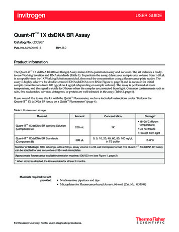
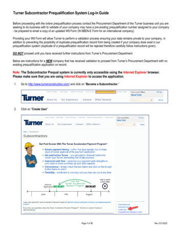
Page 7II.Hardware OverviewA.TD-700 Quick View DiagramAlignment MarkAlignment MarkFilter CylinderSample AdapterSilver Alignment MarkSample ChamberDisplayKeypadTD-700 Laboratory FluorometerTD-700 Filter Cylinder and13 mm SampleAdapter25 mm Round SampleAdapter10 mm Square CuvetteAdapterTD-700 Laboratory Fluorometer Operating Manual
Page 83B.TD-700 Controls1. Display — Shows the screens and readout for samples. It is litcontinuously when the unit is operating. Except during calibration, thecontrast of the display can be adjusted on any screen by pressing theup or down arrow keys.12. Keypad — The keypad is used to enter new values and to movethrough the software screens.23. Sample Chamber — Samples are placed inside the chamber forreading. It houses the Filter Cylinder and the cuvette adaptor.4. Filter Cylinder —The Filter Cylinder has openings for various opticalfilter combinations. It can be removed by grasping the inside rim of thecylinder and pulling it straight up.TD-700 Front View5. Sample Adapters — Adapters are available for various test tube orcuvette sizes. The sizes used with the TD-700 are: 25 mm round, 13mm round, 10 mm square, or 100µl minicell.46. Lamp Access Panel — To access the lamp, remove the panel bypulling on the two black quick-release latches on the lamp accesspanel. The lamp provides excitation light at wavelengths specific to thecompound to be measured.7. Power Switch — ON/OFF switch.8. RS-232 Serial Port Connection — RS-232 (DB9 female from the TD700) serial port for connecting to a computer or printer.TD-700 Filter Cylinder Assembly9. Power Plug Socket — The power supply connects into the rear panelof the instrument.510. Drain Plug — The TD-700 is equipped with a non-removable plug(located underneath the instrument) for drainage if there is a spill in thesample compartment.11. Lamp Viewport — The mercury vapor lamp access panel has a lampviewport that allows the user to observe whether the lamp is lit withoutopening the door.6611TD-700 Sample Adapters13 mm, 25 mm, and 10 mm10TD-700 Laboratory Fluorometer Operating ManualTD-700 with Halogen LampRear View88779910TD-700 with Mercury VaporLamp - Rear View
Page 9Filter CylinderAssemblyIII. Optical Filter Installation and RemovalThe TD-700 Fluorometer must have two different optical filters to operatecorrectly: an excitation filter and an emission filter. TD-700 filters are oneinch diameter, round, colored glass or highly-reflective glass. The filters aremounted in the Filter Cylinder using flexible rubber o-rings. The FilterCylinder is accessed through the sample chamber. The Cylinder can holdfour different excitation/emission filter combinations, and is labeled on onerim, “A” and “B”; and labeled on the opposite rim, “C” and “D”. Each ofthese letters identifies a filter application set. Once the filter sets areinstalled properly in the cylinder, changing from one application to anotherrequires a simple repositioning of the cylinder and possibly a lamp change.To remove or install optical filters in the Filter Cylinder:a. Remove any test tubes or cuvettes and sample adaptors from theinstrument. Then, grasp the Filter Cylinder by the rim and pull straightup and out of the unit.b. Locate the filters (excitation and emission filters) for the applicationyou want to run. Filters are marked on their rim with an identificationnumber.TD-700 Side Viewc. The Filter Cylinder has eight openings for four different filter sets. Forexample, the openings for filter set A are marked “A/EX” and “A/EM”;filter set B is marked “B/EX” and “B/EM”. Select the A, B, C, or Dpositions to install the filters.d. Find the openings for the filter set you want to remove. For example, ifyou want to install the filters in position B, then remove any filters fromthe B/EX and B/EM openings. To remove a filter, take out the flexiblerubber o-ring holding the filter in place. Use a tool such as a plasticpen cap or plastic-nosed forceps to do this. Be careful not to scratchthe surface of the filter. Place your hand over the opening and tilt thecylinder so the filter drops out into your hand. Be careful, the filtersare glass and may break if dropped.e. Locate the excitation filter to be installed. Handle the filter on theedges so as to avoid leaving fingerprints on the filter, or wipe off thefilter before installing. If the filter has one side that is “mirrored” orhighly reflective, it should be installed so the mirrored side facesoutward from the cylinder (toward the lamp). Insert it (mirrored sideout, if any) in the opening marked with the set letter/”EX”. Push thefilter in so it rests flush with the back of the opening. Then reinsert theo-ring and press it in until it is flush against the filter.TD-700 Filter Cylinder AssemblyTD-700 Laboratory Fluorometer Operating Manual
Page 10f.Locate the emission filter to be installed. Handle the filter at the edgesso as to avoid leaving fingerprints on the filter, or wipe off the filterbefore installing. If the filter has one side that is “mirrored” or highlyreflective, it should be installed so the mirrored side faces toward theinside of the cylinder (toward the sample). Insert it (mirrored side in, ifany) in the opening marked with the appropriate set letter/”EM”. Pushthe filter in so it rests flush with the back of the opening. Then reinsertthe o-ring and press in with your plastic pen cap until it is flush againstthe filter.g. Position the Filter Cylinder in the sample chamber so that the alignment mark for the filter set you are using is aligned with the silveralignment mark on the inside rim of the sample chamber.TD-700 Laboratory Fluorometer Operating Manual
Page 11IV. Lamp Installation and RemovalThere are two types of lamps available for the TD-700: the Mercury Vaporand the Quartz HalogenA.The Mercury Vapor LampThe low pressure mercury vapor lamp comes in various types dependingon the application of interest. The average life of a mercury vapor lamp is8000 hours. The lamp can be checked without removing the lamp accesspanel by viewing through the lamp view port. If the lamp access panel isremoved, the power to the mercury lamp will be cut off. This safety featurewill prevent the user from being exposed to U.V. light. Do not defeat theinterlock switch. U.V. light may cause permanent damage to youreyes.Quick-releaselatchesCheck the lamp view port if:1. The instrument is not responding, even though the unit is plugged inand the power is on.Lamp View Port2. The readings are very low, unstable, or drifting.TD-700 with Mercury VaporLamp - Rear ViewNote: After replacing a lamp, you must always recalibrate.To replace the mercury vapor lamp:1. Unplug the instrument and remove the lamp access panel by pullingon the two black quick-release latches on the rear panel of the instrument.2. Before replacing a lamp, make sure the current lamp is fully seated inboth the upper and lower lamp sockets. Be cautious when removing the lamp. It may be hot.3. To remove the lamp, grasp it carefully and turn it about 90 degreesuntil the prongs line up with the slots on the lamp sockets. Slide it out.NOTE: To avoid breaking the lamp when replacing it, make sure it isfully seated! At the bottom lamp socket, a metal spring exerts pressure against the lamp; be sure this spring is not preventing properseating before twisting lamp into place.4. To install a new lamp, line up the lamp prongs with the slots on thelamp sockets, push the lamp in and turn it about 90 degrees so it isfirmly seated. Make sure both end caps are properly seated or thelamp will not work!5. Replace the lamp access panel and push in the black quick-releaselatches to snap the panel in place.6. Turn on the power. Check the lamp view port to ensure the lamp is lit.Also make sure the fan is operating. If the fan is not operating, checkthe connector plug.TD-700 Laboratory Fluorometer Operating Manual
Page 12Quick-releaselatchesB.The Quartz Halogen LampThe average halogen lamp life is 2000 hours.Check the lamp if:1. The instrument is not responding, even though the unit is plugged inand the power is on2. The readings are very low, unstable, or drifting.To replace the quartz halogen lamp:TD-700 with Halogen LampRear View1. Turn off the instrument and remove the lamp access panel by pullingon the two black quick-release latches on the rear panel of the instrument.2. Unplug the power jack that connects the lamp panel assembly to theinstrument. The lamp access panel should now pull free of the instrument.3. DO NOT TOUCH THE LAMP BULB with an ungloved hand; thebulb may be hot, and/or the oils from your hand will affect thelamp's transmittance and cause incorrect readings. If the bulb isburned out, grab the bulb with a tissue and pull it out of the assembly.Using the same tissue, insert a new bulb (orientation does not matter).4. Plug the power jack back into the main instrument and replace thelamp access panel. Push in the black quick-release latches to snapthe panel in place.5. Turn on the power. Check to ensure the lamp is lit by viewing itthrough the fan opening. Also make sure the fan is operating. If the fanis not operating, check the connector plug.6. You must recalibrate if you replace the lamp.TD-700 Laboratory Fluorometer Operating Manual
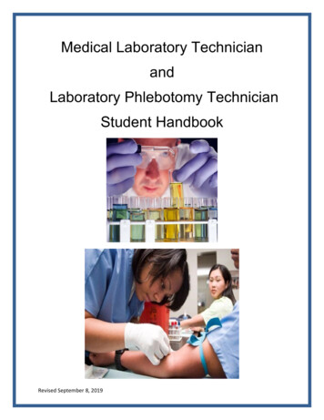
Page 13V.Instrument Parameters (Firmware)Instrument parameters are set through the TD-700 firmware interface.Firmware screens are called up using the keypad. To see how thescreensfit together, see the firmware flowchart on pages 16 & 17. For details aboutalarms and instrument diagnostics, see Appendix 3, Section A, andSection B.A.Power-up ScreenWhen the unit is first turned on, a screen appears showing the title,software version, and a 600-second (10-minute) countdown. Once the 600second countdown expires, the HOME screen will appear. The countdownallows the instrument to warm up adequately before measurements begin.For optimal stability and accuracy, it is recommended that you allow theinstrument to complete the countdown period. For best results, leave theinstrument turned on in your laboratory.TURNER DESIGNST7-1B 10/96 600A. Power-up ScreenIf you wish to bypass the countdown period, press H , ESC , or ENT . From the HOME screen, press 9 to return to the Power-upscreen.B.HOME ScreenAfter the countdown period, the HOME screen is displayed. The HOMEscreen is where samples are read and data is sent to the printer orcomputer. Press H to return to this screen from any screen (exceptduring calibration).XXXppm ENT -Setup & CalB. HOME ScreenFrom the HOME screen, several functions can be accessed.- Press D to send data to a printer or computer.- Press * to Discrete Sample Average (See Section X for details).- Press 0 to Autozero or blank the instrument (See Section X fordetails).- Press 8 for Diagnostic Screens.- Press 7 for Data Stream.C.Setup/Calibration ScreenThe Setup/Calibration screen, accessed from the HOME screen bypressing ENT , is a screen where the user selects either to go to thecalibration sequence or to review or change the setup parameters. Theuser may also press D from this screen to send the current calibrationinformation to a printer or computer.1. Setup2. CalibrationC. Setup/Calibration ScreenTD-700 Laboratory Fluorometer Operating Manual
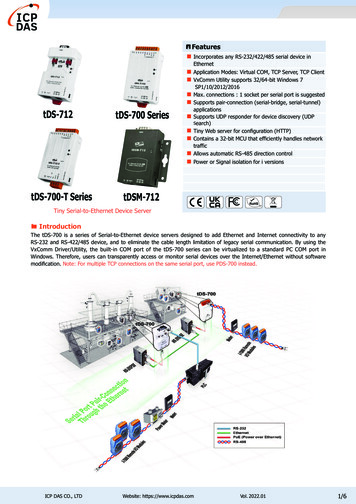
Page 14D.Setup ScreenThis screen is used to choose the calibration procedure for the TD-700.-Simple, Multi-Optional Raw Fluorescence, Multi-Optional DirectConcentration. This screen will have 1 of 3 looks depending upon how theinstrument is currently configured. (See figure to the left).Simple Mode1. ModeTo access the Setup Screen, from the Home screen press ENT then 1 . Press the appropriate number to access the setup parameters.Raw Fluorescence1. Mode. This parameter allows the user to choose between Simple &Multi-Optional calibration modes. (See Section V E for more details).1. Mode2. Cal Procedure2. Cal Procedure. This parameter allows the user to choose between RawFluorescence and Direct Concentration calibration procedures (SeeSection V E for more details.3. Units. Used only in Multi-Optional - Direct Concentration mode only.This is to choose which units your standards and samples aremeasured in.Direct Concentration1. Mode 3. Units2. Cal ProcedureFor all 3 of these parameters, use the - key to toggle between choices.When you have your choice selected, press ESC or H .E.Calibration ScreensThe instrument will initiate the calibration process when 2 of the keypadis pressed from the "Setup/Calibration" Screen. The firmware will guidethe user through the process. Depending upon the calibration mode andprocedure chosen in the Setup screens, the steps will be different. (Seefirmware flowchart on pages 16 & 17). Here is a description of the 3different calibration procedures.Simple: One point calibrationThis calibration allows you to use one standard (or sample) and noblanks. The instrument gives the standard a relative value of 500 on ascale of 0-1000. The instrument uses a preprogrammed absolutezero as the 0 point.Multi-Optional/ Raw fluorescence: two point calibration(standard blank)This calibration allows you to use one standard and the option to blanksubtract. The user can specify the magnitude in relative fluorescenceunits for the standard (on a scale of 0-1000). As an example, if youexpect your standard is 75% of the full range for the application (seeapplication notes on our website for ranges), then call the standard750 RFUs.MultiOptional/Direct Concentration: Multi point calibration(up to 5 standards blank)This calibration allows you to use up to 5 different standards plus ablank for the calibration. You can choose the units of your standards,and define the magnitude of the maximum readable level. In the end,the output can be in direct concentration so no further calculations areneeded.TD-700 Laboratory Fluorometer Operating Manual
Page 15NOTESTD-700 Laboratory Fluorometer Operating Manual
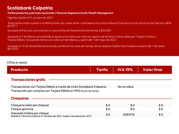
TURNER DESIGNST7-1B 10/96600Power up ScreenCountdown from 600XXX (units) ENT Setup &Cal ENT 1. Setup2. CalibrationHome Screen1Raw Fluor.ModeSimple ModeKDLYXXX (units) ENT -Setup &Cal1. Mode1. Mode2. Cal ProcedureDirect conc.Mode1. Mode3. Units2. Cal ProcedureAVEXXX (units) ENT -Setup &Cal1 Simple Multi-OptionalUse this screen to choosebetween the Simple modeand the other 2 modes2 Raw Fluor. Direct Conc.Use this screen to choosebetween Raw Fluor. anddirect conc. modesENDXXX (units) ENT -Setup &Cal0Blank?1. Yes9. No3Return to homescreenBLKXXX (units) ENT -Setup &Cal7Data Stream? Yes NoPress ENT then D to seeData Rate (sec) 1 2 5 10 30 608Sen%: XXXRaw: XXX.XXPress ENT to seeOper: XXX HrsPwr Level: 100%9TURNER DESIGNST7-1B 10/96600ppbppt ppm ug/lug/ml ng/mlUse the " - " button on thekeypad to toggle between optionsThe option in brackets is theselected optionUse this screen to chooseunits to be displayed on thehome screen
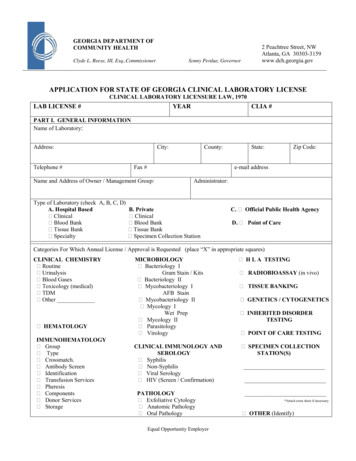
2Simple ModeRaw Fluor.ModeInsert TypicalSample ENT Insert TypicalSample ENT SETTING SensSend Factor: XXSet Sample XXX1. OK 9. ChangeSensitivity SetSens Factor: XXSample XXX ENT Printing CalReport, pls waitSample XXXNew ENT SETTING SensSend Factor: XXSensitivity SetSens Factor: XXSample XXX ENT Read & SubtractBlank?1 Yes 9 NoPress 1 to seeInsert Blankand press ENT Press ENT to seePress 0 whenvalue stableXXXDirect conc.ModeMax range: XXXX1. OK 9. ChangeInsert Blankand press ENT Max conc: XXX.XNew ENT Number of Stds(1-5) X ENT Reading BlankEnter highestconc Std firstCalibrationCompleteHi Std Conc: XXX.X1. OK 9. ChangePrinting CalReport, pls waitHi conc:New WAITXXX.X ENT Insert Hi Stdand press K SETTING SensSend Factor: XXSensitivity SetSens Factor: XXReading Hi StdWAITPress 0 to seeReading BlankWaitBlank XXXPrinting CalReport, pls waitPress 0 whenvalue stable XXX#X Std Conc. XXX.X1. OK9. Change#X conc:New:XXX.X ENT Insert #X Stdand press K Reading:#X stdWAIT
Page 18VI. Calibration OverviewA. Why Calibrate?The TD-700 calibration procedures set the instrument's sample range,(concentration range) and sensitivity based on a chosen fluorescentstandard or sample. In addition, calibration in the Direct Concentrationmode assigns a digital value to a known standard so that subsequentstandards or samples can be easily referenced to the original. For example, during Direct Concentration calibration you can assign a value of500 to a sample and know with certain confidence that a sample thatreads 250 contains half as much analyte as the original sample (assumingthat the blank reads zero).Note: Calibration data will bestored even after power to theinstrument is turned off.B.Note that a separate calibrationis stored for each of the threemodes. For example, if youcalibrate in the Simple Mode,this calibration remains ineffect until you recalibrate inthe Simple Mode. If youcalibrate in the Multi-OptionalMode - Direct Concentration,this will not change thecalibration in the SimpleMode. Similarly, a calibrationin the Multi-Optional Mode Direct Concentration will notaffect a calibration in theMulti-Optional Mode - RawFluorescence.Thus, in effect, the TD-700 canstore three separatecalibrations at the same time,one for each mode. This alsomeans that when you changemodes, as each mode is aseparate function, you mustcalibrate in the mode you wantto use.C.When to Calibrate·For greatest accuracy, calibrate before running a new batch ofsamples.·Recalibrate if the ambient temperature changes by /- 5 C.·Recalibrate after changing lamps, filters, cuvette sizes, or the analyteyou are measuring.·Verify the need to calibrate by reading a stable, known concentrationstandard immediately after calibration and again every few hours tosee if readings have changed significantly. Recalibrate when theaccuracy becomes unacceptable for your study.TD-700 Calibration OptionsThere are three calibration procedures available on the TD-700:· Simple Mode- Raw Fluorescence Calibration· Multi-Optional Mode- Raw Fluorescence Calibration· Multi-Optional Mode- Direct Concentration Calibration1. Simple Mode Calibration: In the Simple Mode calibration procedurethe instrument range is automatically set based on the typicalstandard or sample chosen. You cannot manually adjust theinstrument range when calibrating in this mode. The chosen samplewill be automatically set to 50% of the maximum value that can beaccurately read by the instrument, (500 out of 1000). Also, there is nooption to read and subtract a blank during this calibration procedure.2. Multi-Optional Raw Fluorescence Mode: In the Multi-OptionalMode Raw Fluorescence calibration you may manually adjust theinstrument range by changing the default sample value of 500 toanother number from 100 to 950. If you assign a value higher than 500to your chosen sample, you will decrease the maximum sampleconcentration that can be read and increase the instrument’ssensitivity and resolution. If you assign a value lower than 500, youwill increase the maximum concentration that can be read anddecrease the instrument’s sensitivity and resolution.TD-700 Laboratory Fluorometer Operating Manual
Page 193. Direct Concentration Calibration: Direct Concentration Calibration,only available in the Multi-Optional Mode, is a multi-point calibration inwhich up to five standards and a blank are read. The software usesthese points to set the optimal instrument range and sensitivity, and tocalculate the direct concentration of unknowns. In a multi-pointcalibration, the instrument generates a calibration curve for superioraccuracy. The TD-700 will display the actual concentration of yoursamples. The display units are user-selectable and chosen in thesetup menu.Note: Fluorescence measurements are affected by factors such astemperature, linearity, and instrument drift. Before calibrating orrunning samples for the first time, we recommend reviewing Appendix1.TD-700 Laboratory Fluorometer Operating Manual
Page 20Calibration: Simple ModeVII. Calibration: Simple Mode1. Setup2. Calibration1. Mode Simple Multi-Optional1.The Simple Mode calibration procedure is a single point calibration in which astandard is run in order to set the optimal range and sensitivity of the instrument.The chosen sample will be set automatically to one half of the maximum value thatcan be accurately read by the instrument. You cannot manually adjust theinstrument range and sensitivity during this procedure. Also, there is no option toread and subtract a blank. If you do not require these capabilities, you may wishto use the Simple Mode calibration as it is expedient and straightforward.1.To choose the Simple Mode, press ENT from the HOME screen, press 1 for Setup, then 1 again for Mode. Use to choose the SimpleMode. Press ESC twice to return to the Setup/Cal Screen.2.Press 2 from the Setup/Cal Screen. The Simple Mode calibrationsequence will appear.3.Fill a clean test tube or cuvette with a sample that is about half themaximum concentration you wish to read. You do not need to know theexact concentration; you are using it to set the optimal instrument rangeand sensitivity. Wipe the outside of the test tube or cuvette dry, and insertit into the sample adaptor in the sample chamber.4.The TD-700 will now set sensitivity, as indicated by the SENS FACTOR(sensitivity factor), so that the sample you inserted will read 500 (half ofmaximum) on the HOME screen.1. Setup2. CalibrationInsert TypicalSample ENT SETTING SensSens Factor: XX2.4.Sensitivity SetSens Factor: XXSample XXX ENT Blank: X.XCal Std: XXX.X 1 - Abort Cal ESC - Resume5.7.9.5.Upon finishing the sensitivity adjustment, the screen prompts you toacknowledge the value set by pressing ENT . Then, calibration data willautomatically printout to a printer or a computer and return you to the HOMEscreen. See Appendix 2 for details regarding the calibration printout.6.Errors: After reading the sample, the TD-700 will automatically adjust to theoptimal range for sample measurement. If the sample used is tooconcentrated or too dilute, the instrument may not be able to reach the targetsensitivity. In these cases, a note message will appear indicating that, basedon the calibration, the unit has reached its sensitivity maximum or minimum.By pressing ENT you tell the instrument to accept the maximum orminimum sensitivity value. It is recommended, however, that you adjust yoursample concentrations to fall within range, and then recalibrate.7.To view the last calibration data set, press ENT from the HOME screen,then 9 to view your blank and calibration standard value. Press H toreturn to the HOME screen.8.To print the last calibration data set, press ENT from the HOME screen,then D . Press H to return to the HOME screen.9.To abort the calibration, press ESC at any time during the calibrationsequence. Press 1 to abort or ESC to resume.TD-700 Laboratory Fluorometer Operating Manual
Page 21NOTESTD-700 Laboratory Fluorometer Operating Manual
Page 22Calibration: Multi-OptionalRaw Fluorescence1. Setup2. Calibration1.VIII. Calibration: Multi-Optional Mode - RawFluorescenceThe Multi-Optional Mode - Raw Fluorescence calibration procedure is a singlepoint calibration in which a standard and optional blank are run in order to set theoptimal range and sensitivity of the instrument. The user chooses from a range of100-950 on a scale of 1000, the relative magnitude of the standard. The useralso has the option to subtract the blank signal from all the readings.1. Mode2. Cal ProcedureSimple Multi-Optional 1.To choose the Multi-Optional - Raw Fluorescence Mode, press ENT from the HOME Screen, press 1 for Setup, then 1 again for Mode.Use to choose the Multi-Optional Mode. Press ESC to return tothe previous screen, then press 2 to choose the calibration procedure.Use the key to choose “Raw Fluor.” for the Raw Fluorescencecalibration procedure. Press ESC twice to return to the Setup/CalScreen.2.To access the calibration sequence, press 2 from the Setup/Cal
tion indicators on the cylinder with the silver alignment mark on the inside rim of the sample chamber. Replace the sample adaptor making sure that the adaptor is properly seated in the filter cylinder, and close the sample chamber lid. 8. Plug in the unit. Be sure to use only the Turner Designs power supply provided with your instrument. It is .