Transcription
Wear of PEEK All-Polymer Articulations for Cervical SpinalDisc ArthroplastybyHeather AustinA thesispresented to the University of Waterlooin fulfillment of thethesis requirement for the degree ofMaster of Applied ScienceinMechanical EngineeringWaterloo, Ontario, Canada, 2008 Heather Austin 2008
I hereby declare that I am the sole author of this thesis. This is a true copy of the thesis,including any required final revisions, as accepted by my examiners.I understand that my thesis may be made electronically available to the public.ii
AbstractThe conventional treatment for degenerative disc disease (DDD) and discherniation is spinal fusion, a process consisting of fusing two segments of the spinetogether. Arthroplasty treatments that preserve the natural motion of the spine are still inthe early stages of development. Cervical disc arthroplasty (CDA) involves removal ofthe existing damaged disc and replacement with an articulating implant.The materials used for implants must possess excellent biocompatibility, strength,and wear resistance properties. Spinal implants in particular should also allow precisepost-operative imaging because surgeons rely on imaging tools to check for migration ofthe implant and nerve impingement post-operatively.The purpose of the current thesis is to investigate the wear behaviour of threedifferent versions of poly-ether-ether-ketone (PEEK), a radiolucent polymer that does notdistort MRI images, articulating against themselves. The materials tested include: PEEKOPTIMA (OPT), carbon-fiber reinforced (CFR) PEEK and carbon-nanofiber (CNF)PEEK.A series of wear tests were performed on a pin-on-plate apparatus that imposedreciprocating crossing-path motion to the articulating specimens. The first series of weartests, “normal conditions tests”, consisted of application of 80 N for 2.0 million cycles(Mc). Continuation of testing was aimed at evaluating the tribological behaviour of thematerials under “adverse conditions”. The adverse conditions involved increasing theload every 0.15 Mc until the material showed significant surface damage. The materialswere tested in a 12g/L protein concentration alpha calf fraction serum, at 37 C. The wearof the specimens were evaluated using volumetric wear calculations and microscopy.The lowest wear, at the end of the normal conditions test, occurred with thearticulation of CFR PEEK-on-CFR PEEK, and the highest wear, after 2.0 Mc, occurredwith CNF PEEK-on-CNF PEEK. The adverse conditions revealed the highest wear valuefor PEEK OPT. Surface damage was apparent on both the PEEK OPT and CFR PEEKspecimens; however, volumetric wear measurements performed on the specimens did notindicate a rise in wear for CFR PEEK, though surface damage was visibly noted. CNFiii
PEEK was not tested to failure, although surface damage was evident as the materialneared the end of the adverse conditions test.The PEEK OPT wear values after the normal conditions test are similar to thosereported for spine simulator studies on a PEEK OPT-on-PEEK OPT all-polymer lumbarnucleus implant. This tentatively suggests that the normal test conditions represent aclinically realistic range.CFR PEEK shows the most promise for application in cervical disc arthroplasty.The other versions of PEEK possess excellent imaging qualities but had inferior wearresistance compared with CFR PEEK. However, wear volumes found in the presentthesis for all three versions of PEEK after the “normal conditions” test were considerablylower than those found for stainless steel (SS) in similar testing. Prestige STLP,composed of SS, is an FDA approved product that is currently implanted in patients inthe United States.iv
AcknowledgmentsI would like to extend thanks to my supervisor, Dr. J.B. Medley, for providing mewith many opportunities, including the chance to observe orthopaedic surgery and theexperience of travelling to both local and international conferences. Dr. J.B. Medley’schallenge of my results and reasoning has led to a much improved thesis and a deeperunderstanding of the material presented. Dr. C.M. Hanson is credited for me maintainingmy sanity towards the end of this project. Thank you for taking on the task of cosupervision and for your constant support and insight into my research.I would like to thank my research group consisting of Kyle Anders, BradBergsma, Neal Damgaard, Rana Islam, Shahzma Jaffer, Katherine Olsen and Ken Su forall the feedback. Thank you to Dan Langohr for his assistance with experimentalprocedures.I am grateful for the financial support from Medtronic Spinal and Biologics,Memphis, TN. Many thanks to Megan Harper for her expertise in wear research. Thankyou to Jan Brandt for his insight into lubricant composition. The precise resultspresented in this thesis would not have been possible without the help of the team atLondon Health Sciences Centre who graciously lent me their analytical balance for theduration of my research.Thank you to Tom Gawel for the design and fabrication of the load soak usedthroughout this project and for the technical support provided when issues arose with theOrthoPODTM. I would like Charlie Boyle, from the University of Waterloo machineshop, for fabricating the specimen holders used in the wear tests.Thank you to my family and friends for your support and patience throughout thisendeavor. Finally, thank you Tom and Ruby for making me laugh at least once day,everyday.v
DedicationThe current thesis is dedicated to the following individuals:Sandy AustinDon AustinStephanie WoodNeil GibsonKirk D’SouzaDr. M. J. BerberThank you.vi
TABLE OF CONTENTSList of Tables . ixList of Figures . xList of Equations . xiiNomenclature. xiii1.0INTRODUCTION . 12.0LITERATURE REVIEW . 32.1.Anatomy and Biomechanics of the Cervical Spine . 32.1.1.General Anatomy . 32.1.1.Loads and Motions of the Cervical Spine. 52.1.2.Intervertebral Disc . 112.2.Basic Tribology. 132.2.1.Surface Topography. 142.2.2.Friction. 162.2.3.Lubrication. 162.2.4.Wear. 182.3. Surgery for Damaged Cervical Discs . 222.3.1.Fusion. 222.3.2.Cervical Disc Arthroplasty . 232.3.2.1.Implant Design Principles. 232.3.2.2.Implants. 242.3.2.3.Biomechanical and Wear Tests. 282.3.2.4.Wear Particles and Osteolysis. 302.3.2.5.Evidence of Osteolysis in Spinal Disc Arthroplasty. 322.3.2.6.Post Operative Medical Imaging . 332.4Polyetheretherkeytone (PEEK). 342.4.1Types of PEEK . 352.4.2Properties . 372.4.3Wear Testing of PEEK Surfaces. 382.4.3.1 Configurations. 382.4.3.2 Reciprocating Pin-on-plate Wear Results. 402.4.3.3 PEEK Simulator Studies . 412.4.3.4 Lubricants . 432.4.3.5 Wear Particles . 432.4.3.6 Fluid Adsorption . 442.5Objectives and Scope of Research. 453.0WEAR TESTING OF PEEK . 463.1.Test Apparatus . 463.1.1Pin-on-Disc Apparatus. 463.1.2Temperature . 473.1.3Chamber Sealing. 473.1.4Hardware and Software. 505.1.1.Motion. 523.1.6Load . 533.2 Load-Soak Apparatus. 543.2.1Design & Fabrication. 54vii
4.0MATERIALS AND METHODS. 564.1.Specimens . 564.2.Protocols . 584.2.1.Lubricant . 614.2.2.Dis-assembly and Cleaning. 634.2.3.Weighing and Re-assembly . 644.2.4.Wear Measurements. 654.2.5.Contact Stress. 664.2.6.Microscopy . 684.3.Concluding Remarks. 685.0RESULTS AND DISCUSSION . 695.1.Preliminary Tests . 695.1.1.Effect of Fluid Composition, Temperature and Load on Fluid Uptake. 695.1.2.Fluid Uptake – Load Soak vs. OrthoPODTM . 715.2.Normal Conditions. 735.2.1.PEEK OPTIMA . 735.2.2.CFR PEEK . 755.2.3.CNF PEEK Wear Curves. 765.2.4.Comparison of PEEK OPTIMA, CFR PEEK and CNF PEEK . 775.2.4.1.Comparison of Wear Rates for Different Contacts. 795.2.4.2.Comparison of Wear Rates for Various PEEK pin-on-plate Studies . 815.3. Observations on the Effect of Protein Degradation on Wear . 825.4.Adverse Conditions. 845.4.1.Wear Curves for PEEK OPTIMA, CFR PEEK and CNF PEEK . 845.4.2.Modes of Failure . 875.5.Microscopy of Surface Failure. 885.5.1.PEEK OPTIMA . 895.5.1.1.SEM . 915.5.2.CFR PEEK . 945.5.2.1.Scanning Electron Microscopy . 945.5.3.CNF PEEK. 985.6.Concluding Remarks. 985.7.Clinical Implications. 996.0CONCLUSIONS AND RECOMMENDATIONS . 1016.1.Conclusions. 1016.2.Recommendations. 103References. 105AppendicesAPPENDIX A. 114APPENDIX B . 125APPENDIX C . 127APPENDIX D. 134APPENDIX E . 136viii
List of TablesTable 1: Motions for C3-C7 segments in the Cervical Spine . 6Table 2: ISO & ASTM Standards for Loads and Motion. 9Table 3: FDA Summary of Safety and Effectiveness Data Report Results- Prestige [21]. 29Table 4: FDA Summary of Safety and Effectiveness Data Report - ProDisc-C [20]. 29Table 5: Wear Results for the Bryan [7] . 30Table 6: PEEK Properties . 37Table 7: Comparison of Pin-on-plate tests with Different Articulating Materials and TestConditions . 40Table 8: Specimen Pairings . 57Table 9: Preliminary Test Protocol . 59Table 10: PEEK OPTIMA Test Protocol. 60Table 11: CFR PEEK Protocol . 61Table 12: CNF PEEK Protocol . 61Table 13: Bovine Lubricant . 62Table 14: Alpha Lubricant . 62Table 15: Volumetric Wear & Wear Factors for PEEK OPTIMA - Normal Conditions 74Table 16: Volumetric Wear and Wear Factors for CFR PEEK - Normal Conditions. 76Table 17: Volumetric Wear and Wear Factor for CNF PEEK - Normal Conditions . 77Table 18: Average Volumetric Wear Values after 2.0 Mc for PEEK OPT, CFR PEEK &CNF PEEK. 78Table 19: Adverse Conditions Wear Results . 85Table 21: Percentage of Wear Experienced by the Pin and the Plate. 98ix
List of FiguresFig. 1: Bryan Cervical Disc Implant (Medtronic ) [7] . 1Fig. 2: Regions of the Spine ( Top Left [17], Bottom Right [16]). 4Fig. 3: Motions of the Spine [18]. 5Fig. 4: Cervical Disc Segment: Forces, Translations, Rotations [19]. 6Fig. 5: Cervical Intradiscal Pressures and Axial Loads [12, 18] . 10Fig. 6: Intervertebral Disc [25] . 12Fig. 7: Facet Joints[15] . 13Fig. 8: A worn surface of 20wt% commercial grade PAN CFR PEEK pin afterarticulating against a 100Cr6 steel plate [45] . 14Fig. 9A&B: Micrographs of PEEK OPT - Normal vs. Severe Test Conditions [45, 46] . 15Fig. 10: Micrograph of 30wt% PAN CFR PEEK - Severe test conditions [46]. 16Fig. 11: Types of Lubrication [48]. 17Fig. 12: Typical Wear Behaviour [44]. 20Fig. 13: The Transition Phenomena in Wear [50] . 21Fig. 14: Prestige LP (Medtronic Spinal a Biologics) [6] . 25Fig. 15: ProDisc-C (Synthes, Paoli, PA) [62]. 26Fig. 16: Bryan Cervical Disc Implant (Medtronic Sofamor Danek) [64][66] . 27Fig. 17: PCM (Cervitech , Rockway, NJ) [68, 68] . 28Fig. 18: MRI of A) ProDisc-C B) PCM [11] . 34Fig. 19: Radiopacity of Different Spinal Implants [13]. 36Fig. 20: PEEK vs. UHMWPE [85] . 42Fig. 21: Schematic of OrthoPODTM [108]. 46Fig. 22: OrthoPOD lubricant levels after 0.2 Mc cycles. 48Fig. 23: Fluid Level Difference between Chamber 1 and Chamber 4 . 48Fig. 24: Volume of lubricant in the OrthoPODTM and Load Soak . 49Fig. 25: Incorrect “Home” Position . 51Fig. 26: Load Soak Apparatus . 55Fig. 27: Specimens A) Pin B) Plate . 56Fig. 28: Confirm of Radius on Pins (PEEK OPT) . 57Fig. 29: Numbering Scheme for A) OrthoPODTM B) Load Soak. 58Fig. 30: Wear Paths on PEEK OPTIMA Specimen. 59Fig. 31: Effect of Temperature (Above Left) & Load (Above Right) on Fluid Uptake –Study 1 . 70Fig. 32: Effect of Temperature and Load - Study 2. 70Fig. 33: Change in Mass (mg) for PEEK OPTIMA pairs (plate pin) . 71Fig. 34: Fluid Uptake Test A) Original Location B) Reversed Location . 72Fig. 35: Average Fluid Uptake Study A) Original Locations B) Locations Reversed . 72Fig. 36: PEEK OPTIMA Wear Curves. 74Fig. 37: CFR PEEK Wear Curves. 75Fig. 38: CNF Wear Curves . 76Fig. 39: Normal Conditions Wear Curves . 78Fig. 40: Comparison of Results and Studies from the Literature (wear rates 20 mm3/Nmx 10-7) . 80Fig. 41: Comparison of PEEK Wear Rates. 81x
Fig. 42: Comparison of Results to PEEK studies from the literature (2 studies not shownin graph) . 82Fig. 43: Protein Degradation and Wear Curves for PEEK OPTIMA Normal Condtions 83Fig. 44: Wear Curves for Adverse Condition Tests. 85Fig. 45: Volumetric Wear of All Versions of PEEK after Normal and AdverseConditions . 86Fig. 46: PEEK OPTIMA – Plate 2 at the 300 N load level of the Adverse Conditions Test. 87Fig. 47: CFR PEEK – Plate 2 at the 400N load level of the Adverse Conditions Test . 88Fig. 48: Worn End of CFR Pin 1 and OPT Pin 2. 88Fig. 49: Macrographs of PEEK OPT Plates 2 & 4 after Adverse Conditions Test (300N,2.75 Mc). 90Fig. 50: Overview of Damaged Region on PEEK OPT Plate 2. 91Fig. 51: Different Locations in the Damaged Zone – PEEK OPT (plate 4) . 92Fig. 52: Microscopy of Plate 5 - Unworn (A) and Plate 4 - Severely Damaged (B) PEEKOPT . 93Fig. 53: Pin 4 after Adverse Conditions (300N, 2.75 Mc). 93Fig. 54: Damage seen at 2.90 Mc and 350 N - CFR PEEK Plate 2 A) Centre of hole B)Polished wear track . 95Fig. 55: Images of Unworn (A) and Severely Damaged (B) CFR PEEK Plate 3. 96Fig. 56: Max Damage in A) PEEK OPT – Plate 2 @ 2.75 Mc, 300N and in B) CFRPEEK – Plate 2 @ 3.05 Mc, 400 N. 96Fig. 57: Pin hole damage on a CFR PEEK pin specimen after 2.9 Mc and 350 N. 97Fig. 58: Carbon Fiber Orientation in Pin and Plate Specimens . 97Fig. 59: CNF PEEK plate @ 0.25 Mc, 80 N. 98xi
List of EquationsEqn. 1: Definition of the Coefficient of Friction [47]. 16Eqn. 2: Archard's Law [44]. 21Eqn. 3: Wear in mg . 65Eqn. 4: Volumetric Wear . 65Eqn. 5: Wear Factor . 66Eqn. 6: Contact Stress Formula [110]. 67Eqn. 7: Hertzian Theory. 67xii
SOkPaLBLCMcNOPTPANPEEKROMSDSSTiCTMUHMWPECervical Disc ArthroplastyCervical Disc ArthroplastyCarbon Fibre ReinforcedCarbon NanofiberCobalt chromium molybedeumComputer TomographyDegenerative Disc DiseaseFlexion/ExtensionHigh carbonHertzInternational Standard OrganizationkiloPascalsLateral BendingLow carbonMillion r-ketoneRange of MotionStandard DeviationStainless SteelTitanium CarbideTrade MarkUltra High Molecular Weight PolyethyleneMATHEMATICAL SYMBOLSΔVµρmNπxVKChange in VolumeCoefficient of frictionDensity of the specimenmassNumber of samplespisliding distanceVolumetric wearWear Factorxiii
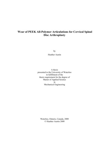
1.0 INTRODUCTIONCervical degenerative disc disease (DDD), which can include facet jointdegeneration and cervical disc herniation result in tingling and clumsiness of the handsand possible gait disturbance. DDD and disc herniation also affect the roots of the nervesthat run along the spine and can result in shoulder and arm pain [1]. If untreated, severeDDD or disc herniation can lead to loss of normal disc mechanical function, tissue injury,pain and ultimately paralysis. Less severe cases can be treated with physiotherapy,braces and other non-surgical devices therapies but spinal fusion, the fusion of two ormore vertebrae to form a single rigid unit, is the conventional treatment for severecervical DDD and disc herniation. Adjacent disc degeneration, above or below a fusedsegment, is not uncommon and can create a need for additional fusions in the future [2].This increasingly impairs motion and overall functionality of the cervical spine.Cervical disc arthroplasty (CDA), in which the intervertebral disc between twoadjacent vertebrae is replaced by an articulating implant, is a relatively new andincreasingly popular surgical procedure used to treat DDD or cervical disc herniation [3].It preserves the natural motion of the spine and, thus, reduces the risk of adjacent discdegeneration [3]. CDA implants include the articulation of the following classes ofmaterials; metal-polymer [4], ceramic-ceramic [5] and metal-metal [6]. Fig. 1 shows ametal-polymer CDA implant known as the Bryan .Fig. 1: Bryan Cervical Disc Implant (Medtronic ) [7]1
Wear particle-induced osteolysis, a time dependent process that arises from aninflammatory reaction to wear particles, can result in loosening of an implant. Inaddition, it is the main cause of hip replacement failure [8, 9] but is not life threatening.Loosening of a cervical implant, and possible migration, however, is a major concern dueto the implant being situated adjacent to neural structures. Explant analysis [10] ofmetal-polymer and metal-metal implants has not shown wear particle-induced osteolysisbut there has been some inflammatory response. Further clinical follow-up is requiredbecause the results of the explant analysis have been obtained only after short termimplantation.Almost all of the implant designs use tough, relatively rigid metallic materials topromote a stable fixation at the implant-bone interface. However, to varying extents,metals impair the clarity of medical imaging [11]. Obtaining quality images postoperatively is important because examination and confirmation of the decompression ofneural structures is often required after CDA. Ability to see the implant and adjacentstructures is imperative [11]. A radiolucent polymer implant would not distort MRI andcould be an alternative to the conventional materials used in cervical implants. Structuralstrength, implant-bone interface stability and, in particular, wear resistance must beconfirmed to deem a new material acceptable.Medical grade polyetheretherketone (PEEK) is a polymer that has structuralstrength and stiffness to provide a stable implant-bone interface [12]. In addition, PEEKis a radiolucent polymer that does not distort MRI images [13]. Initial pin-on-plate wearof
The conventional treatment for degenerative disc disease (DDD) and disc herniation is spinal fusion, a process consisting of fusing two segments of the spine together. Arthroplasty treatments that preserve the natural motion of the spine are still in the early stages of development. Cervical disc arthroplasty (CDA) involves removal of