Transcription
BSAGINAWCONTROL & ENGINEERING A/C USER MANUAL1User Manual SCE-AC1000B120V, SCE-AC1000B120VSS & SCE-AC1000B120VSS61. User Manual. p. 22. Legal Regulations. p. 23. Safety Instructions. p. 34. Functional Principle. p. 45. Technical Data. p. 56. Performance Graph. p. 67. Mounting. p. 78. Mounting Principle. p. 79. Cutout Dimensions. p. 810. Dimensions (H x W x D). p. 811. Electrical Connection. p. 912. Controller Programming. p. 913. Wiring Diagram. p. 1314. Taking Into Operation. p. 1515. Repair. p. 1516. Maintenance & Cleaning. p. 1617. Transport & Storage. p. 1618. Parts Supplied. p. 1619. Warranty / Limits of Liability. p. 17
BSAGINAWCONTROL & ENGINEERING A/C USER MANUAL21. User ManualThis instruction manual contains information and instructions to enable the user to work safely, correctly and economicallyon the unit. Understanding and adhering to the manual can help one: Avoid any dangers Reduce repair costs and stoppages Extend and improve the reliability and working life of the unitPLEASE ENSURE TO USE THE RIGHT VERSION OF THE INSTRUCTION MANUAL SUITABLE FOR YOUR UNITConditions of UseThe unit is to be used exclusively for the dissipation of heat from control cabinets and enclosures in order to protecttemperature sensitive components in an industrial environment. To meet the conditions of use, all the information andinstructions in the instruction manual must be adhered to.General DangerIndicates compulsory safety regulations which are not covered by a specific pictogram suchas one of the following.High Electric VoltageIndicates electric shock danger.Important Safety InstructionIndicates instructions for safe maintenance and operation of the unit.AttentionIndicates possible burns from hot components.AttentionIndicates possible damage to the unit.InstructionIndicates possible danger to the environment.2. Legal RegulationsLiabilityThe information, data and instructions contained in this instruction manual are current at the time of going to press. Wereserve the right to make technical changes to the unit in the course of its development. Therefore, no claims can beaccepted for previously delivered units based on the information, diagrams or descriptions contained in this manual. Noliability can be accepted for damage and production caused by: Disregarding the instruction manualOperation errorInappropriate work on or with the unitThe use of non-specified spare parts and accessoriesUnauthorized modifications or changes to the unit by the user or his personnelSaginaw Control & Engineering is only liable for errors and omissions as outlined in the guarantee conditions contained inthe main contractual agreement. Claims for damages on any grounds are excluded.back to top
BSAGINAWCONTROL & ENGINEERING A/C USER MANUAL33. Safety InstructionsUpon delivery the unit is already meeting current technical standards therefore it can be safely taken into operation. Onlytrained specialists are allowed to work on the unit. Unauthorized personnel must be prohibited from working on the unit.Operating personnel must inform their superiors immediately if any malfunction of the unit becomes apparent.Please note that before starting to work on or with the unit, a procedure must be carried out inside the cabinet on which theunit is to be mounted.Before commencing work inside the cabinet, the control cabinet manufacturer’s instruction must be read with regards to: Safety instructions Instructions on taking the cabinet out of operation Instructions on the prevention of unauthorized cabinet reconnectionThe electric equipment meets the valid safety regulations. One can find dangerous voltage (above 50V AC or above 100VDC): Behind the control cabinet doors On the power supply in the unit housingThe units have to be fused according to the type plate and the wiring diagram. Switch the unit off immediately if the electricpower supply is interrupted.Danger Through Incorrect Work on the UnitOnly specialized personnel are allowed to maintain and clean the unit. Regular maintenanceand cleaning must be kept in order to ensure that the unit remains in perfect working conditionand has a long working life.Danger from Electric VoltageOnly specialized personnel are allowed to maintain and clean the unit. The personnel mustensure that for the duration of the maintenance and cleaning, the unit is disconnected fromthe electrical supply.AttentionDamage to the unit through the use of inappropriate cleaning materials. Please do not useaggressive cleaning material.InstructionDamage to the environment through unauthorized disposal. All spare parts and associatedmaterial must be disposed of according to the environmental laws.back to top
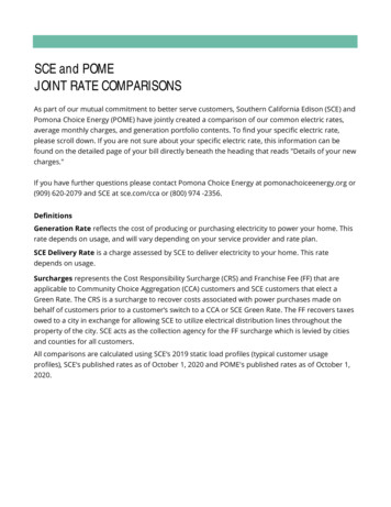
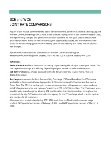
BSAGINAWCONTROL & ENGINEERING A/C USER MANUAL44. Functional PrincipleThe unit functions on the principle of the compression refrigerator. The main components are: refrigerant compressor,condenser, choke and evaporator. These four components of the refrigerant plant are connected with each other by pipesto form a hermetically sealed system in which the refrigerant (R134a) circulates.1. Air Intake, Cabinet Side2. Radial Fan, Cabinet Side3. Evaporator4. Air Outlet, Cabinet Side5. Compressor6. Air Intake, Ambient Side7. Radial Fan, Ambient Side8. Condenser9. Air Outlet, Ambient Side10. Filter Dryer11. Capillary Pipeback to top
BSAGINAWCONTROL & ENGINEERING A/C USER MANUAL55. Technical DataPart NumbersCooling Capacity @ 95 F / 95 FCooling Capacity @ 131 F / 131 FHeating CapacityCompressorRefrigerantRefrigerant ChargeMax. PressureOperating Temperature RangeMax. Air Volume FlowMountingHousing MaterialDimensions (H x W x B120VSS61000 BTU (293 Watts)875 BTU (256 Watts)150 WReciprocating CompressorR134a4.00 oz428 / 88 psig-4 F - 140 FAmbient Air Circuit: 50 cfmCabinet Air Circuit: 50 cfmExternalMild Steel, Powder CoatedSS: Stainless Steel AISI 304SS6: Stainless Steel AISI 31618.90 x 9.84 x 7.50 inch34.0 lbsCutout Dimensions8.0 x 9.8 inchRated Operating Voltage / Frequency120 V - 60 HzRated Current @ 95 F / 95 FStarting CurrentMax. Current2.4 A8A2.9 APower Consumption @ 95 F / 95 F270 WMax. Power Consumption330 WFuse RatingSCCRCircuit Breaker – MCB Type D or K Slow Acting5A (T) - Time Delayed [Slow Acting]5kA5A Slow ActingConnectionConnection Terminal BlockNEMA Protection ClassNEMA 3, 3R, 4 & 12SS: NEMA 3, 3R, 4, 4X & 12ApprovalsCE / cURus / UL ListedIndustry StandardsIS19SS: IS20Sound Level at 1.5 meters65 db(A)Max Voltage at Door Switch5 A DCback to top
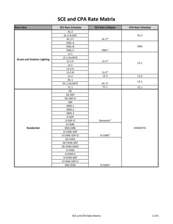
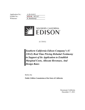
BSAGINAWCONTROL & ENGINEERING A/C USER MANUAL66. Performance GraphEnviro-Therm Air Conditioners 1000 BTU/HR (293Watts)Performance Curve SCE-AC1000B230V, SCE-AC1000B120VSCE-AC1000B230VSS, SCE-AC1000B120VSSSCE-AC1000B230VSS6, SCE-AC1000B120VSS6Enclosure Air Temp131 F/55 C122 F/50 C95 F/35 C68 F/20 CAmbient Temperature ( 065758595105115125(Watt)1100Cooling CapacityCooling Capacity1200205135Ambient Temperature ( F)back to top
BSAGINAWCONTROL & ENGINEERING A/C USER MANUAL77. MountingAlways disconnect the power supply before opening the unit.Heat load to be dissipated from enclosure should not exceed specific cooling output of the unit at any condition. Whenselecting a cooling unit, always allow for a safety margin of at least 15% extra cooling output in the worst conditions. Airinlets and outlets must be completely free from obstruction.Ensure that flows of air leaving and entering the cooling unit, internal and external, are not obstructed. Cooling unit enclosureair suction hole must be installed at the highest possible point. When installing the unit on a door ensure it can take theweight.Before drilling the enclosure, ensure the fixing elements and couplings will not interfere with the equipment inside theenclosure itself. Disconnect power before starting any work inside the enclosure. Following this 1:1 Scale Drilling Template,drill the holes and make the required cuts on the enclosure. This template may have been affected by storage conditions,please check this template by verifying values of the largest dimensions before drilling. Fit the sealing strip to the coolingunit on the side connected to the enclosure and follow the installation diagram.8. Mounting Principle1. M6 Bolts2. M6 Toothed Washers3. M6 Flat Washers4. Enclosure! Do not use within the first 15 minutes after installation! Use only the supplied mounting hardware. Tighten fasteners to 40 inch lb. Ensure the mounting surface does not warp after assemblyand reinforce it if necessary.5. Mounting Gasket6. Cooling Unitback to top
BSAGINAWCONTROL & ENGINEERING A/C USER MANUAL89. Cutout Dimensions9.858.837.88.79.99Center Line5.5210.24Cutout18.916.30Ø .26(x7)6.3010. Dimensions (H x W x D)back to top
BSAGINAWCONTROL & ENGINEERING A/C USER MANUAL911. Electrical ConnectionThe cooling unit is used where heat needs to be dissipated from electrical control cabinets or similar enclosures in order toprotect heat sensitive components. The unit has two completely separate air circuits which ensure that the clean cabinetair does not come into contact with the ambient air which may well be dirty or polluted. Control cabinet air conditioners candissipate large quantities of heat from sealed enclosures, such as control cabinets, into the ambient air and at the same timereduce the cabinet internal temperature to below that of the ambient air.The control cabinet air conditioner can function without problems in extreme ambient conditions (e.g. dusty and oily air)with a standard operating temperature ranging between -4 F and 131 F. The stated cooling capacities are according to DIN3168.Door SwitchThe unit can be switched on and off via a door contact switch. When delivered the door contact terminals are bridged onthe female connector. To connect the door contact switch, remove the bridge and connect door contact switch. The contactmust be closed when the cabinet door is closed.12. Controller ProgrammingThe cooling unit is intended to be used as a complementary accessory to larger industrialequipment. The unit is used where heat needs to be dissipated from electrical controlcabinets or similar enclosures in order to protect heat sensitive components. It is notintended for household use. The unit has two completely separate air circuits whichensure that the clean cabinet air does not come into contact with the ambient air whichmay well be dirty or polluted. Enclosure cooling units can dissipate large quantities ofheat from sealed enclosures such as electrical enclosures into the ambient air and atthe same time reduce the cabinet internal temperature to below that of the ambient air.The unit can function without problems in extreme ambient conditions (e.g. dustyand oily air) with a standard operating temperature ranging between 10 C and 55 C. Units can be ordered with an additional electrical cabinet heater. For thecooling capacities and environmental ratings please refer to the type plate data.Controller1234BMSR!PRGDTESTSETThe display shows the temperature in the range of -50 C to 150 C (-58 F to 302 F). Thetemperature is displayed with resolution of tenths between -19.9 C and 99.9 C (-3.8 Fto 211.8 F). During programming, it shows the codes and values of the parameters. Thedisplay also shows icons according to occurring events.back to top
BSAGINAWCONTROL & ENGINEERING A/C USER MANUAL10Display iconsIconFunctionDescription1234Compressor relay activeAlarm relay activeHeater relay activeAmbient blower relay activeFlashes when activation is delayed or inhibitedby protection times, external disabling, or otherprocedures in progress!AlarmFlashes when alarms are activeRHeating modeSignals operation of unit in heating modeDCooling mode in progressActivated only by manual procedureProgrammingThe operating parameters can be modified using the front keypad. Access differsdepending on the type of parameter. Access to configuration parameters is protectedby a password that prevents unwanted modifications or access by unauthorised persons.Setting cooling set point, St1:PRGSET1. Press and hold “SET” until the display shows St1. Once released the pre-set value of St1 will appear.(default: 35 C / 95 F)2. Reach the desired value by using or .3. Press “SET” again to save the new value of St1.Setting heating set point, St2 (only for units supplied with internal heater):PRGSET1. Press “SET” twice slowly and display should show St2 and then the pre-set value of St2. (default: 5 C / 41 F)2. Reach the desired value by using or .3. Press “SET” again to save the new value of St2.back to top
BSAGINAWCONTROL & ENGINEERING A/C USER MANUAL11Setting temperature units ( C / F), low temperature alarm and high temperature alarm:PRGSET1. Press “PRG” button for 5 seconds to reach the modifiable parameter list.2. Use or to reach the desired parameter: C18 for temperature unit of measure C 0 F 1 P25 for low temperature alarm threshold (default -10 C / 14 F) P26 for high temperature alarm threshold (default 55 C / 131 F)3. Press “SET” on the desired parameter to display the current value.4. Use or to reach the desired value.5. Pressing “SET” temporarily saves the new value and returns to the parameters list.6. Repeat steps 2-5 to set other parameters.7. Press “PRG” for 5 seconds to permanently save the new values.Test FunctionDifferent test functions can be used depending on the combination of keys pressed. Such tests run forthe duration of 4 minutes. “SET ” tests Compressor and Ambient Blower relays. “SET ” tests Alarms and Heater relaysback to top
BSAGINAWCONTROL & ENGINEERING A/C USER MANUAL12Alarm Relay FunctionBoth normally closed (NC) and normally open (NO) alarm contacts are provided. These refer to the alarmstate. Under normal conditions, the NC contact is closed and the NO contact is open. When an alarmcondition is present or the door contact is open, the NC contact will open and the NO contact will close.System power failure will give an alarm condition.State1 System powered OFFDisplayAlarm Relay13 14 152 System powered ON-NO ALARM-Door Contact Closed13 14 153 System powered ON-Door Contact Open13 14 154 System powered ON-ALARM STATE13 14 RGTESTSETNotes:State 2: Additional icons (1,3,4, Reverse, Direct, Test) depending on operation.State 3: The display shows “OFF” alternating with the standard display.State 4: The display shows “EXX” alternating with the standard display – at the same time, the alarmicon flashes.Typical alarm codes:Error Code DescriptionE01Probe B1 faultE02Probe B2 faultE04High temperature alarmE05Low temperature alarmImportant Notes Whilst programming, if no button is pressed for 10 seconds, the display starts flashing, and after 1minute returns to the main display without saving changes. l To increase scrolling speed, press and hold the or button for at least 5 seconds. When pressing “PRG” for 3 seconds, the firmware revision code is displayed for 2 seconds. When cleaning the controller panel, do not use ethanol, hydrocarbons, ammonia or their byproducts.Use neutral detergents and water. In order to protect the unit’s components, minimum relay output on (3 or 7 minutes) and off (4minutes) times and minimum time (7 or 11 minutes) between activation of the same relay output areapplied. In case of digital inputs not configured, probes not fitted or configured, or St2 not enabled on thecontroller the display shows ‘nO’.back to top
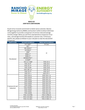
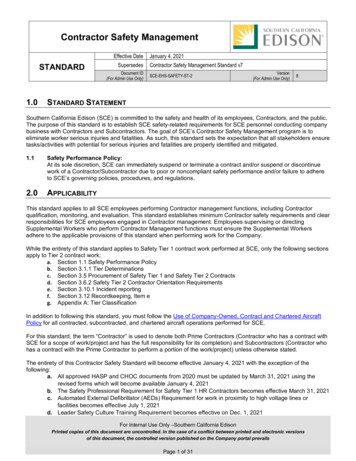
BSAGINAWCONTROL & ENGINEERING A/C USER MANUAL1313. Wiring DiagramMcCompressorMaAmbient FanMiInternal FanCcCompressor CapacitorIHInternal HeaterTSTemperature SensorCECondensate EvaporatorCHCompressor HeaterCControllerARAlarm RelayX4Electrical Supply Connections1 L1 - 120V2 Neutral/N - 120V3 Earth/Ground4 P1 High Temp alarm NO5 P2 High Temp alarm COM6 P3 High Temp alarm NC7 T1 Door Switch Contact8 T2 Door Switch ContactNotes:#1X6 is plugged into X5 for units with heaterback to top
BSAGINAWCONTROL & ENGINEERING A/C USER MANUAL14back to top
BSAGINAWCONTROL & ENGINEERING A/C USER MANUAL1514. Taking Into OperationAttention!The unit can be damaged by lack of lubricant. To ensure that the compressor is adequately lubricated, the oil, which hasbeen displaced during transport, must be allowed to flow back into it. The unit must therefore be allowed to stand for atleast 30 minutes before being connected to the mains and taken into operation. Upon connection the internal fan will startworking. If the temperature inside the enclosure is higher than the set value of the controller, both the compressor andexternal air fan start working. Once the air inside the enclosure reaches the set temperature, the compressor and externalfan will stop.The unit is pre-set at 95 F, which is suitable for most of the electronic devices.If Drainage required, use PVC 10mm (3/8 inch) ID Hose.15. RepairFailureConditionCauseSolutionInternal fan does not workPower not connected.Verify power supplyEnclosure temperature isbelow setting temperature (St)Verify values of parameter "St"Door switch contact is openVerify door switchController does not workReplace controllerThe sequence of the phasesinside the power supplyconnector is incorrectChange phases inside powersupply connectorCompressor motor electricalfailureVerify external fan, verifyambient temperature, cleancondenserInternal fan works, external fanand compressor do not workUnit DoesNot CoolInternal fan works, externalfan and compressor do notwork Display shows alternating"OFF" and temperatureExternal and internal fan work,compressor does not workCapacitor for compressor failed Replace capacitorEnclosureCompressor works, externalfan does not workExternal fan needs to bereplacedReplace external fanCompressor and fans (externaland internal) work all the timeUnit cooling undersizedEnclosure needs a biggercooling unitThermal compressor protectortriggeredVerify ambient temperature,clean condenserRefrigerant leakageContact dealer/service centerAmbient air gets into theenclosureEnsure door is closed, add adoor switch and connect it tocontrollerEnclosure IP degree minimumIP54Seal openings on enclosureDamaged/misplaced sealingstripRepair strip accordinglyOverheating Enclosure needs a biggercooling unitDoor enclosure openExcessiveCondensateDoor enclosure closedback to top
BSAGINAWCONTROL & ENGINEERING A/C USER MANUAL1616. Maintenance & CleaningAlways switch power supply off before starting any maintenance on the unit.Any repairs that may be needed must only be done by qualified personnel. The cooling unit is a low maintenance type andfor most environments, no filter is required. If an air filter is installed, check it periodically for dirt and clogs. Clean or replacefilter when necessary.DisposalThe cooling unit contains R134a refrigerant and small quantities of lubricating oil. Replacement, repairs and final disposalmust be done according to the regulations of each country for these substances.17. Transportation & StorageDuring transport and storage the cooling unit must be kept in the position marked on the box and at a temperature between-40 F and 158 F and a relative humidity of max. 95% (at 77 F). Check that the packaging has not been damaged duringtransport.18. Parts Supplied1 x Air Conditioner1 x Instruction Manual with technical information1 x Mounting Template in 1:1 scale1 x Installation pack containing:7 x M6 Bolts7 x A6.4 Toothed Washers7 x A6.4 Washers1 x Internal Air Deflector1 x Female Connector with shorted wired positions for door contactSaginaw Control and Engineering95 Midland RoadSaginaw, MI 48638-5770Phone: (989) 799-6871Fax: (989) 799-4524sce@saginawcontrol.comback to top
BSAGINAWCONTROL & ENGINEERING A/C USER MANUAL1719. Warranty / Limits of LiabilityAll goods manufactured by SCE shall be warranted to be free of defects in material or workmanship for a period of two yearsfrom the date of shipment. Should the product be proven to SCE to be defective, we shall option to repair or replace theproduct. At no time will SCE reimburse purchaser for unauthorized rework on any product.Air Conditioners & Heat Exchangers are warranted on parts and service for a period of two years from the date of shipmentby Saginaw Control and subject to the following conditions and exclusions:All Goods must be installed and operated according to the following specifications: Maximum voltage variation nogreater than plus or minus 10% of nominal rating; Maximum frequency variation no greater than plus or minus 3Hz. from nominal rating; Must not exceed minimum and maximum rated temperatures; Must not exceed (BTU/Hr)rating; Filters must be cleaned regularly; Must be installed and grounded in accordance with all relevant electricaland safety codes, as well as the National Electric Code and OSHA rules and regulations; Must be installed in astationery application, free of vibration.Our warranty does not warranty product that has been modified, subjected to abuse, negligence in operation ormaintenance, or if product is used in a manner that exceeds its designed capabilities and rating.Warranty related claims will be returned to the factory for evaluation and final disposition of the claim, any replacement partswill be invoiced at standard pricing and credit issued for the returned product. If the product has been found to have beenmodified, subjected to abuse, negligence in operation or maintenance, or if product has been used in a manner that exceedsits designed capabilities and rating, credit may be reduced, denied or additional cost may be assessed and passed on to thepurchaser, such as return freight.back to top
User Manual SCE-AC1000B120V, SCE-AC1000B120VSS & SCE-AC1000B120VSS6 . SCE-AC1000B120VSS6 Enclosure Air Temp 131 F/55 C 122 F/50 C 95 F/35 C 68 F/20 C Cooling Capacity . reduce the cabinet internal temperature to below that of the ambient air. The control cabinet air conditioner can function without problems in extreme ambient .