Transcription
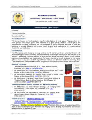
Overview of NASATransformational Tools andTechnologies Project’s 2700 FCMC/EBC Technology ChallengeJanet B. HurstMaterials and Structures Tech LeadNASA Glenn Research Center, USAAdvanced Ceramic Matrix Composites:Science and Technology of Materials, Design, Applications, Performance andIntegrationNovember 6, 2017LaFonda on the Plaza - Santa Fe, New Mexico, USA1
Acknowledgements:Transformational Tools and Technologies Project’sProject Manager – Mike Rogers ( ARC)Deputy Project Manager – Rob Scott (LaRC)Associate Project Manager – Dale Hopkins (GRC)NASA Glenn Research Center Contributors:EBCCMCDoug Kiser *Ram Bhatt*Amjad Almansour*Craig SmithSai RajSreeramesh Kalluri - OAIJoe Grady – BCJames DiCarlo*Dongming Zhu*Kang Lee*Bryan HarderNate JacobsonValerie WiesnerNarottam BansalCraig Robinson - BCModelingBrian GoodNoel NemethJerry LangSteve ArnoldRoy SullivanNASA ARC: John Lawson - modeling2
OutlineTransformational Tool and Technologies ProjectProject Overview Project Vision, Goals, ObjectivesStatus T3 Technical Challenge CMC Development EBC Development Testing Development Modeling Development Partnerships and Collaborations Future Direction Publications, Awards,Summary3
Transformational Tools & Technologies ProjectEnable fast, efficient design & analysis of advanced aviationsystems from first principles by developing physics-basedtools/methods & cross-cutting technologies, provide newMDAO & systems analysis tools, & support exploratoryresearch with the potential to result in breakthroughs.Scope Foundational cross-cutting research and technology for civil air vehicles Discipline-based research and system-level integration method development Support and enable concept development and benefits assessment acrossmultiple ARMD programs and disciplinesNear bodyseparationFlap separation4
Transformational Tools & Technologies Sub-ProjectsRevolutionary Tools and Methods Physics-based Predictive Methods for Improved Analysis and Design Improved CFD Models and Algorithms MDAO/System Analysis Tools Materials and Structures Modeling and Simulation Combustion Modeling Validation ExperimentsCritical Aeronautics Technologies High-temperature Engine Materials Multifunctional Materials and Structures Combustion Technologies Propulsion Controls Advanced Flight Controls Innovative MeasurementsEBC-Coated CMC VaneNiTiHf Shape Memory Alloytorque tube actuators for UAVflight demoT3 focuses on transformational cross-cutting foundational research5
OutlineTransformational Tool and Technologies ProjectProject Overview Project Vision, Goals, Objectives, and RelevanceStatus T3 Technical Challenge CMC Development EBC Development Testing Development Modeling Development Partnerships and Collaborations Future Direction Technical Quality: Publications, Awards, PatentsSummary6
Completion of Technical Challenge TACP02Assessment of Potential Fuel Burn and NOX Benefits of CMC Turbine Blades/Vanes on an N 2 EngineScott M. Jones and Bill Haller - Provided to Materials & Structures Division (April 2011)Incorporation of 2700F capable Ceramic Matrix Composites (CMCs) into turbines as HPTand LPT vanes and blades provides a net overall reduction of 6.0% in fuel burn and agreater than 33% reduction in NOx emissions (less cooling air, reduced weight).Success Criteria:Green: Achieve key durability metrics of 1000 cumulative hours at 30ksi max stress and 2700 F max material surface temperature.Component“Hot Life”Yellow: Achieve key durability metrics of at least 300 cumulative hoursat 20 ksi max stress and 2700 F max material surface temperature.Red: Achieve key durability metrics of less than 300 hours at 20 ksi maxstress and 2700 F max material surface temperature.Shroud (10ksi)Vane (15-25ksi)Increasing Mechanical LoadingBlade (30 ksi)7
M&S - High Temperature Engine Materials (TC #2)Transformational Tool and Technologies ProjectTechnical Challenge:Develop high temperature materials for turbineengines that enable a 6% reduction in fuel burnfor commercial aircraft, compared to currentSOA materials.Technical Areas and Approaches: Ceramic matrix composite (CMC) materialsand the required environmental barriercoating (EBC) systems are investigated anddeveloped for 2700F engine environments.PS-PVD Coating t cellModels and computational tools for design,analysis, and life prediction are developed.Benefit/Pay-off: Enables increase in engine operatingtemperature, and/or reduced cooling forturbine components.Improves fuel efficiency and helps reduceemissions.Abaqus FEMModelingAnalysis Tools SimulateFailure ProcessTesting and test methoddevelopmentTechnical Challenge - High Temperature Engine Materials8
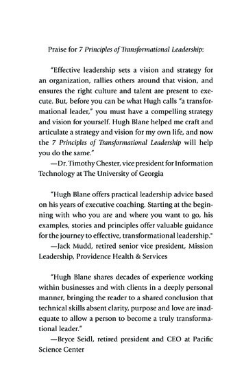
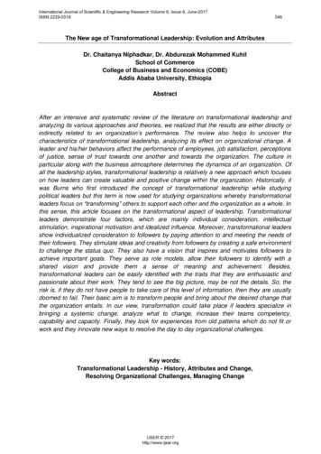
Progress Indicator Chart:M&S - High Temperature Engine Materials (TC #2)ExceedsGoal StateTargetGoal StateFails to MeetGoal StateTRL*5“Goal State” Material System Metrics:FY17 ProgressT 2700 F (CMC/EBC upper limit use temperature)σ 25 ksi (CMC matrix cracking stress)t 300 hr (cumulative “hot time” life)h 0.010 in (EBC thickness)r 0.005 mg/g-cm2-hr (EBC erosion mass loss rate)1. Demonstrated 1000 hour durability of TTT CMC/EBC at up to2700⁰F, temp and load.2. Developed unique test capabilities for CMC/ebc evaluation, steamoxidation, thermal. gradient testing, controlled environment fiber testing,2700F engine test stand with P&W.3. Developed experimental methodology and modeling capability topredict the degree of damage (crack density, extent, etc.) usingelectrical resistivity measurements.4. EBC PSPVD process optimized. EBC slurry casting methoddeveloped2700 F EBCSystemIdentified42700 F CMC/EBCIntegrated MaterialSystem Tested2700 F TurbineSubcomponentTestedL2 milestone pulled forwardto 3Q18EBC PS-PVDProcessOptimized4Material SystemDurability at 2700 FTechnical Challenge: Develop high temperature engine materials for turbine componentsenabling 6% reduction in fuel burn (requires 2700 F durability, meeting “goal state” metrics)43EBC Bond CoatCandidatesEBC MaterialsAssessed12700 F TurbineSubcomponentFabricated2,32700 F CMC 2700 F CMC 2700 F CMCCharacterizedFabricatedDemo2Hybrid SiCMatrix Process20123D CMCCharacterized2013Super-Syl-iBNFiber Process201420152016201720182019*TRL increasing integration of materials system elements & validated durability9
Outline Transformational Tool and Technologies ProjectProject Overview Project Vision, Goals, Objectives, and RelevanceStatus T3 Technical Challenge CMC Development EBC Development Testing Development Modeling Development Partnerships and Collaborations Future Direction Technical Quality: Publications, Awards, PatentsSummary10
IntroductionAircraft engine efficiency can be significantly improved with advanced materials Higher temperature materials require less cooling air Lower density materials can lead to lower weight of componentsCeramic Matrix Composites (CMCs) offer a significant improvement over metals CMCs with 2400 F capability began flying in commercial aircraft engines in 2016 This is 300 F higher temperature capability than metals, at 1/3 of the densityCFM LEAP ShroudBoeing 737Airbus A320NASA is developing a material system with 2700 F capability This technology would reduce aircraft fuel burn by approximately an additional6%, as well as lowering emissions1111
TTT 2700 F CMC IncorporatesThree Separate Technology AdvancementsTransformational Tool and Technologies ProjectSuper-Sylramic-IBNCreep-resistant SiC fiberAdvanced 3D fiber architecture“Hybrid” SiC matrixfor reduced porositySiC: Silicon CarbideCVI: Chemical Vapor InfiltrationPIP: Polymer Infiltration and PyrolysisCVI SiCPIP SiC1212
Creep- Resistant Silicon Carbide FibersTransformational Tool and Technologies ProjectThe 3 best fiber types were studied Hi-Nicalon STMSylramicTM-iBNSuper SylramicTM-iBNProduced by NASA-developedheat treatment Hi-Nicalonis the least expensiveof the three fibers and is usedcommercially by engine companies Super SylramicTM-iBN performs thebest in creepSTMFiber Creep Data1313
3D Fiber Architecture Improves Material DurabilityTransformational Tool and Technologies Project3D means fibers are oriented along X,Y,and Z axes Impact TestsYellow fibers in the diagram arethrough-thickness reinforcement2D CMCs currently beingimplemented into engines3D offers advantages over 2D Improved impact resistanceIncreased through- thicknessthermal conductivityBetter suited to the 3D stressstate of a vaneCould allow machining of coolingholes without cutting fibersThermal Conductivity1414
High Temperature Tests Show That TTT MaterialExceeds 2700 F Durability GoalsTransformational Tool and Technologies ProjectComposite Creep Data2700 F, 20 ksiSuper Sylramic-iBNMaterial has 300 hour creep life at 20 ksi/ 2700 FMeeting the Yellow Exit Criterion1515
Effect of Advanced Fiber on CMC Creep Life DeterminedTransformational Tool and Technologies ProjectHi-Nicalon-S preference due to price and availabilityHi-Nicalon-SAPPROACH Fabricate SiC / SiC Ceramic Matrix Compositeswith NASA 2700⁰F hybrid matrix composition and3D fiber architecture. Compare creep performance of CMC’s with 3different high temperature fibers (Sylramic-iBN,Super Sylramic-iBN and Hi-Nicalon-S)SIGNIFICANCE Creep life obtained with NASA Super-Sylramic-iBNfiber exceeds life obtained with commercially availablefiber by 200 hours at 15 ksi stress Hi-Nicalon STM composites tested at 15ksi/2700 F did not reach 300 hour life(TTT goal)Syramic - iBNSuper Syramic - iBN2700⁰F creep strainat 15 ksi stressCMC’s were fabricated with commercially available Hi-Nicalon-Sfiber for comparison of creep properties with TTT CMC’s usingSuper Syramic – iBN fiberPOC: Ram Bhatt16
Long-term tests demonstrate 1000-hour durability ofT3-developed CMC at 2700ºFTransformational Tool and Technologies ProjectCreep RuptureData10 ksi stress level is representative ofa lightly-loaded structural component(turbine shroud) in current enginesFY17 Accomplishments:Yellow Exit Criterion: Achieve key durabilitymetrics of at least 300 cumulative hours at 20 ksimax stress and 2700 F max material surfacetemperature. Static tensile testing demonstrated onset of damage (matrix cracking) at 18-29 ksi applied mechanicalstress at 2700ºF Isothermal Creep Rupture testing of CMC demonstrated 1000 hrs durability under 10 ksi, 800 hoursunder 17.5 ksi applied mechanical stress, and at 2700ºF; other tests at 17.5 and 20 ksi are still underway. Isothermal Sustained Peak Low Cycle Fatigue (SPLCF) testing of CMC failed at 780 hours at 17.5 ksimaximum applied mechanical; Another test at 17.5 ksi has accumulated 100 hours and is still underway. High heat flux SPLCF testing, with laser heating, survived nearly 500 hours. Demonstrated several coating methods with a variety of NASA patented coating compositions. Methodsinclude PSPVD EBC coating fabrication, Electron Beam-Physical Vapor Deposition and Directed VaporDeposition (DVD) and slurry casting EBC.17
High Temperature Engine Materials: Ceramic Matrix CompositesDevelopmentTransformational Tool and Technologies ProjectNDE Technique Extended to 2400⁰F ApplicationsPROBLEMTracking damage progression in CMCs can not be done at high temperaturesOBJECTIVENon-Destructive Evaluation of CMC’s is neededat high temperatures to detect matrix cracksthat lead to failureAPPROACH Conduct long-term tests at 1500⁰F and 2400⁰Fwhile monitoring electrical resistance . Relate changes in electrical resistance to CMCdamage and microstructural changes.CMC electrical resistance wasmonitored while matrix cracksformed during long term testsSUMMARY & RESULTS 6,881 hours of long-term tests were conducted at high temperatures Changes in electrical resistance at 1500⁰F were directly related to thedensity of matrix cracks in the CMC At 2400⁰F, electrical resistance measurements were less sensitive todamage by an order of magnitudeSIGNIFICANCEThe relationship between CMC electrical resistance and damage athigh temperatures was determined, establishing the basis of a newexperimental method for characterizing CMC durability under aircraftengine operating conditions.In-situ resistance of stressed-oxidationsamples tested at 815 CPOC: Craig Smith, Ph.D.18
Modeling CMC MatrixMatrix Development ContinuesEngineered MatrixDurable filler matrix for CVI SiC/SiC preforms withproperties engineered to increase crack resistance and selfhealing capabilities.FEA model of a representative 2700F CMCusing known constituent properties andarchitectureSai Raj Partnered withARFLMinicomposites Evaluated –additional vendorStatus: Validation ofproperty predictionresults has beenachieved.Model calculationswere within 10% oflaboratorymeasurementsand literature data.Jerry LangModel electrical resistance measurementsindicating CMC damage developmentModel of unit cell withcracks in 90 tow andmelt-infiltrated SiCmatrix.Amjad Almansour/Doug Kiser – with University ofConnecticut, and also Rolls Royce; AFRL, UCSBCracking within the 0 or 90 tows - insignificant effectCracking of (MI) SiC matrix –signicant effect on19electrical resistivity.
OutlineProject Overview Project Vision, Goals, Objectives, and RelevanceStatus T3 Technical Challenge CMC Development EBC Development Testing Development Modeling Development Partnerships and Collaborations Future Direction Technical Quality: Publications, Awards, PatentsSummary20
Degradation of CMCs in Turbine Engines Incorporation of CMCs into turbine hotsection has substantial benefits 1990: Observation that SiC undergoes rapidrecession in water vapor (Opila/NASA) 1990s: Develop dense oxide coatings toprotect against water vapor attack(Lee/NASA) CMC2000s: Development of coatings to minimizewater vapor effects at 2400 F: Gov’t labs(US, Japan, Germany); turbine companiesNASA research is focused on the next generation of CMC/EBC systems capableof operating at 2700 F with reduced or no cooling21
Candidate Coating System Requirements NASA has focused on developing next generation environmental andmechanically durable material systems for 2700 F and beyond. Environmental Barrier Coating (EBC) System–––––EBCMay consist of bond coat and top coatWell matched to CMCStable above use temperatureLow reactivity with H2OLimited cracking/pathways for oxidants EBC is essential for CMC operation– Uncoated CMC suffers rapid recession– 300 hour minimum cumulative “hot time” lifeBond CoatCMCEBCBond CoatCMC22
Environmental Barrier Coating Failure Modes23H2OSiO2Bond Coat Steam oxidationCMC Sand/Volcanic Ash Ingestion CMAS: CalciumMagnesium-Alumino-SilicateCMCH2OSi(OH)4 (gas)EBCEBCCMCCycleunderDTEBCCMC Recession bywater vapor Thermal fatigue Thermo-mechanicalfatigueCMC ErosionFODEBC Foreign Object DamageCMCSynergies between failure modes lead to the ultimate EBC failureK. N. Lee, “Environmental Barrier Coatings for CMC’s”; in Ceramic Matrix Composites, Wiley, New York (2015)23
Thermochemistry and Modeling Stability of prospective EBC materials withwater vapor measured– Experiments and model based approachH2OSi(OH)4 (gas)EBC Evaluated prospective EBC materialsystems for turbine engine environments Determine reaction chemistry and usemodels to predict recession ratesProspective Environmental Barrier Coatingsreduce recession rates of CMCs by 70%,enabling lifetimes needed for use in turbineenginesCMCUncoated CMCEBC70% ReductionRecession Rates at 2700 F24
High Temperature Engine MaterialsEnvironmental Barrier Coatings DevelopmentOBJECTIVEEvaluate and Model Environmental Barrier Coating (EBC) – Thermally Grown Oxide (TGO)interaction and impact of EBC chemistry/composition on TGO growth rate and TGOcrystallization behavior.Undoped Yb2Si2O7 100 hrs 90%H2 OEBCAPPROACH Examination and testing of multiple coating processing methods for limiting SiO2(TGO) growth at the substrate as a function of microstructure and composition anddownselect for minimization of TGO growth in cyclic exposure to 90% H2O/O2 at2600F for 100 hours.SIGNIFICANCEControl and minimization of the TGO growth at the CMCsubstrate is critical to CMC/EBC durability and life.Oxidation in water vapor is an order of magnitude fasterthan in air and must be addressed for long term CMC/EBCdurability.SiO2 layer (TGO)SiC/SiC80 mmEBCSiC/SiCACCOMPLISHMENTSDoped Mullite 100 hrs 90% H2O Multiple compositions have been deposited via PS-PVDand slurry processing methods and tested in cyclicsteam oxidation at 2600 F in 90% H2O/O2 for 100 hours or more. All EBCs maintained adherence after 100 hours, and new coatingchemistries deposited via slurry methods show promise for furtherreduction of the oxidation rate beyond 300 hours.Additional samples will be processed via both methods and testedto evaluate the composition and microstructural impact onoxidation durability.POC: Bryan Harder, Kang Lee (GRC)Suppression ofOxidation Rateat 2600 F25
Advanced Coating Processing New processing methods allow foradvanced architectures and compositionsPS-PVD Rig Plasma Spray- Physical Vapor Deposition– Unique facility at Glenn Research Center and oneof a handful worldwidePS-PVD Deposition of Coatings Some non-line of sight deposition canprovide coverage on complex shapesAdvanced Coating Processing Methods haveprovided new capabilities which areadvantageous for cost and performance26
OutlineProject Overview Project Vision, Goals, Objectives, and RelevanceStatus T3 Technical Challenge CMC Development EBC Development Testing Development Modeling Development Partnerships and Collaborations Future Direction Technical Quality: Publications, Awards, PatentsSummary27
New Facilities Constructed for 2700F CMC/EBCFacilityTTT Funding CE-5full Horizontal Cyclic Steam Rigfull Fullpartial Drop CalorimeterPSPVDliquidLaser III Laser IVpartial Slurry cast processingNatural Gas Burner Rigpartialpartial high temperature furnaceSteam Tensile Fatiguepartialpartial Small Loading Fixturefull Fiber Dia. Rigfull 5-Fiber Creep Rigfull Minicomposite RT/HT FF testMinicomposite HT creep in airGlovebox #2Fiber testing vacuum/inertfullfullfullpartial Erosion/CMAS rigFlexural Fatigue Steam RigIn-Situ Flex LoadingpartialpartialpartialpartialPurposeNew capability for high TRL level "in-house" combustion testing.Investments include design & build of test fixtures, testingNew capability with increased temperature range ( 2600 F), multiplesample configurations, higher thruputnew capability for thermodynamic studies.Existing capability has been highly invested in, added non LOS andfeed capabilitiesExisting Rig: upgrades to safety systems, new control systems,instrumentationNew capability (multi-axis mechanical fatigue, additional thermalgradient):New capability for processing EBCsNew capability for high heat flux, high velocity, volatility in H20,complex geometriesNew melt infiltration furnace procuredUpgrades to steam rig with durable a) commercially coated and b)EBC coated (developed at GRC) heating elements – 2600FFor tensile and compressive testing of CMCs and minicomposites inFESEM. Very few in the U.S.New capability. Accurate fiber diameters prior to creep/stressoxidation testing, should reduce data scatter.New capability. For conducting five fiber creep/stress oxidationtests simultaneously at temperatures up to 2700F.New capabilityNew capabilityhigh temperature fiber testing in inert.Existing rig fixed and modified to test multiple fibers in creep invacuum/inertEnhanced to offer CMAS erosion feed to existing erosion capabilityNew capability for flexural SPLCF testing in steamNew capability for optical/ electron microscopy of under flexuralloading condition.28
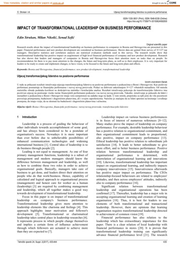
Thermomechanical Testing of NASA CMC/EBC System First integration and testing of NASAdeveloped CMC with the NASAdeveloped EBC system Sustained peak low cycle fatigue(SPLCF) test with laser gradient heatingfor thermomechanical validation Milestone set at 300 hours with a 2700 FCMC temperature and 10ksi loadCycleunder DTEBCMechanicalLoadingCMCLaserHeatingCMC withEBCEBC coated CMC under stress heated bya high heat flux laserEBC Surface Temperature: 2950 FCMC Temperature: 2700 FLoad: 10ksiTotal Life: 487 hoursAfter 487 hour testing29
TRL 5 Rig Test Planned for FY18CMC sub-element will be used to evaluate material capabilitiesin a simulated turbine environment Airfoil-shaped test article, 3x3 inchesUTRC HPTC test rig Gas temperature up to 3600 F Mach No. 0.2 M 0.8 in test section 1.5 lb/s airflow at 220 psia Internal specimen cooling allows for a tunablethrough-thickness temperature gradient Thermocouples, pyrometers and IR cameramonitor material temperatures NASA / P&W / UTRC collaborationairfoilsubelementssubelement mounting fixture3030
OutlineProject Overview Project Vision, Goals, Objectives, and RelevanceStatus T3 Technical Challenge CMC Development EBC Development Testing Development Modeling Development Partnerships and Collaborations Future Direction Technical Quality: Publications, Awards, PatentsSummary31
Vision 2040 for Integrated, Multiscale Materials andStructures Modeling/Simulation NRAKey Element Domains2040 Vision StateA cyber-physical-socialecosystem that impacts thesupply chain to acceleratemodel-based concurrentdesign, development, anddeployment of materialsand systems throughoutthe product lifecycle foraffordable, producibleaerospace applicationsNeeded to overcome various gaps and challenges to achieve the fullyintegrated 2040 Vision end statePhase IIPhase I32
ModelingNeed for a wide range of approaches (different scales) for CMC and CMC/EBCsystem modeling to provide understanding of behavior / performance;-enabling life prediction and understanding of effects of coating and constituentsGoal: Model behavior of GRC Hybrid 3D SiC/SiC/ GRC EBC system Multiscale/ Multiphysics Modeling-Large portfolio of internal codes / software, many of which couple with commercial codes(e.g., Abaqus, Ansys, Comsol, etc.)-Computationally-efficient methods / tools-Nonlinear deformation and damage modeling capabilitiesHave modeled CMC laminate systems, SiC fibers, and CVI SiC/SiC mini-composites Conducting test plan to identify environmental effects:Need to:- Robust models of woven 3D composites extended to in-house MAC/GMC code- Air, inert, steam, CMAS (calcium magnesium aluminosilicate) and creep / fatigueinteraction with environment- Predictive capability33
OutlineProject Overview Project Vision, Goals, Objectives, and RelevanceStatus T3 Technical Challenge CMC Development EBC Development Testing Development Modeling Development Partnerships and Collaborations Future Direction Technical Quality: Publications, Awards, PatentsSummary34
Partnerships and CollaborationsIndustry Stakeholders:GERolls RoycePratt & WhitneyOerlikon MetcoDirected Vapor (DVTI)Southwest ResearchBoeingBlue QuartzGovernment:AFRLArmyNAVAIRDOE- ORNLFAASlurryFibertowsAcademia:UConnU of MICal TechU of California- Santa BarbaraU of VirginiaPurdue UClemson UPennsylvania State UAkron ULeveraging external collaborations toaugment and complement in-houseresearch35
OutlineProject Overview Project Vision, Goals, Objectives, and RelevanceStatus T3 Technical Challenge CMC Development EBC Development Testing Development Modeling Development Partnerships and Collaborations Future Direction Publications, PatentsSummary36
Next StepsDevelop & validate models to predict environmental effects onCMC / EBC durabilityTTT Create/utilize life prediction models forpredictive and prescriptive engineering (Vision 2040) thermal / mechanical cycling incorporation of steam sand/volcanic ash (CMAS) degradationAddress for durable CMC turbine components optimal cooling schemes for turbine blades & vanes blade / disk attachment design, analysis & testing development of in-house combustion test capabilitiesAccelerate engine implementation demonstrate improved fabricability/feasibility of CMCadditive manufacturing3737
CE-5 Test Development Coupon & Vane holder Designs– 1” cooled Button Sample Holder Mech design & thermals complete Fab underway– Vane pack near completion Solving thermal issues with platforms 2”x2” vanes accommodated Configuration Flexible– Either holder in downstream as piggyback to injector testing– Coupon upstream Vane downstreamas stand alone customer.– Reaches 30 atm (vs 6-8 atm for HPBR) Take-up spoolAir/H2OTC ProbeCE5 combustion rig test fixture designcompleted–––Text fixtures for coupons and airfoil subcomponentsClosest to engine environments among ourtest facilitiesEBC-coated CMC durability with and withoutcooling holes to support TTT and AATTPyro38
OutlineProject Overview Project Vision, Goals, Objectives, and RelevanceStatus T3 Technical Challenge CMC Development EBC Development Testing Development Modeling Development Partnerships and Collaborations Future Direction Patents, PublicationsSummary39
Publications SummaryJournal ConferenceNASABookarticles presentation reports chaptersFY14Structures and Materials144782FY15Structures and Materials156992FY16Structures and Materials2646172FY17Structures and Materials138410440
FY16-17 PatentsHigh Temperature MaterialsIssued Patents:1.NASA LEW-18769-1 Utility Patent, “Acoustic Liners for Turbine Engines” James Kiser,2.NASA LEW-18769-2 Utility Patent, “Improved Acoustic Liners for Turbine Engines” JamesKiser, Joseph GradyJoseph GradyPatent applications:1.NASA LEW-18949-2, Utility Patent ,“Advanced High Temperature and Fatigue ResistantEnvironmental Barrier Coating Bond Coat Systems for SiC/SiC Ceramic Matrix Composites”,Zhu, Hurst2.NASA LEW-18964-2 Patent App, “Engineered Matrix Self-Healing Composites”, Sai Raj3.4.5.NASA LEW 18970-2 Provisional Patent, “Method of Exfoliating BN”, Ching-cheh ,Hung, Janet HurstNASA LEW 18970-3 Provisional Patent, “Method of Exfoliating BN”, Ching-cheh Hung, Janet HurstNASA LEW-19435-1 Provisional Patent, Patent Application, “Advanced High TemperatureEnvironment Barrier Coatings for SiC/SiC Ceramic Matrix Composites”, Dongming Zhu6.NASA LEW-19435-2 Provisional Patent, Patent Application, “Advanced High TemperatureEnvironment Barrier Coatings for SiC/SiC Ceramic Matrix Composites”, Dongming Zhu7.NASA LEW 19456-1, Provisional Patent ” Ultra High Temperature Ceramic Coatings andCeramic Matrix Composite Systems”: Dongming Zhu and Janet Hurst8.NASA LEW-19283-1 Patent App “Ultra High Temperature Ceramic Coatings and CeramicMatrix Composite Systems”, Dongming Zhu, Janet HurstNASA LEW 19691-1 Patent App,“Rapid Processing Method for Tailoring Properties of Silicon CarbideTows”, Maricela Lizcano, Janet Hurst9.41
OutlineProject Overview Project Vision, Goals, Objectives, and RelevanceStatus T3 Technical Challenge CMC Development EBC Development Testing Development Modeling Development Partnerships and Collaborations Future Direction Publications, PatentsSummary42
Accomplishments & Challengesfor Engine Applications of CMCs and EBCsTTT Accomplishments (FY13-FY17) Determined effect of advanced SiC fiber on CMC durability Achieved the TTT goal of demonstrating 300 hour CMC life at 20ksi /2700 F- yellow success criterion Measured prospective EBC material stability in turbine environments Established new processing methods for advanced EBC architectures Demonstrated 1000 hour durability of TTT CMC/EBC at 2700 FFuture challenges (FY18 and beyond) P&W engine rig testing Identifying operating limits (temperature/time/stress) of currentCMC/EBC Physics-based models of environmental effects on CMC/EBC durabilityGoal – Understanding/predicting role of engine environment (steam,CMAS) in CMC/EBC life4343
44
NASA ARC: John Lawson - modeling . Discipline-based research and system-level integration method development . r 0.005 mg/g-cm2-hr (EBC erosion mass loss rate) 1 4 2,3 L2 milestone pulled forward to 3Q18. 10 Outline Project Overview Project Vision, Goals, Objectives, and Relevance